Matrix ClimbMill C50-F User manual

2019C50-F CLIMBMILL
SERVICE MANUAL

CHAPTER 1: SERIAL NUMBER LOCATION ........................................................... 1
CHAPTER 2: IMPORTANT SAFETY INSTRUCTIONS
2.1 Read and Save These Instructions............................................................................. 2
2.2 Electrical Requirements ............................................................................................. 4
2.3 Locating the Unit ......................................................................................................... 5
2.4 Stabilizing the Climbmill .............................................................................................. 6
CHAPTER 3: PREVENTIVE MAINTENANCE
3.1 Care and Maintenance Instructions ........................................................................... 7
CHAPTER 4: TROUBLESHOOTING
4.1 Electrical Diagram ...................................................................................................... 8
4.2 LCB LED Indicators ................................................................................................... 16
4.3 Error Code List............................................................................................................ 18
CHAPTER 5: PART REPLACEMENT GUIDE
5.1 Service Cover Replacement ...................................................................................... 20
5.2 Side Cover Replacement ........................................................................................... 21
5.3 Console Replacement................................................................................................. 22
5.4 Front Shroud Replacement......................................................................................... 23
5.5 Lower Control Board (LCB) Replacement .................................................................. 25
5.6 Handlebar Set Replacement....................................................................................... 26
5.7 Emergency Stop Set Replacement............................................................................. 27
5.8 Handgrip Service......................................................................................................... 29
5.9 Stair Replacement....................................................................................................... 30
5.10 Drive Belt Replacement .............................................................................................. 32
5.11 Drive Set Replacement ............................................................................................... 33
5.12 Chain Replacement..................................................................................................... 35
5.13 Brake Replacement..................................................................................................... 37
5.14 Coded Disc Replacement ........................................................................................... 38
5.15 Speed Sensor Replacement ....................................................................................... 49
5.16 Control Zone Replacement ........................................................................................ 41
5.17 Proximity Sensor Replacement................................................................................... 42
5.18 IR Sensor Replacement.............................................................................................. 43
5.19 Testing the Climbmill ................................................................................................... 44
CHAPTER 5: SOFTWARE UPGRADE GUIDE
6.1 XIR/XER UCB Software Procedure from USB ........................................................... 45
6.2 XIR/XER UCB Software Procedure from Website...................................................... 46
6.3 XR UCB Software Procedure from USB..................................................................... 47
CHAPTER 7: DOCUMENT UPDATE HISTORY
7.1 Document Update History........................................................................................... 48
TABLE OF CONTENTS

1
1.1 SERIAL NUMBER LOCATION
CHAPTER 1: SERIAL NUMBER LOCATION
SERIAL NUMBER LOCATION

2
2.1 READ AND SAVE THESE INSTRUCTIONS
CHAPTER 2: IMPORTANT SAFETY INSTRUCTIONS
•If you experience any kind of pain, including but not limited to chest
pains, nausea, dizziness, or shortness of breath, stop exercising
immediately and consult your physician before continuing.
•When exercising, always maintain a comfortable pace.
•Do not wear clothes that might catch on any part of the equipment.
•Always wear athletic shoes while using this equipment.
•Do not jump on the equipment.
•At no time should more than one person be
on equipment while in operation.
•This equipment should not be used by persons weighing more
than specified on this card. Failure to comply will void the warranty.
•This equipment should not be used by persons weighing less
than specified on this card. Failure to comply may cause injury.
•Disconnect all power before servicing or moving the equipment. To
clean, wipe surfaces down with soap and slightly damp cloth only;
never use solvents. (See MAINTENANCE in OWNER’S MANUAL)
•The equipment should never be left unattended
when plugged in. Unplug from outlet when not in
use, and before putting on or taking off parts.
•Do not operate under blanket or pillow. Excessive heating can
occur and cause fire, electric shock, or injury to persons.
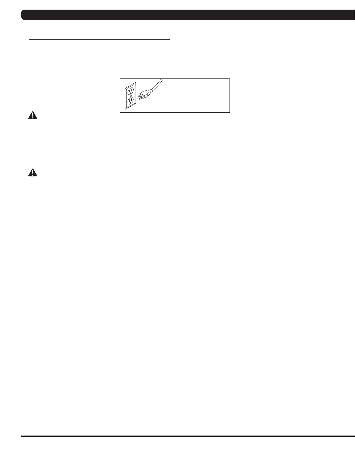
•Connect this exercise product to a properly grounded outlet only.
•At NO time should children under the age of 14
or pets be within 10 feet of the machine.
•Keep children under the age of 14 away from this
exercise equipment. Teenagers must be supervised
at all times while using this equipment.
•This equipment is not intended for use by persons with
reduced physical, sensory or mental capabilities, or lack
of experience and knowledge, unless they have been
given supervision or instruction concerning use of the
equipment by a person responsible for their safety.
•Use the equipment only for its intended use
as described in the owner’s manual.
•Do not use other attachments that are not recommended
by the manufacturer. Attachments may cause injury.
•Never operate the equipment if it has a damaged cord or
plug, if it is not working properly, if it has been dropped or
damaged, or immersed in water. Contact Customer Tech
Support at the number on the back cover to schedule service.
•Keep power cord away from heated surfaces. Do not carry
this unit by its supply cord or use the cord as a handle.
•Never operate the equipment with the air opening blocked.
Keep the air opening clean, free of lint, hair, and the like.
•To prevent electrical shock, never drop or
insert any object into any opening.
•Do not operate where aerosol (spray) products are
being used or when oxygen is being administered.
•To disconnect, turn all controls to the off
position, then remove plug from outlet.
•Do not use equipment in any location that is not
temperature controlled, such as but not limited to
garages, porches, pool rooms, bathrooms, car ports or
outdoors. Failure to comply may void the warranty.
•This equipment is intended for in-home use only. Do not
use this equipment in any commercial, rental, school or
institutional setting. Failure to comply will void the warranty.
•Do not remove the console covers unless instructed
by Customer Tech Support. Service should only be
done by an authorized service technician.

3
2.1 READ AND SAVE THESE INSTRUCTIONS - CONTINUED
CHAPTER 2: IMPORTANT SAFETY INSTRUCTIONS
PROPER USAGE
MOUNTING THE CLIMBMILL
1. There are two EMERGENCY STOP BUTTONS on the
ClimbMill. One emergency stop button is located at the top of
the handlebars and the second is located on the lower right
side handlebar. The EMERGENCY STOP BUTTONS will
bring the step surfaces to a complete stop when pressed.
2. The CONTROL ZONE will bring the step surfaces to
a complete stop upon detecting an object. The AUTO-
STOP SENSOR will bring the step surfaces to a complete
stop upon detecting an object under the bottom step.
3. Stand directly behind the ClimbMill on the CONTROL
ZONE. Grasp the handlebars and step onto the ClimbMill
until you are within comfortable reach of the console, top
emergency stop lever, and in-reach handlebar controls.
4. To determine proper workout position, stand on the
steps within comfortable reach of the console. Maintain a
constant distance from the console and in-reach handlebar
controls. Keep your knees slightly bent at all times.
5. Dismounting the ClimbMill - After the steps have
come to a complete stop and while grasping the
handlebars, step down onto the CONTROL ZONE.
POWER
The power cord must be plugged into the power socket, which is
located in the front of the equipment on the front of the machine.
The power switch is located next to the power socket. Make
sure it is in the on position. Unplug cord when not in use.
WARNING!
Never operate product if it has a damaged cord or plug, if it
is not working properly, if it has been damaged, or immersed
in water. Please reference contact information on the back
cover of the INFORMATION CARD for assistance.
Emergency stop
Emergency stop
AUTO-STOP SENSOR
CONTROL ZONE

4
CHAPTER 2: IMPORTANT SAFETY INFORMATION
2.2 ELECTRICAL REQUIREMENTS
GROUNDED POWER CORD
3-POLE GROUNDED OUTLET
GROUNDING INSTRUCTIONS
This product must be grounded. If the equipment should malfunction or breakdown, grounding provides a path of least resistance for electrical
current to reduce the risk of electrical shock. This product is equipped with a cord having an equipment-grounding conductor and a grounding
plug. The plug must be plugged into an appropriate outlet that is properly installed and grounded in accordance with local codes and ordinances.
DANGER
Improper connection of the equipment-grounding conductor can result in a risk of electric shock. Check with a qualified
electrician or serviceman if you are in doubt as to whether the product is properly grounded. Do not modify the plug
provided with the product. If it will not fit the outlet, have a proper outlet installed by a qualified electrician.
This product is for use on a nominal 110-120 Volt circuit and has a grounding plug that looks like the plug in the illustration. Make sure
that the product is connected to an outlet having the same configuration as the plug. No adapter should be used with this product.
WARNING
Connect this exercise product to a properly grounded outlet only.
Never operate product with a damaged cord or plug even if it is working properly. Never operate any product if it appears
damaged, or has been immersed in water. Contact Customer Tech Support for replacement or repair.
It is essential that this equipment is used only indoors, in a climate controlled room. If the equipment has been exposed to colder temperatures or
high moisture climates, it is strongly recommended that the equipment is warmed up to room temperature before first time use. Failure to do so
may cause premature electronic failure.

5
2.3 LOCATING THE UNIT
CHAPTER 2: IMPORTANT SAFETY INSTRUCTIONS
LOCATION OF THE UNIT
Place the ClimbMill on a level surface. For ease of access,
there should be an accessible space preferentially on both
sides and the rear of the ClimbMill that is at least 0.6 meters
(24 inches). Do not place the ClimbMill in any area that will
block any vent or air openings. The ClimbMill should not be
located in a garage, covered patio, near water or outdoors.
HEIGHT AND WEIGHT REQUIREMENTS
The equipment adds 20” – 25” (50 – 64.5 cm) to a user’s height.
For example, a 6’1” (185 cm) tall user will be 7’9” – 8’2” (236 – 249
cm) off the floor. The C50 requires a minimum user weight of 99 lbs
(45 kgs) and has a maximum user capacity of 300 lbs (136 kgs).
FOOTPRINT: 135 x 72 cm / 53” x 28”
HEIGHT: 190 cm / 75”
WEIGHT: 138.5 kg / 293 lbs.
MOVING THE UNIT
The ClimbMill has a pair of transport wheels built into the
front of the frame. To move, first remove the power supply
and firmly grasp the console mast, carefully tilt (1) and roll (2).
Note: be sure to grab the steel bar and not the console.
FREE AREA
0.6 M (2 FT)

6
CHAPTER 2: IMPORTANT SAFETY INSTRUCTIONS
2.4 STABILIZING THE CLIMB MILL
LEVELING THE EQUIPMENT
Locate a level, stable surface to position the equipment. The equipment has levelers located below the Control Zone
step. Raise or lower one or both of the adjustable levelers using a 6mm allen wrench through the access hole.
A carpenter’s level is recommended.
NOTE: There are only two levelers on the equipment.
LEVELER

7
3.1 CARE AND MAINTENANCE INSTRUCTION
CHAPTER 3: PREVENTIVE MAINTENANCE
MAINTENANCE SCHEDULE
ACTION FREQUENCY
Clean and inspect the ClimbMill:
• Turn off the machine with the ON/OFF switch, then unplug the power cord at the wall outlet.
• Clean entire machine using water and a mild soap applied to a soft cloth. Never use solvents, as they can
cause damage to the ClimbMill. Never spray cleaner directly onto the machine or console.
• Inspect the power cord. If the power cord is damaged, please reference contact information on the back
cover of the INFORMATION CARD for assistance.
• Make sure the power cord is not underneath the machine or in any other area where it can become pinched
or cut during storage or use.
• If any labels are damaged or illegible, please reference contact information on the INFORMATION CARD for
replacement.
BEFORE EACH USE
Clean underneath the machine:
• Turn off the machine with the ON/OFF switch, then
• unplug the power cord at the wall outlet.
• Remove the debris tray from under the machine by sliding it out from the right side and wipe or vacuum any
grease, dust particles or other objects that may have accumulated on it. Return the debris tray to its previous
position.
• Wipe or vacuum any dust particles or other objects that may have accumulated around the machine.
WEEKLY
Unplug the ClimbMill and clean the AUTO STOP SENSORS (located under the bottom step). WEEKLY
IMPORTANT!
• Turn off the machine with the ON/OFF switch, then unplug the power cord at the wall outlet. Wait 60
seconds.
• Inspect all assembly bolts of the machine for proper tightness. Reference assembly steps for proper tension
of each bolt.
• Remove the front access cover. Wait until ALL LED lights turn off.
• Clean the motor and lower board area to eliminate any lint or dust particles that may have accumulated.
Failure to do so may result in premature failure of key electrical components.
• Check step motion by rotating the steps backwards to ensure free movement.
• Check stability to ensure the ClimbMill does not rock or wobble. Adjust levelers as necessary.
MONTHLY
AUTO STOP SENSORS

8
4.1 ELECTRICAL DIAGRAMS
CHAPTER 4: TROUBLESHOOTING
SYSTEM BLOCK

9
4.1 ELECTRICAL DIAGRAMS - CONTINUED
CHAPTER 4: TROUBLESHOOTING
AG12- SAFE SWITCH SET (HANDLEBAR)
AC15 - SAFE SWITCH SET (CONSOLE MAST)

10
P01 - DIGITAL COMMUNICATION WIRE
P17- SPEED FEEDBACK EXTENSION WIRE
4.1 ELECTRICAL DIAGRAMS - CONTINUED
CHAPTER 4: TROUBLESHOOTING
AB
P16 - ECB LOAD WIRE

11
4.1 ELECTRICAL DIAGRAMS - CONTINUED
CHAPTER 4: TROUBLESHOOTING
P18 - SPEED FEEDBACK EXTENSION WIRE (PULLEY)
P19 - POWER EXTENSION WIRE

12
P27 - PULSE CONNECT WIRE
4.1 ELECTRICAL DIAGRAMS - CONTINUED
CHAPTER 4: TROUBLESHOOTING
P21 - SENSOR EXTENSION WIRE

13
P69 - PROXIMITY SENSOR CONNECT WIRE
4.1 ELECTRICAL DIAGRAMS - CONTINUED
CHAPTER 4: TROUBLESHOOTING
P28 - LIMIT SWITCH WIRE; A

14
4.1 ELECTRICAL DIAGRAMS - CONTINUED
CHAPTER 4: TROUBLESHOOTING
G39 - H/P SENSOR WIRE (L)
G40 - H/P SENSOR WIRE (R)

15
4.1 ELECTRICAL DIAGRAMS - CONTINUED
CHAPTER 4: TROUBLESHOOTING
P51 - SENSOR WIRE SET
P68 - SAFE SWITCH EXTENSION WIRE

16
4.2 LCB LED INDICATORS
CHAPTER 4: TROUBLESHOOTING
Console
RPM
Proximity Sensor
Pressure Sensor
(Control zone)
Brake
ECB 1/
ECB 2
E_STOP
LED18
LED19
LED20
LED15
LED13
Frame IR
(Receiver)
Frame IR
(Transmitter)
LED12
v
v
LED8
LED10
V
V
LED5
LED7
LED 21
RPM1
LED1/
LED2/
LED3/
LED4

17
4.2 LCB LED INDICATORS - CONTINUED
CHAPTER 4: TROUBLESHOOTING
LED DESCRIPTION DESCRIPTION STATUS
LED1 LCB software working status Flashing - Working
OFF - Default
LED2 LCB Error status Light - LCB with error
Off - LCB without error
LED3 Safety Key action status Light - Active
Off - No active
LED4 UCB and LCB communication status Flashing - Active
Off - Abnormal
---------------------------------------------------------------------------------Firmware definition-----------------------------------------------------------------------------------
--------------------------------------------------------------------------------Hardware definition-----------------------------------------------------------------------------------
LED DESCRIPTION DESCRIPTION STATUS
LED5 DC 24V lamp Indicates if the voltage supply is present
Light - Working
Off - Not working
LED7 DC 3.3V lamp Indicates if the voltage supply is present
Light - Working
Off - Not working
LED8 Electro-magnet device 2 PWM lamp Indicates if the ECB PWM signal supply is present
Light - Working
Off - Not working
LED10 Electro-magnet device 1 PWM lamp Indicates if the ECB PWM signal supply is present
Light - Working
Off - Not working
LED12 DC brake release lamp (manual switch) Light - The brake is on release position
Off - The brake is on lock position
LED13 DC 12V lamp Indicates if the voltage supply is present
Light - Working
Off - Not working
LED15 Frame IR transmitter power lamp Indicates if the Frame IR transmitter power supply is present
Light - Working
Off - Not working
LED18 Proximity sensor signal lamp Flashing - Signal detected from proximity sensor
LED19 RPM signal lamp Flashing - Detecting RPM from speed sensor
LED20 E-STOP signal lamp
(only E-STOP of console mast/arm rest set)
Light - E-Stop active
Off - E-Stop not active
LED21 RPM1 signal lamp Flashing - Detecting RPM from the second speed sensor
Console
RPM
Proximity Sensor
Pressure Sensor
(Control zone)
Brake
ECB 1/
ECB 2
E_STOP
LED18
LED19
LED20
LED15
LED13
Frame IR
(Receiver)
Frame IR
(Transmitter)
LED12
v
v
LED8
LED10
V
V
LED5
LED7
LED 21
RPM1
LED1/
LED2/
LED3/
LED4

18
CHAPTER 4: TROUBLESHOOTING
4.3 ERROR CODE LIST
02XX: LCB Errors
CODE CLASS DESCRIPTION MACHINE SOLUTION
02AB CMachine type
error. CChange the machine type on the console to match the correct frame.
02A0 CEncoder error C
a. Check the connection of the speed sensor cable from the LCB to the speed sensor.
b. Check to see if LED19 on the LCB is on when the brake is turned to the left release
position.
c. If it is off, move the stairs about 3 stairs and check to see if LED19 is flashing.
- If not, replace the first speed sensor (near the brake).
- If yes, adjust the first speed sensor position and clean the speed sensor of any
debris then re-test.
02B2 CSafe key action
response C
a. Check the connection of the safety key (emergency stop) switch. If the switch is
always open or shorted out, replace the switch.
b. If the emergency stop does not resolve the issue, replace the UCB.
02B4 CResistance
Type Error. C
a. Make sure machine type is set for the correct frame in console.
- If yes, replace LCB.
- If no, change to correct type and reboot the power.
02BF CDC brake Over
Current C
a. Check the power extend wire connection between the brake and LCB for any damage.
b. Check to see if the stairs will move when you are in the stop position. If yes, replace
the brake.
02C0 CDC brake in
manual mode. C
a. Check if the DC brake is in the right, lock position. Turn the brake (move to the right) if
in release position.
b. Replace the brake.
02C1 CSpeed tracking
error C
a. Adjust the speed sensor position and clean the speed sensor of any debris.
b. Check the ECB extension cable connection at the LCB (pins 1 & 3 for ECB1), there
should be between 9.5 ~ 10.9 ohms, check which ECB is outside the range and replace
it.
01XX: Motor Errors
CODE CLASS DESCRIPTION MACHINE SOLUTION
01AC C
Electro magnet
(ECB) over cur-
rent.
C
a. On standby mode, measure the resistance on ECB1. Please check the ECB extension
cable connection
at the LCB (pins 1 & 3 for ECB1, there should be between 10.13 ~ 10.27 ohms.
- If the ECB resistance is out of the range, replace the ECB.
- If the ECB resistance is within the range, replace the LCB.
b. Check the gap of ECB1. There should be a gap of .5mm between the ECB and the
flywheel.
01AF C
Electro magnet
(ECB) discon-
nected.
C
a. Check the connection of the ECB extension cable from the LCB to the ECB.
b. On the workout, check to see if LED10 on the LCB have a brief light.
- If LED10 do not have a brief light, replace the LCB.
- If LED10 do have a brief light, check the ECB extension cable connection at the LCB
(pins 1 & 3
for ECB1), there should be between 10.13 ~ 10.27 ohms.
- If the ECB resistance is out of the range, replace the ECB.
- If the ECB resistance is within the range, replace the LCB.
Table of contents
Other Matrix Fitness Equipment manuals

Matrix
Matrix G3S76 Instruction Manual

Matrix
Matrix 1x User manual

Matrix
Matrix G7-S75 User manual

Matrix
Matrix MAGNUM SERIES User manual

Matrix
Matrix MAGNUM SERIES User manual

Matrix
Matrix CONNEXUS Series User manual

Matrix
Matrix ULTRA Series User manual

Matrix
Matrix G7-S12 User manual

Matrix
Matrix VS-S52 User manual

Matrix
Matrix CXC User manual

Matrix
Matrix MX-S71 User manual

Matrix
Matrix MX-S73 User manual

Matrix
Matrix MAGNUM SERIES User manual

Matrix
Matrix AURA STRENGTH G3-S45 User manual

Matrix
Matrix VS-S601 User manual

Matrix
Matrix G7-S75-02 User manual

Matrix
Matrix Fitness 7xi Instruction Manual

Matrix
Matrix Stepper User manual

Matrix
Matrix A87 User manual

Matrix
Matrix MyRide User manual