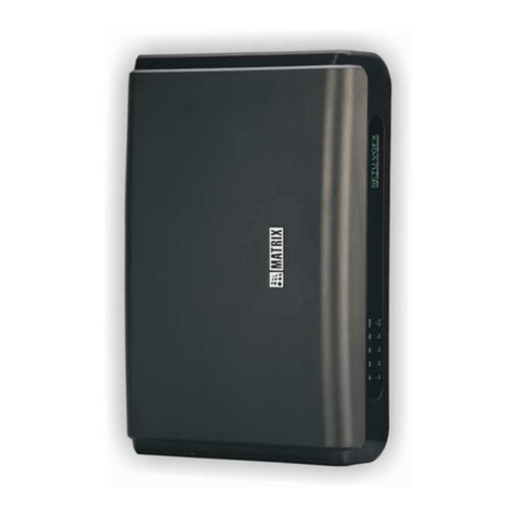
Matrix SETU VTEP User manual

SETU VTEP
Quick Start


SETU VTEP
An Out-n-Out VoIP to T1/E1 Gateway
Quick Start

Documentation Disclaimer
Matrix Comsec reserves the right to change, at any time, without prior notice, the product design,
specifications, components, as engineering and manufacturing may warrant.
This is a general documentation for all models/configurations of the product. The product may not
support some of the features/facilities described in this document.
While every reasonable effort has been made to ensure accuracy of content in this document,
Matrix Comsec assumes no responsibility for errors or omissions that may occur herein. No
liability is assumed for damages, costs, expenses resulting from unauthorized modifications or
repairs to the product; failure to use information or to comply with the installation, operation and
maintenance instructions contained in this document.
Copyright
All rights reserved. No part of this document may be copied or reproduced in any form or by any
means without the prior written consent of Matrix Comsec.
Version V1
Release date: November 17, 2016

Table of Contents i
Contents
Know Your SETU VTEP ................................................................................................... 1
Overview ............................................................................................................................1
Installing SETU VTEP ...................................................................................................... 3
Before you Start .................................................................................................................3
Getting Started ...................................................................................................................3
Connecting SETU VTEP ......................................................................................................4
Power On SETU VTEP .........................................................................................................8
Accessing Jeeves ..............................................................................................................9

ii Table of Contents

Matrix SETU VTEP Quick Start 1
Know Your SETU VTEP
Thank you for choosing the Matrix SETU VTEP. Please read the instructions in this Quick Start to
install and operate SETU VTEP.
This Quick Start is meant to help you install SETU VTEP and access its User Interface for
configuration. For detailed instructions for configuration and feature description, refer the System
Manual. To download, click http://www.matrixtelesol.com/technical-document.html.
Overview

2 Matrix SETU VTEP Quick Start
Ports and Connectors
LED
Port Description
5VDC-2A (Max) Connector for the Power Adapter.
USB Port Unused
Ethernet Port
Ethernet port can be used as
•LAN interface to connect a computer/LAN Switch.
•WAN interface to connect to IP network. You can connect a DSL modem/
Router or a LAN Switch.
T1/E1 Port T1/E1 Port to connect the T1 or E1 line.
SYNC IN & SYNC Out SYNC IN and SYNC Out Ports for synchronizing the system’s clock with that of
the Public ISDN Network.
LED Description
PWR Turns on when power is supplied.
STS Blinks to indicate health of the system.
L1 Indicates the status of layer 1 of the T1/E1 line.
L2 Indicates the status of layer 2 of the T1/E1 line.
SIP Indicates the status of the SIP Trunk to which the LED is
assigned.

Matrix SETU VTEP Quick Start 3
Installing SETU VTEP
Before you Start
• Select a suitable location to mount SETU VTEP.
• Keep the following ready:
• A standalone PC to access the User Interface.
• A SIP Account for VoIP connectivity.
• A T1 or E1 line for ISDN connectivity.
• Do not install this product near any area where
• it is exposed to direct sunlight, heat, excessive cold or humidity, dust, oil, corrosive fumes.
• there is a water source (wash basin, tub, shower, pool, sprinkler, etc.)
• there is source of electromagnetic noise such as radio equipment, heavy transformers,
faulty electric chokes of tube-lights, device having a faulty coil.
• Ensure proper electrical earth and telecom earth for the safety of the product and persons
handling it.
Getting Started
Package Contents
• Unpack the SETU VTEP and check the package contents. The product package must have the
following items:
• SETU VTEP unit
•APowerAdapter
• Two M7/30 screws and screw grips
• One Ethernet cable
• One PRI Cross cable
• A Wall Mounting Template
• A Warranty Card set
• Two 19 inch Rack Mounting Clamp
• SETU VTEP Quick Start (printed copy)
If any of these items is missing or damaged, please contact the dealer/reseller from whom
you purchased the system.
• Place the system at the selected site.

4 Matrix SETU VTEP Quick Start
If you are mounting the system on a wall, you may refer to the mechanical dimensions of the
product and use the mounting template for drilling holes on the wall.
Connecting SETU VTEP
Connecting to the VoIP Network
Before you connect the system to WAN, we recommend that you first connect a computer to the
Ethernet Port of SETU VTEP, configure the Basic Settings, and then connect to WAN.
Use the Ethernet cable supplied for the Ethernet Port of SETU VTEP to connect the system to the
IP network, which may be Public Internet or a LAN.
If connecting to the Public IP Network,
• Plug one end of the RJ45 Ethernet cable into the Ethernet Port of SETU VTEP and the other
end into the Broadband Router/Modem.

Matrix SETU VTEP Quick Start 5
If connecting to a Private Network (Behind a NAT Router),
• Plug one end of the RJ45 Ethernet cable into the Ethernet Port of SETU VTEP and the other
end into the LAN Switch/Hub.
Connecting to the ISDN Network
• By default, the T1/E1 Port is set for E1 Line connectivity.
• Connect the T1 or E1 line from your Service Provider / an ISDN PBX to the T1/E1 port of SETU
VTEP, according to your installation requirement.
Illustrated below is a typical connection of a T1/E1 line to the T1/E1 port of SETU VTEP.
Here, the SETU VTEP is the Terminal Equipment, so the Orientation Type of the T1/E1 port
must be configured as Terminal. For more details, refer the E1 Port and T1 Port topics under
Basic Settings in the System Manual.
Refer the following pin details for connecting the Network Termination Unit with the T1/E1
Por t of SETU VTEP.

6 Matrix SETU VTEP Quick Start
Pin details of HDSL Interface of the G.703 Modem (HDSL Network Termination Unit)
Pin details of DTE Interface of G.703 Modem (HDSL Network Interface Unit)
• The pin out details of the HDSL interface and DTE interface are of a stand-alone HDSL Network
Termination Unit; the Model HTU-E from RAD Data Communication. Most of the HDSL Network
Termination Unit manufacturers use these connectors. But you are advised to read the
installation guide of the HDSL Network Termination Unit you are using.
• You may use PRI Cross cable depending on the pin out of the DTE Interface of the terminal.
Pin Number Pin Details
1Line A
2Line A
3Not used
4Line B
5Line B
6Not used
7Not used
8Not used
Pin Number Pin Details
1TX1 (Tip)
2TX2 (Ring)
3Not used
4RX1 (Ring)
5RX2 (Tip)
6Not used
7 Not used
8Not used

Matrix SETU VTEP Quick Start 7
Pin details of the T1/E1 Port of SETU VTEP
Connecting SYNC IN and SYNC Out Ports
The SYNC IN and SYNC OUT ports of SETU VTEP are used for synchronizing the system’s clock
with that of the Public ISDN Network to prevent possible clock slips that affect voice quality.
Clock synchronization becomes necessary when the T1/E1 Port is in Network mode and no direct
T1 or E1 line from the Public ISDN Network is terminated in the SETU VTEP.
See the figure below for connecting the SYNC IN and SYNC OUT ports for Network Clock
synchronization.
The T1/E1 Line from the Public ISDN Network is connected to the SYNC IN port of SETU VTEP
and the same line emerges from SYNC OUT port and is terminated on the T1/E1 (TE) port of the
PBX.
Pin Function
1Receive Data Input Rx1
2Receive Data Input Rx2
3Not connected
4Transmit Data Output Tx1
5Transmit Data Output Tx2
6Not connected
7Not connected
8Not connected

8 Matrix SETU VTEP Quick Start
Here, the T1/E1 port of the ISDN PBX is the ‘Terminal’ and the T1/E1 Port of the SETU VTEP to
which it is connected is the ‘Network'. So, the Orientation Type of the T1/E1 Port of the SETU
VTEP must be configured as Network.
Power On SETU VTEP
•Connectthepoweradapter to SETU VTEP.
• Plug in the power adapter of SETU VTEP into the power outlet.
• Switch on power supply and wait for the Reset Cycle to complete.
Reset Cycle
The Reset Cycle (Power-ON Self Test) takes about 2 minutes to finish.
LED Indication - Reset Sequence
LED Indication - SIP Trunk
System Status Color L1 L2 STS Time in msec
Application Load Green On Off On 200ms
All Init Done, System
goes live Green On On On 1000ms
Red On On On 1000ms
Off Off Off 1000ms
Green Off On Off 1000ms
Off Off Off
1000ms
(Continuous
Last 2 steps)
Event/State/Status Color Cadence (1 cadence is of 4000msec)
ON OFF ON OFF
SIP Disable OFF
SIP Registered (Active) Green Continuous
SIP Registration Failed Red Continuous
SIP Authentication Failed Red 200 200 200 3400

Matrix SETU VTEP Quick Start 9
Accessing Jeeves
You may now access the web-based programming tool, Jeeves, for configuration. To access
Jeeves, you will need to connect a computer to SETU VTEP.
Connecting a Computer
You may connect a standalone computer to SETU VTEP or grab any computer connected in the
same LAN as SETU VTEP.
Connect a standalone computer to SETU VTEP, when installing the system for the very first time. You
may connect it to a computer on LAN at a later stage, once you have finished installation and
configuration of the system.
Make sure a web-browser, either Internet Explorer (Version 7 or higher) or Mozilla Firefox (Version
3.5 or higher), is installed on your computer.
To connect a standalone computer,
• Plug one end of the Ethernet cable supplied into the Ethernet Port of SETU VTEP. Plug the
other end into the LAN port of the computer.
• Make sure the IP Address of the computer and the Ethernet Port of SETU VTEP do not
conflict, and that both are in the same Subnet.
The default IP Address of the Ethernet Port of SETU VTEP is 192.168.1.100 and the default
Subnet Mask is 255.255.255.0.
• Change the Subnet of the computer, if necessary.
• Open the recommended web-browser (Internet Explorer or Mozilla Firefox).
Computer
Ethernet Port

10 Matrix SETU VTEP Quick Start
• Enter the default IP address 192.168.1.100 of the Ethernet Port of SETU VTEP in the address
bar of the browser.
• You will be redirected to the HTTPS protocol for security reasons.
•Clickthehttps://192.168.1.100 link.
•TheLogin page will open.
•InLogin Password, enter 1234, the default SE Password.
•ClicktheLogin button.

Matrix SETU VTEP Quick Start 11
• You will be prompted to change the default SE Password.
•InCurrent Password, enter the default SE Password.
• Enter the New Password. All ASCII characters (except Percentage %, Hash #, Equal to =,
Plus +, And &, Backslash \, Less than <, Greater than >, Apostrophe ’ , Double Quote "and
Space) and digits 0to 9are allowed. The new password must be:
• a minimum of 6 characters to a maximum of 16 characters.
• include atleast one upper-case, one lower-case, one number and one special character.
•InConfirm New Password, re-enter the new password to confirm.
• Click Submit. You will be re-directed to the Login page again.
•InLogin Password, enter the new password.
As this password is meant for restricting access to the SE mode, we strongly recommend you to:
• Keep the password secret.
• Select a complex password that cannot be easily guessed.
• Change the password regularly. See Login Password topic in the System Manual for
instructions.

12 Matrix SETU VTEP Quick Start
On successful login, the home page of Jeeves opens.
On the left navigation bar the following links appear:
•Basic Settings: Sufficient to get your system into operation.
•Advanced Settings: Enable you to configure the advanced features and facilities of SETU
VTEP.
•Maintenance: Allows you maintenance and monitoring tasks—uploading configuration
and firmware, system debug, system restart.
•Status: Allows you to view the system details and status of all the SIP trunks, T1/E1
Layer and the Network port.
• You may now configure the Basic Settings of SETU VTEP.
You may use the configuration Wizard or selectively configure the Basic Settings pages,
whichever works best for you. Refer the SETU VTEP System Manual for detailed instructions.

Matrix SETU VTEP Quick Start 13

Version 1, November 2016
MATRIX COMSEC
Head Office
394-GIDC, Makarpura, Vadodara - 390010, India.
M: +91 85111 73344
E-mail: Customer.Care@MatrixComSec.com
www.MatrixTeleSol.com
Table of contents
Other Matrix Gateway manuals

Matrix
Matrix SETU VGFX User manual

Matrix
Matrix simado gfx11 User guide

Matrix
Matrix SETU ATA211 SIP-FXS-FXO User guide

Matrix
Matrix SETU VFX88L User manual

Matrix
Matrix SIMADO GFX44 User manual

Matrix
Matrix SETU VFX User manual

Matrix
Matrix SIMADO GFX44 User guide

Matrix
Matrix SETU VFXTH User guide

Matrix
Matrix SETU VG User guide
Matrix
Matrix SETU VFX88L User guide
Popular Gateway manuals by other brands

Badger Meter
Badger Meter ORION Fixed Network SE Application data

RTA
RTA 460BCSC-NNA4 Product user guide

RTA
RTA 460ECPS-N2E Product user guide

hilscher
hilscher netTAP NT 50 Series user manual

ZyXEL Communications
ZyXEL Communications EMG2881-T20A user guide

HMS Networks
HMS Networks Intesis IN770AIR00XO000 user manual