Maxon MCB-45W User manual

MCB-45W
Deluxe Mobile CB/
Weather Radio
OWNER'S MANUAL
E glish/Spa ish


Before operating your Maxon Citizens Band Radio,
read this Owner's Manual carefully. If you have a
pro lem, refer to the "Trou leshooting" section of
this manual efore returning your radio for repairs.
TABLE OF CONTENTS
Product Description 1
FCC Regulations 1
Performance Features 2
Package Contents 3
Controls and Functions 4
Installation Instructions 6
Mechanical Mounting 7
Power Supply Connection 8
Mo ile Antenna Information 9
Antenna Tuning Information 10
Operating Instructions 11
To Use Emergency Channel 9 11
PA System / PA Speaker Operation 12
External Speaker Operation 12
Using the Weather Channels 12
Radio Communication Codes 14
CB Channel Frequency Chart 15
Trou leshooting Chart 16
Specifications 17
Other Maxon Products 18
Warranty Service Instructions 19
Warranty Statement 20

Antes de hacer funcionar su radio de Maxon lea
detenidamente este Manual del Propietario. Si tiene
unpro lema, refiérase a la sección "Localización y
Reparación de Averías" de este manual antes de
devolver su radio para la reparación.
TABLA DE CONTENIDO
Controles y Funciones 4
Descripción del Producto 21
Regulaciones de la FCC
(Comisión Federal de Comunicaciones) 21
Características de Funcionamiento 22
Contenido del Paquete 23
Instrucciones Para Instalación 24
Montaje Mecánico 25
Conexión del Suministro Energético 26
Información So re la Antena Móvil 27
Información Para la Sintonización de
la Antena 28
Instrucciones de Operación 29
Para usar el Canal 9 de Emergencia 30
Operación del Sistema de Altoparlante (PA) 30
Operación de los Altoparlantes Exteriores 30
Uso de los Canales Meteorológicos 31
Ta la de Frecuencia del Canal de CB
(Banda Ciudadana) 33
Ta la de Localización y Reparación
de Averías 34
Especificaciones 35
Otros Productos Maxon 36
Instrucciones Servicio de Garantía 37
Aclaración de la Garantía 38

1
PRODUCT DESCRIPTION
Thank you for choosing the Maxon
MCB-45W Mobile CB/Weather Radio.
The MCB-45W is a compact mo ile Citizen's
Band radio designed to operate in the 26.965 to
27.405 MHz and.
This unit features 10 weather channels, including
7 NOAA frequencies and 3 international marine
frequencies. The MCB-45W provides maximum
RF output power and many automatic features to
enhance voice clarity and sound quality.
Enjoy your new Maxon CB!
YOU DO NOT NEED AN FCC LICENSE TO
OPERATE THIS RADIO IN THE UNITED STATES.
However, you must k ow a d be familiar with
Part 95 of the FCC Rules i regard to Subpart D
of the Citize s Ba d Radio Service. (A copy is
enclosed with the unit.)

2
PERFORMANCE FEATURES
• Maximum legal RF output power (4 W) with high
level modulation (in accordance with FCC Part
95 Rules)
• Compander circuitry eliminates ackground static
and improves audio quality
• Receives current local National Weather Service
and periodic marine weather roadcasts
• Direct access to Emergency Channel 9
• Pu lic Address capa ility
• LCD channel display indicates: the CB or
Weather Channel selected, "9 EMG" when in
Emergency Channel 9 position, or "PA" when
in Pu lic Address system mode
• Switcha le Automatic Noise Limiter (ANL)
circuit reduces atmospheric static noise
• Signal / Power LCD meter shows the incoming
signal strength, and the RF output power
• RF Gain control adjusts the receiver sensitivity
of the radio
• Side mounted 4-pin universal microphone with
coiled cord and easy to operate Push-To-Talk ar
• Equipped with external speaker jack - external
speaker not included
•Last channel memory recalls last channel
displayed
•One year warranty

3
PACKAGE CONTENTS
Main CB unit
Handheld microphone
CB Mounting racket and hardware
Owner's manual
Copy of FCC Part 95, Su part "D"
Copy of NOAA Weather Radio Network
frequency card
An external mo ile antenna is required for use -
antenna is not included. Refer to Mo ile Antenna
Information section for more information.

4
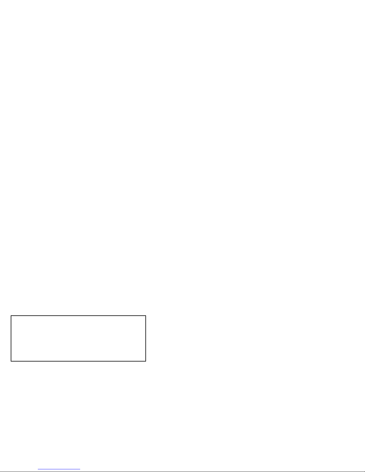
CONTROLS AND FUNCTIONS
CONTROLES Y FUNCIONES
A) Micropho e a d Cord • Micrófo o y Cable
B) Weather Butto - Selects CB or weather opera-
tion • Botó del Tiempo - Selecciona la operación
de CB o del tiempo
C) Emerge cy Cha el 9 Butto - Provides direct
access to Emergency Channel 9 (not active in
weather mode) • Botó del Ca al 9 de Emerge cia -
Provee acceso directo al Canal 9 de Emergencia (no
está activo en modalidad meteorológica)
D) ANL Butto - Activates Automatic Noise Limiter
(ANL) circuitry • Botó ANL: Activa los circuitos
del limitador automático de ruidos (ANL)
E) PA Butto - Activates the Pu lic Address (PA) system
circuitry • Botó PA: Activa los circuitos del sistema
de altoparlante (PA)
F) LCD Display - Identifies CB or weather channel
num er selections, TX (transmit), WX (weather) mode,
EMG (Ch. 9), PA, and signal/power strength
• Pa talla de LCD - Identifica las selecciones
de CB o los números de canales del tiempo, TX
(transmisión), modalidad de WX (tiempo), EMG
(Canal 9), PA, e intensidad de la señal/potencia
G) CB/Weather Cha el Co trol - Selects CB or weather
channel • Co trol Para CB/Tiempo - Selecciona la
canales de CB o del tiempo
H) RF Gai Co trol - Adjusts the receiving sensitivity of
the radio • Co trol de Ga a cia RF: Ajusta la
sensi ilidad de recepción de la radio
I) Squelch Co trol • Co trol para Amortiguar Ruidos
J) Off/O -Volume Co trol - Used to turn the radio
on or off and to adjust the listening volume
• Co trol de Volume - Se usa para encender
o apagar el radio y para ajustar el volumen

5
K) A te a Jack - Connects a mo ile CB antenna
(PL-259) • Co ector para A te a - Conecta la antena
movil de anda ciudadana (PL-259)
L) Public Address (PA) Speaker Jack - Connects an
optional remote mounted PA speaker • Co ector
para Altoparla te de Sistema de Altoparla te (PA) -
Permite conector un altoparlante remoto opcional
M) DC Power Cord • Córdo de Pote cia DC
N) Exter al Speaker Jack • Co ector Para Altoparla te
Exter o
N M L K
A
F
J I H G
B C D E

INSTALLATION INSTRUCTIONS
Your new MCB-45W is designed to e installed
under the dash or anywhere inside your vehicle.
It can e mounted horizontally or vertically. Safety
and convenience should e your primary consider-
ations in deciding exactly where to locate your
Maxon MCB-45W CB Radio.
CAUTION: Be sure the u it is located where
it will ot i terfere with the driver or impair
access to a y co trols ecessary for the safe
drivi g of the vehicle. The radio's power or
antenna connecting ca les must e routed and
secured in such a manner as not to interfere with
the operation of the rake, accelerator or other
controls. Interference from either the CB unit or
it's connecting ca les may contri ute to the loss
of control of the vehicle.
I stalli g the MCB-45W:
6

Mecha ical Mou ti g
1) Determine the mounting location of your
MCB-45W.
2) Use the CB ca inet mounting racket as a
template for marking the location of the screw
holes when mounting the CB under the dash,
or at another selected location.
3) Drill the necessary holes and secure the
mounting racket with the self-tapping
screws provided.
CAUTION: EXTREME CARE SHOULD BE
EXERCISED WHEN DRILLING UP INTO
THE DASH to avoid a y damage to i -dash
electro ic ig itio wiri g, cruise co trol,
i strume ts or accessory wiri g.
4) Position the CB unit etween the mounting
racket arms (in line with the retention kno s).
Set the CB unit angle for the est operating
comfort and control accessi ility. Tighten the
two retention kno s to secure the CB unit in
place.
5) Install the microphone hanger racket utilizing
the pre-drilled mounting holes in the ca inet,
or attach the racket to the vehicle dash or
another convenient location.
6) If you choose to mount the CB in a location
where self-tapping screws cannot e used,
determine the most secure method of fastening
the CB ca inet.
7

Power Supply Co ectio
The MCB-45W is designed for 12V DC operation
in vehicles with NEGATIVE (-) GROUND electrical
systems. Most domestic and foreign made cars and
trucks use a negative ground system. NOTE: If your
negative (-) attery terminal is connected to the
motor lock of your vehicle, it is a negative ground
system.
CAUTION: Do ot attempt to co ect your
MCB-45W to a POSITIVE (+) grou d vehicle
as damage may occur to the CB u it a d/or to
your vehicle's electrical system.
NOTE: Check your vehicle's ground requirements
efore you egin the installation!
Your MCB-45W should e connected using the
following steps:
1) Move the off/on-volume control to the "off"
position. CAUTION: If the off/o -volume
co trol is i the "o " positio without a
a te a hook-up, it could result i damage
to the tra smitter circuitry.
2) Disconnect the ca le from your vehicle
attery's negative (-) terminal.
3) Connect the black GROUND wire to a metal
part of your vehicle's frame.
NOTE: Be sure the metal part is ot i sulated from
the vehicle's frame by a plastic part.
4) Connect the red (to switched accessory) wire
to a source of voltage that turns on and off with
the ignition switch, such as a spare accessory
terminal in your vehicle's fuse ox.
8

9
5) Connect the ora ge (Batt +) wire to your
vehicle's attery positive (+) terminal or to
a point in the vehicle's fuse ox that provides
a continuous source of 12 Volts even when
the ignition is turned off. This connection
provides last channel memory feature.
6) Reconnect the ca le to the vehicle's attery
negative (-) terminal.
MOBILE ANTENNA INFORMATION
Your Maxon MCB-45W requires a vehicle mount
CB antenna for operation. An antenna is not included
with your radio ecause of varying vehicle applica-
tions, individual needs, and owner cost preferences.
Maxon antenna model WTA-4WP may e o tained
from your local Maxon CB distri utor / retailer or
you may use any standard 50 Ohm vehicle mount
CB/weather antenna with a PL-259 connector.
NOTE: When installing a mo ile antenna, please
follow the antenna manufacturer's installation
instructions completely. Never operate your CB
radio without a a te a or with a broke a te a
cable. This can result in damage to your CB trans-
mitter circuitry.
•Connect the antenna securely to the radio's
antenna receptacle.
•Mount the antenna as high on the vehicle as
possi le - the more the antenna extends a ove
the roof, the etter the reception. If possi le,
mount the antenna in the center of the surface.
•Keep the antenna ca les away from noise sources
such as the ignition system, gauges, etc.
•Make sure you a have solid, metal-to-metal
ground.

ANTENNA TUNING INFORMATION
Most antennas are factory tuned, ut performance
can usually e improved y slightly lengthening or
shortening the antenna using a Standing Wave Ratio
(SWR) meter (not included). Refer to the antenna
manufacturer's installation manual for the exact
procedure to tune the antenna. You can purchase
an SWR meter, or have your antenna checked y
your CB Dealer's service department.
10

11
OPERATING INSTRUCTIONS
Once you have properly wired your new CB and
connected the antenna, you are ready to adjust your
radio for optimum reception and voice transmission.
For proper operation, the radio's microphone must e
connected to the unit. Insert the microphone plug
into the microphone jack (MIC). Push inward and
tighten the locking nut on the end of the cord. When
removing the microphone, unscrew the locking nut
and ge tly pull out the microphone plug
1) Turn the off/on-volume control clockwise and
adjust to a comforta le volume level.
2) Use the CB/Weather channel control kno
to select the desired channel.
3) Adjust the squelch control kno to reduce any
undesira le ackground noise when no signal
is eing received. To do this, select a channel
where no signals are present, or wait until
signals cease on your channel. Then, rotate
the squelch control kno clockwise to a point
where the ackground noise ceases.
NOTE: When the squelch is set properly, the radio
speaker will remain quiet until a signal is received.
In order to receive weak signals, do not set the
squelch too high.
4) Re-adjust the volume to a desired listening level.
To use Emerge cy Cha el 9
Press the CH9 selector. "9EMG" will display on the
LCD. Press CH9 again to return to normal CB mode.

12
To Tra smit: Press and hold the Push-To-Talk ar.
Speak slowly and clearly in a normal voice, placing
the microphone approxamately two to three inches
away from the mouth. The radio's uilt-in modula-
tion control circuit will automatically adjust the
microphone input level. There is no need to speak
loudly.
To Receive: Release the Push-To-Talk ar.
PA System / PA Speaker Operatio
To use the Pu lic Address feature, you must install
a remote mounted PA speaker (not supplied). After
the speaker is installed, insert the speaker's wired
connector plug into the PA speaker jack on the ack
of the CB unit. To activate the PA system circuitry,
press the PA selector. At this time you will no
longer e a le to send, or receive CB transmissions.
You are now ready to roadcast through the PA
speaker using the radio's microphone and volume
control. Press the PA selector to return to normal CB
operation.
Exter al Speaker Operatio
To connect an optional external speaker, locate the
external speaker jack on the rear of the unit and
insert the speaker plug into the jack. The radio's
internal speaker will e silenced when an external
speaker is engaged.
USING THE WEATHER CHANNELS
The National Weather Service uses several special
radio frequencies to provide continuous reports of
local weather conditions and forecasts throughout
the United States. Taped weather messages are
repeated every four to six minutes on a 24-hour

asis and are routinely revised every one to three
hours, or more frequently if needed.
During severe weather, the routine weather road-
casts will e interrupted with special weather
warning messages.
The MCB-45W is designed to receive all of these
special weather frequencies plus three international
marine frequencies. A NOAA Weather Radio
Network Frequency card is enclosed to identify
the frequencies specifically roadcast for your
geographical area. The MCB-45W receives CB,
National Weather Service and international marine
weather roadcast frequencies as listed:
CB Cha els 1 - 40 (26.965 - 27.405 MHz)
Weather Cha el 01 WX 162.550 MHz
02 WX 162.400 MHz
03 WX 162.475 MHz
04 WX 162.425 MHz
05 WX 162.450 MHz
06 WX 162.500 MHz
07 WX 162.525 MHz
I t'l Mari e 08 WX 161.650 MHz
09 WX 161.775 MHz
00 WX 163.275 MHz
To Operate: Turn the off/on-volume control clock-
wise and press the weather utton. The "WX" icon
will e displayed.
Use the weather frequency card to select the proper
frequency for your area. Select the weather channel
y using the channel up/down uttons. Re-adjust the
volume if necessary.
To retur to CB operatio , simply press the weather
utton again; the "WX" icon will disappear and the
unit will return to the last CB channel displayed.
13

14
Code Descriptio
10-35 Confidential information.
10-36 Correct time is________.
10-37 Wrecker needed at ____.
10-38 Am ulance needed at__.
10-39 Your message delivered.
10-41 Please turn to channel_.
10-42 Traffic accident at______.
10-43 Traffic tie-up at________.
10-44 I have a message for you.
10-45 All units within range
report.
10-50 Break channel.
10-60 What is next message
num er?
10-62 Una le to copy; use phone.
10-63 Network directed to.
10-64 Network clear.
10-65 Awaiting your next
message/assignment.
10-67 All units comply.
10-70 Fire at _______________.
10-71 Proceed with transmission
in sequence.
10-77 Negative contact.
10-81 Reserve hotel room at___.
10-82 Reserve room for_______.
10-84 My telephone num er is_.
10-85 My address is_________.
10-91 Talk closer to microphone.
10-93 Check my frequency on
this channel.
10-94 Please give me a long
count.
10-99 Mission completed; all
units secure.
10-200 Police needed at_______.
Receiving poorly.
Receiving well.
Stop transmitting.
OK, message received.
Relay message.
Busy, stand y.
Out of service; leaving
the air.
In service, su ject to call.
Repeat message.
Transmission completed,
standing y.
Talking too fast.
Visitors present.
Advise weather/
road conditions.
Make pickup at_______.
Urgent usiness.
Anything for us?
Nothing for you;
return to ase.
My location is_______.
Call y telephone.
Report in person to_____.
Stand y.
Completed last assignment.
Can you contact?
Disregard last information.
I am moving to channel_.
Identify your station.
Time is up for contact.
Does not conform
to FCC rules.
I will give you a radio check.
Emergency traffic.
Trou le at this station.
RADIO COMMUNICATION CODES
Citizens Band radio operators have universally adopted
the "10" Code for standard questions and answers. It
ena les them to communicate faster, easier and more
understanda ly in noisy surroundings.
The following are some of the most common codes and
their descriptions.
When using the code 10-1, you would say, "Ten one",
not "One zero dash one".
Code Descriptio
10-1
10-2
10-3
10-4
10-5
10-6
10-7
10-8
10-9
10-10
10-11
10-12
10-13
10-16
10-17
10-18
10-19
10-20
10-21
10-22
10-23
10-24
10-25
10-26
10-27
10-28
10-29
10-30
10-32
10-33
10-34

Channel:
15
CB CHANNEL FREQUENCY CHART
26.965 MHz
26.975 MHz
26.985 MHz
27.005 MHz
27.015 MHz
27.025 MHz
27.035 MHz
27.055 MHz
27.065 MHz Emerge cy Cha el
27.075 MHz
27.085 MHz
27.105 MHz
27.115 MHz
27.125 MHz
27.135 MHz
27.155 MHz
27.165 MHz
27.175 MHz
27.185 MHz Highway Cha el
27.205 MHz
27.215 MHz
27.225 MHz
27.255 MHz
27.235 MHz
27.245 MHz
27.265 MHz
27.275 MHz
27.285 MHz
27.295 MHz
27.305 MHz
27.315 MHz
27.325 MHz
27.335 MHz
27.345 MHz
27.355 MHz
27.365 MHz
27.375 MHz
27.385 MHz
27.395 MHz
27.405 MHz
1
2
3
4
5
6
7
8
9
10
11
12
13
14
15
16
17
18
19
20
21
22
23
24
25
26
27
28
29
30
31
32
33
34
35
36
37
38
39
40

No sound or LCD lights
LCD illuminated, ut no sound
No voice reception
Poor reception
Unclear reception
Transmission pro lems
This mo ile Citizens Band radio has een
manufactured in accordance with Maxon's
exacting quality control
standards. It should e
handled with reasona le
care. Avoid exposing it
to dirt or moisture.
If you experience
pro lems, please
refer to this
Trou leshooting
Chart.
TROUBLESHOOTING CHART
16
POSSIBLE PROBLEMS:
WARNING: DO NOT ATTEMPT TO MAKE ANY INTERNAL
ADJUSTMENTS. Internal adjustments and/or modifications can
lead to illegal operation as defined y FCC Rules and Regulations,
Part 95. They must e made only y qualified technical personnel.
Illegal operation can result in serious consequences.
CAUTION: The fuse included with this unit is an important safety
feature which must ot e circumvented. Removal of this fuse
or the use of a fuse rated higher tha supplied may result i
overheati g a d/or fire a d co seque tial damage to the u it
or vehicle. If a replacement fuse urns out, have the unit inspected
and repaired y a qualified service technician.
Check power ca le connection
Check fuses (in-line and main junction lock)
Check squelch adjustment
Check power off/on-volume control
Change to active channel
Check antenna connection
Fully depress push-to-talk ar when speaking
Check microphone connection
POSSIBLE SOLUTIONS:
Table of contents
Languages:
Other Maxon Radio manuals

Maxon
Maxon SD125E Series User manual

Maxon
Maxon SP-130 Series User manual

Maxon
Maxon SP-510 User manual

Maxon
Maxon SM5402 User manual

Maxon
Maxon SM5102 User manual

Maxon
Maxon PM200 User manual

Maxon
Maxon SP-6102 User manual

Maxon
Maxon HCB-40WX User manual

Maxon
Maxon SM-2000E Series User manual

Maxon
Maxon MCB-30 User manual

Maxon
Maxon MCB-100 WXD User manual

Maxon
Maxon EM-4800 User manual

Maxon
Maxon SD-160 Series User manual

Maxon
Maxon MDP-6000 Series User manual

Maxon
Maxon sm-2000 series User manual

Maxon
Maxon TM-4800 User manual

Maxon
Maxon CM10 User manual

Maxon
Maxon SP-200 Series User manual

Maxon
Maxon CM10 User manual

Maxon
Maxon TJ-3000 Series User manual