7
[FR] MODE D’EMPLOI
Merci d’avoir acheté ce radiateur infrarouge. Nous espérons que vous serez complètement
satisfait de ce produit. Pour ce faire, veuillez lire attentivement ces instructions avant utilisation et
conservez-les dans un endroit sûr.
ATTENTION
- Ne laissez pas un appareil de chauffage sans surveillance, surtout si des enfants ou des
animaux domestiques sont présents.
- Les chauffages au gaz ou au pétrole doivent être correctement ventilés. Par conséquent,
il ne faut pas boucher toutes les ssures. Sinon, il y a un risque d’empoisonnement au CO.
- Soyez prudent avec les appareils de chauffage, ne posez rien dessus et tenez-les à une
distance sûre des objets inammables.
- N’utilisez que des appareils électriques dont le cordon est sécurisé.
- Éteignez les appareils que vous n’utilisez pas, surtout si vous dormez ou si vous n’êtes pas chez
vous.
- Vériez régulièrement votre appareil de chauffage. Une installation qui fonctionne mal
peut entraîner au feu.
AVERTISSEMENTS
■ Cet appareil électrique est conforme aux normes de sécurité technique et de compatibilité
électromagnétique.
■ Ne touchez jamais votre appareil de chauffage lorsqu’il est en marche (risque de brûlure).
■ Ne le touchez jamais avec les mains mouillées.
■ Ne faites jamais tourner la partie chauffante de l’appareil en cours de fonctionnement. Pour
changer l’angle d’attaque de la partie chauffante, nous vous conseillons d’attendre 15 minutes
après la mise hors tension de l’appareil.
■ Ne placez jamais d’objet sur le dispositif de protection de votre appareil de chauffage car cela
pourrait provoquer une surchauffe (serviettes, par exemple).
N’utilisez jamais votre appareil pour le lavage à sec.
■ Bien que l’élément chauffant ait cessé de briller, il peut rester vivant et potentiellement
dangereux. Vériez que l’indicateur de sélection (5) est éteint avant d’agir.
■ Eteignez votre appareil:
- Après utilisation
- En cas de dysfonctionnement
- Avant de le nettoyer.
■ Ne faites jamais fonctionner votre appareil s’il est tombé.
■ Ne démontez jamais votre appareil. Un appareil mal réparé peut être dangereux pour
l’utilisateur. Si vous rencontrez des problèmes, veuillez vous adresser à l’un des centres de
service agréés de notre réseau de services après-vente.
■ La garantie sera annulée en cas de dommages résultant d’une utilisation incorrecte.
■ N’utilisez pas cet appareil de chauffage à proximité immédiate d’un bain, d’une douche ou
d’une piscine.
■ Cet appareil mobile est conçu pour une utilisation dans les jardins et peut être utilisé à l’intérieur
et à l’extérieur. La garantie ne s’appliquera pas aux appareils utilisés à des ns professionnelles.
Bien que l’appareil de chauffage puisse être utilisé à l’extérieur, la che principale ne doit être
raccordée qu’à l’alimentation.
■ L’appareil de chauffage est doté d’un interrupteur anti-inclinaison qui l’éteindra s’il est renversé
et le rallumera automatiquement lorsqu’il sera rétabli.
■ Les instruments dans la hauteur d’installation minimale de 1,8 mètres.
■ Cet appareil n’est pas destiné à être utilisé par des personnes (y compris des enfants) ayant
des capacités physiques, sensorielles ou mentales réduites ou un manque d’expérience et de
connaissances à moins qu’elles ne soient supervisées ou aient reçu des instructions sur la façon
d’utiliser l’appareil par une personne. responsable de leur sécurité.
■ Les enfants doivent être surveillés pour s’assurer qu’ils ne jouent pas avec l’appareil.
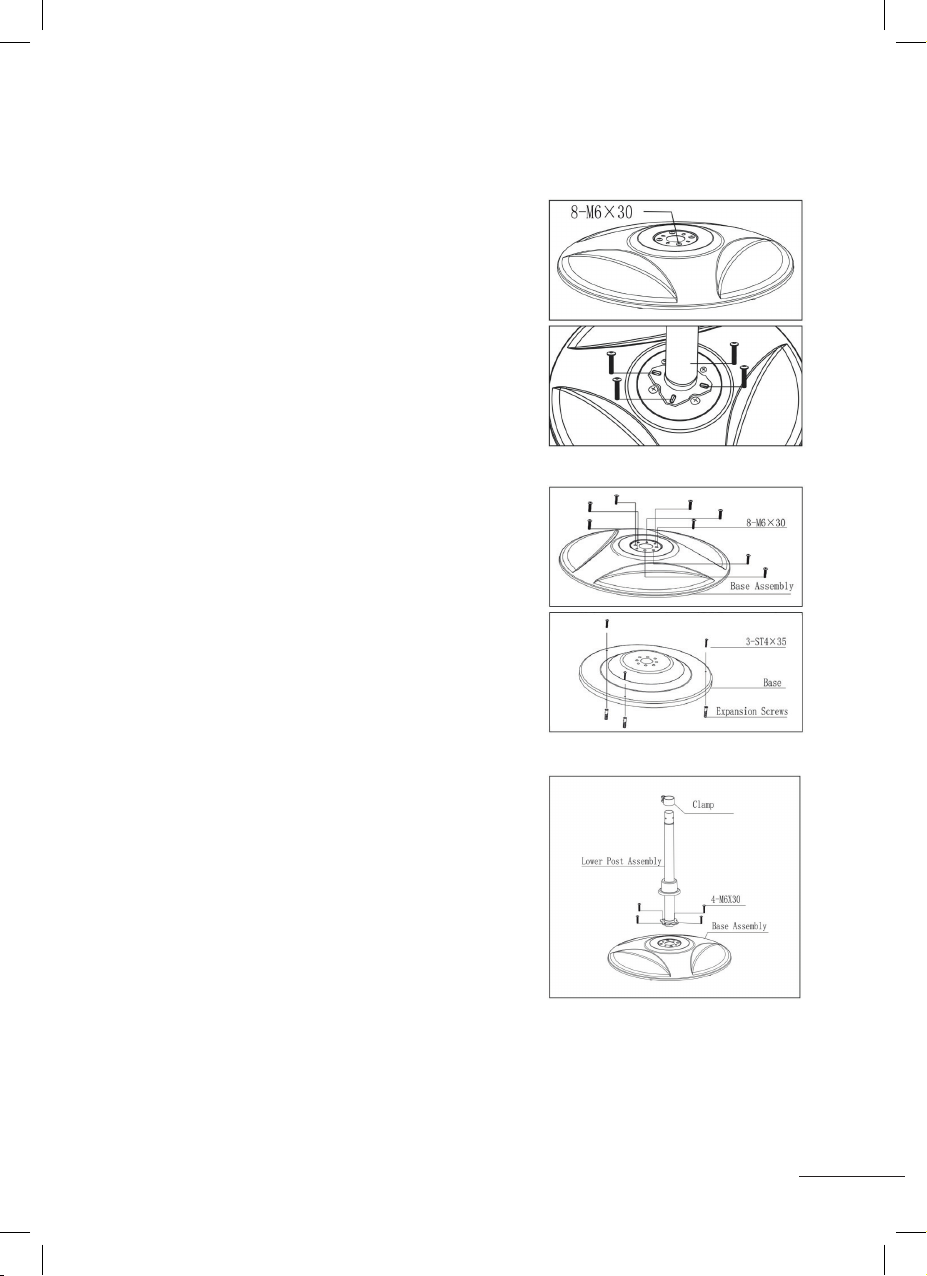
3. Connect the lower post assembly (11)
to the base assembly (16) aligning the 4
holes, and fix it tightly by 4 pcs M6X30
screws. Slide the base cove (14) down so it
covers the screws at the bottom. Place one
of clamp (12) at the top of the lower post
(11).
4. Attach the Middle Post (9) to the Lower
Post Assembly (11).Line up the three holes
that will fix with 3 pcs M5X6 screws to hold
securely.
5. Add the other clamp (12), and secure
the Upper Post Assembly (7) and the
Middle Post (9) together with 3 pcs M5X6
screws.