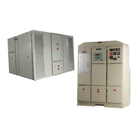
Medha MEP 660 Programming manual

MEP 660 - Trouble shooting Manual
Doc No.: IM – 51 Rev.2.0 Print: October 2008
TROUBLE SHOOTING MANUAL
MICROPROCESSOR BASED
LOCOMOTIVE CONTROL SYSTEM
MEP 660
FOR DIESEL ELECTRIC LOCOMOTIVES
As Per
RDSO Specification No. MP.0.24.00.26 Rev. 0.3 November 2005
P- 4 / 5 B, I.D.A NACHARAM
HYDERABAD - 500 076
Ph. No. 040- 2717 3990 Fax. 040 2717 4908
Email: marketing@medhaindia.com URL: www.medhaindia.com

MEP 660 - Trouble shooting Manual
Doc No.: IM – 51 Rev.2.0 Print: October 2008
CONTENTS
DESCRIPTION PAGE
1.0 INTRODUCTION 1 - 3
2.0 HIGH PRIORITY FAULT MESSAGES 4-116
3.0 MEDIUM PRIORITY FAULT MESSAGES 117-178
4.0 LOW PRIORITY FAULT MESSAGES 179-260
5.0 ONLY ERROR LOG MESSAGES 261-279
6.0 Annexure-1 280-281
7.0 Annesure-2 282
8.0 Annesure-3 283-284
9.0 Annesure-4 285
10.0 Revision sheet 286

MEP 660 - Trouble shooting Manual
Doc No.: IM – 51 Rev.2.0 Print: October 2008 1
1.0 INTRODUCTION
The Microprocessor Based Locomotive Control system MEP 660 continuously monitors
operating levels of various parameters like currents, voltages, temperatures, pressures,
PMs etc. and status of all Auxiliary and main contacts of Contactors. The MEP 660
identifies any abnormal working conditions of any equipment that can indicate a fault in
that equipment. Various faults that are identified are given in the Fault Manual document
No. IM 10 issued by M/S Medha Servo Drives. On identification of any such fault, an
appropriate control action is taken instantly to avoid damage to traction equipments. A
fault message, along with any restriction applied due to the fault, is displayed on the
display unit for guiding the driver. The fault is recorded in the error log along with date
and time stamp. Eight data packs of various locomotive parameters are recorded from 5
seconds prior to the occurrence of fault to three seconds after the occurrence of fault @
one data pack every second. These data packs help the maintenance staff later for
analysis of how the fault has developed and also helps analyse complicated faults.
The classification of these faults and their reset procedure are given in Annexure – 1 for
easy reference
This trouble-shooting manual provides information like restrictions imposed by the fault,
probable causes that can cause the fault and the remedial actions to isolate the fault. The
isolation procedures are written for each and every fault message Identified and listed in
the above Fault Message Manual. No troubleshooting guide is required for the fault
recovery messages that are listed in the Fault Message Manual.
There are 19 cards / modules in the MEP 660 control unit. These modules are plug in
type and inserted in the corresponding slots. Through out this manual the slots are
assumed as 1 to 19, from left to right. The card type No. is labeled both on the card and
MEP-660 control unit to avoid wrong insertion of card. A list of cards and their location of
slots are given as Annexure-2
In this manual an attempt is made to explain step by step procedure to isolate the fault
both in locomotive and as well as MEP 660 components. The trouble-shooting manual has
been discussed anticipating that the user has got basic concept on the locomotive,
through knowledge on MEP 660 components and their functionality. It is recommended
that the user should read the system manual document No. 08 and schematics of MEP
660 document No. ED1000 before this document is used.
In the step by step procedure of fault isolation, the user has been asked to perform
Manual testing of inputs and outputs through display unit wherever necessary to find the
status of digital inputs/outputs and proper functioning of out put devices. The procedure
for Manual testing of inputs and outputs are described in the System Manual document
No. IM 08.
Similar way there are three Digital out cards available from slot 14 to 16. The list of
output devices that are connected to each card is given as Annexure – 3 for easy
reference.
There are 5 digital input cards in the MEP 660 control unit from slot 9 to slot 13. A set of
16 inputs are connected to each card through ear marked cables having unique ID nos.
(like ID:xx). The digital input cards MDIP16 are provided with Green and Yellow LEDs on
the front fascia of the card to know the status of the digital inputs. There are 16 green
LEDs on the bottom portion and 16 Yellow LEDs on the top portion of the front fascia. A
number side to the LED identifies these LEDs. The logic between these Green and Yellow

MEP 660 - Trouble shooting Manual
Doc No.: IM – 51 Rev.2.0 Print: October 2008 2
LEDs is that both LEDs of same number should toggle their status either ON or OFF
simultaneously. The matrix of these LEDs is given as Annexure-4 for reference
indicating which LED represents to what digital input. These LEDs are addressed by their
Numbers printed on the front fascia by side of the LED and corresponding slot on the
base in which the card is available.
The various digital inputs and digital outputs with their connections between locomotive
and the control unit having their corresponding cable IDs and pin numbers are given as
Annexure-5. This data is extracted from the Electrical schemnatics for MEP 660 system.
Doc. No. ED-1000.
The menu system and the display parameters are extensively referred in this manual to
identify the fault. Various menu and submenu options available and the displayed
parametes in each group are given as Annexure-6 for easy reference to navigate
through Display menu.

MEP 660 - Trouble shooting Manual
Doc No.: IM – 51 Rev.2.0 Print: October 2008 3
Precautions to be followed while troubleshooting:
Where ever locomotive has been asked to move or open first notch with GF
ON, extreme care should be taken that brakes are applied physically on the
wheels and brake system is working normal as per Rail Road instructions.
Wherever user has been asked to replace the card or cable, Switch off all
breakers, replace the card/cable and switch ON the breakers and then continue
the test. Removal of card or cable with supply can damage the respective card /
module.
Use proper tools like spanners / nut drivers etc to remove / replace defective
components. Do not try with un-sized tools.
While reconnecting wires / cables ensure proper cable tags are available and
they are connected correctly to the correct terminals. If cable tags are missing,
disconnect cables / wires checkup continuity, re-tag the wires and connect.
Wrong connection of any wire / cable can lead into further complicated trouble.

MEP 660 - Trouble shooting Manual
Doc No.: IM – 51 Rev.2.0 Print: October 2008 4
1.0 HIGH PRIORITY FAULT
PARAMETER DE CRIPTION
FAULT CODE 1001
FAULT MESSAGE
Low Water Level.
EST ICTIONS Engine Shutdown
ALA M BELL Continuous ON
ESET LEVEL LOW, MANUAL.
After manual reset if the fault still present, the fault will be generated
again.
FAULT
ECOVE Y
Automatic when fault is cleared and 20 seconds itime is lapsed.
P OBABLE
CAUSES
1. LWS operated due to low water level.
2. Faulty micro switch, bellow, float. Etc. in the LWS unit.
3. Any open ciduit in LWS wiring from LWS to MEP660.
FAULT
ISOLATION
1. Check Water level. If water is less add water. eset the fault.
2. If water is full, Check operation of the LWS by operating the LWS
cock.
The number 4 green and yellow LEDs on MDIP-
16 card in slot 11
indicate the status of LWS feed back signal.
Both LEDs glow with LWS normal position (full water) and both
LEDs are OFF with LWS operated (low water)
A. If both LEDS are not ON with LWS normal position (full water),
a) Check Voltage at wire No. TO1 on backside TB. Observe for
any disconnected wires. If so reconnect.
b) If voltage at wire No. TO1 is zero
1) Check voltage at wire No. 51 at backside TB. Observe for
any disconnected wires at the terminal. If so reconnect.
2) If voltage is >65V.
i. Either LWS wiring or LWS faulty
Check wiring continuity of wire 51 from backside
TB to LWS.
Check wiring continuity of wire No. TO1 from LWS
to backside TB.
Check for any disconnected wires at LWS.
If wire continuity is good, LWS micro switch is
defective. eplace and check.
c) If the Voltage at back side TB on wire No. TO1 is > 65V
1) Check the wiring continuity of wire No. TO1 from
backside TB to MEP-660 by removing the coupler (DI32-
DI47) - (Pin. E). If no continuity replace the cable.
B. If only Green LED is glowing, and yellow LED is not glowing, it
indicates that the LWS feed back input is available upto digital
input card and the DI card in slot 11 is defective. eplace the
card.

MEP 660 - Trouble shooting Manual
Doc No.: IM – 51 Rev.2.0 Print: October 2008 5
PARAMETER DE CRIPTION
FAULT CODE 1002
FAULT MESSAGE
Engine Over Speed.
EST ICTIONS Engine Shutdown
ALA M BELL 30 Seconds
ESET LEVEL Low, Manual
After manual reset if the fault still present, the fault will be generated
again.
FAULT
ECOVE Y
Automatic when engine is not running and Master Handle is kept in
IDLE position for 10 secconds.
P OBABLE
CAUSES
1. Faulty wiring from tacho generator to MEP-660
2. Faulty Tacho generator
3. Faulty governor / sticky racks
FAULT
ISOLATION
1. eset the fault. Ensure that there are no sticky racks or fuel
injection pumps. If OSTA is tripped, reset it. Crank the engine.
2. Check the notch wise engine PM.
A. If the PM is not correct
a) Check up with the governor and set the notch wise engine
PMs with in limits.
B. If the displayed PM is correct
a) Check up with tacho generator wiring from tacho generator
terminal board to backside TB to MEP-660 for any open
circuit or loose connections.
b) Check up tacho generator frequency (engine PM) with
conventional PM meter as used in conventional WDM3A
locomotives.
c) If notch wise readings are not stable and hevy fluctaution is
noticed, check for tacho generator and replace.

MEP 660 - Trouble shooting Manual
Doc No.: IM – 51 Rev.2.0 Print: October 2008 6
PARAMETER DE CRIPTION
FAULT CODE 1003
FAULT MESSAGE
Exciter Drive Short Circuit Fault.
EST ICTIONS Motoring and Dynamic Brake Prohibited
ALA M BELL 30 Seconds
ESET LEVEL Medium, Manual
After manual reset if the fault still present, the fault will be generated
again.
FAULT
ECOVE Y
No auto recovery.
P OBABLE
CAUSES
1. There may be a wiring fault with FCP (EF 1 to EF 4)
2. PWM output card is defectie.
3. The current sensor is giving faulty output.
FAULT
ISOLATION
1.
Check foe any disconnected wires and shorting to other terminals at
FCP terminal board. If any found, check and reconnect the wires.
2. Connect DC ammeter 0-
10Amps to wire terminals 61F (+) and 61FF
(-) at EXP interlocks.
3. Pack the EXP interlock 61F and 61FF with insulating sheet.
4. Switch on breakers. From the display menu, Select Display mode to
Excitation Display to view exciter field current EXFI.
A. If current in the meter is equal to the displayed current of EXFI,
then the current sensor is good. PWM output card is defective.
eplace the card.
B.
If current in the meter is less than the displayed current of EXFI,
then the current sensor is faulty. eplace the current sensor.
However this will have an accompanied message or ‘Exciter
field current sensor EXFI Faulty’ (Fault code 1176).

MEP 660 - Trouble shooting Manual
Doc No.: IM – 51 Rev.2.0 Print: October 2008 7
PARAMETER DE CRIPTION
FAULT CODE 1004
FAULT MESSAGE
LLOB trip. eset Plunger.
EST ICTIONS Cranking Prohibited
ALA M BELL Continuous ON
ESET LEVEL Medium, Manual
After manual reset if the fault still present, the fault will be generated
again.
FAULT
ECOVE Y
Autometic when the fault is cleared and 20 seconds of time is lapsed.
P OBABLE
CAUSES
1. Low Lub
e Oil Button might have tripped in the Woodward governor.
Or
2. The feedback input wire OPSFB is getting wrong supply.
FAULT
ISOLATION
1. Check the Low Lube Oil Button position on the Woodward governor.
2. If tripped (projecting outside),
A. Press the button inside to reset.
B. eset the Fault manually and crank the engine.
3. If LLOB is not in tripped position
A. Pull the knob outside and reset once again.
B. Check the OPS (LLOB) feed back signal level with Number 5
Green and Yellow LEDs on Digital Input card MDIP-16 in 11th
slot.
With LLOB in normal position, both LEDs are OFF.
With LLOB in tripped position, both LEDs are ON.
C. If both LEDs are ON with LLOB in normal position
a) Check voltage at wire No. 1B at the back side TB.
b) If voltage is > 65V
c) Disconnect the wires 1B and identify which wire is getting
supply.
d) If the wire is from governor amphonal plug, then the micro
switch in the Governor is shorted. eplace the micro switch.
e)
If the wire is from loco side, there may be a wrong feed back
from indication panel side. Check up and isolate the supply.
Note: Most probably this fault is accompanied with a Fault message
‘LLOB Trip. eset Plunger’ (Fault code 1005). Driver might have reset
the fault on the display with out reseting the LLOB on the Governor.

MEP 660 - Trouble shooting Manual
Doc No.: IM – 51 Rev.2.0 Print: October 2008 8
PARAMETER DE CRIPTION
FAULT CODE 1005
FAULT MESSAGE
LLOB Trip. eset Plunger.
EST ICTIONS Cranking Prohibited
ALA M BELL Continuous ON
ESET LEVEL Medium, Manual
After manual reset if the fault still present, the fault will be generated
again.
FAULT
ECOVE Y
Autometic when the fault is cleared and 20 seconds of time is lapsed.
P OBABLE
CAUSES
1.
Low Lube Oil Button might have tripped in the Woodward governor.
Or
2. The feedback input wire OPSFB is getting wrong supply.
FAULT
ISOLATION
1. Check the Low Lube Oil Button position on the Woodward governor.
2. If tripped (Knob projecting outside),
A. Press the button inside to reset.
B. eset the Fault manually and crank he engine.
3. If LLOB is not in tripped position
A. Pull the knob outside and reset once again.
B. Check the OPS (LLOB) feed back signal level with Number 5
Green and Yellow LEDs on Digital Input card MDIP 16 in 11th
slot.
With LLOB in normal position, both LEDs are OFF.
With LLOB in tripped position, both LEDs are ON.
C. If both LEDs are ON with LLOB in normal position
a) Check voltage at wire No. 1B at the back side TB.
b) If voltage is > 65V
c) Disconnect the wires 1B and identify which wire is getting
supply.
d) If the wire is from governor amphonal plug, then the micro
switch in the Governor is shorted. eplace the micro switch.
e) If the wire is from loco side, there may be a wrong feed back
from indication panel side. Check up and isolate the supply.
Note: Most probably this fault is logged due to LLOB tripping while
notching up or notching down or sudden easing of throttle
after working in higher notches.
Imp. : If the fault is repeatedly logging and engine shutting
down, the shutting down pressures of lube oil and the
timings need to be recalibrated on the governor.

MEP 660 - Trouble shooting Manual
Doc No.: IM – 51 Rev.2.0 Print: October 2008 9
PARAMETER DE CRIPTION
FAULT CODE 1006
FAULT MESSAGE
HOT ENGINE. Can’t Power Up
EST ICTIONS Motoring and Dynamic Brake are Prohibited.
Engine speed restricted to IDLE.
ALA M BELL Continuous ON
ESET LEVEL Medium, Manual
After manual reset if the fault still present, the fault will be generated
again.
FAULT
ECOVE Y
Autometic when the engine temperature is less than 900 C.
P OBABLE
CAUSES
1. Engine water temperature is high.
FAULT
ISOLATION
1. Allow the engine to cool till temperature is reduced below 900C.

MEP 660 - Trouble shooting Manual
Doc No.: IM – 51 Rev.2.0 Print: October 2008 10
PARAMETER DE CRIPTION
FAULT CODE 1007
FAULT MESSAGE
Power Circuit Ground Fault.
EST ICTIONS Motoring and Dynamic Brake Prohibited.
Engine speed restricted to Idle.
ALA M BELL Continuous ON
ESET LEVEL Medium, Manual
After manual reset if the fault still present, the fault will be generated
again.
FAULT
ECOVE Y
Autometic when the traction alternator neutral to ground leakage
current value is reduced below the set limit and Master Handle is
brought to IDLE.
P OBABLE
CAUSES
1. The fault may be transient or permanent.
2. The Fault is automatically recovered after 15 seconds once the
throttle is brought to IDLE.
3. Driver can work further with out any trouble.
4. If the fault is recoring for more than 3 times in one hour, it
indicates fault is persisting and needs attention.
5. The fault is logged due to
A. Moisture in Traction Motors.
B. Flash over in Traction Motors
C. Cracked insulators on traction Traction Alternators / Traction
Motors / Power ectifier / Dynamic brake grids / BKT / EV /
power contactors.
D. Any external metal parts touching to power terminals.
E. Any power circuit cables are rubbing to body and insulation is
damaged.
FAULT
ISOLATION
If the fault is recurring:
1. Set the display mode to ‘Mixed’ through Display Menu setup.
2. Apply Loco motive brakes and ensure locomotive brakes are
physically applied.
3. Set the locomotive operation to motoring mode and notch to 1.
4. Observe the traction alternator leakage current (TANGI) on the
display.
5. If the leakage cauurent ismore than set (0.4 Amps) value, then
there is a real ground.
A. Inspect traction alternator power circuit cables for any rubbing
to loco body. If so isolate the cables.
B. Inspect traction motor cables for any rubbing to locobody. If so
isolate the cables.
C. Check for any cracked insualators in the equipements as
mentioned above.
D. Check for any f
lash over / burnt marks in the power rectifier and
connected cables.

MEP 660 - Trouble shooting Manual
Doc No.: IM – 51 Rev.2.0 Print: October 2008 11
PARAMETER DE CRIPTION
FAULT CODE 1008
FAULT MESSAGE
Control Circuit Ground Fault.
EST ICTIONS Cranking prohibited.
ALA M BELL Continuous ON
ESET LEVEL Medium, Manual
After manual reset if the fault still present, the fault will be generated
again.
FAULT
ECOVE Y
Automatic when the control circuit negative to ground leakage current
value is reduced below the set limit and 15 seconds lapsed with Master
Handle in IDLE. Automatic Fault reset is permitted for 3 times in an
hour and after that manually reset is required.
P OBABLE
CAUSES
1. Any control circuit wiring is grounded.
2. Any equipements like dust blower motors, sander coils, lighting
circuit etc. connected in control circuits are having low / zero
insulation resistance value.
FAULT
ISOLATION
1. Identify the control circuit having low/zero Insulation esistance
(I ) value.
2. Isoalte the low insulation either replacing the equipement or by
insulating the grounded wires.
Note: This fault is logged during cranking only.

MEP 660 - Trouble shooting Manual
Doc No.: IM – 51 Rev.2.0 Print: October 2008 12
PARAMETER DE CRIPTION
FAULT CODE 1009
FAULT MESSAGE
Locked Axle on Wheel Number 1
EST ICTIONS Motoring and Dynamic Brake Prohibited.
ALA M BELL As long as Loco moves and for 30 Seconds minimum.
ESET LEVEL Low, Manual
After manual reset if the fault still present, the fault will be generated
again.
FAULT
ECOVE Y
No auto recovery.
P OBABLE
CAUSES
1. There may be a physical locked axle.
2. Traction Motor speed sensor is faulty.
3. The speed signal gear assemb
ly worked out from the Traction Motor
Armature shaft.
FAULT
ISOLATION
1. If there is physically locked axle, act according to ail oad rules
and regulations.
2. If the axle is not locked physically,
A. eset the fault manually. Set the display mode to ‘Wheel Slip
Display Mode’ under Display Menu. Open the notch to 1 in
motoring and slowly release the brakes.
B. Observe the individual Traction Motor speeds and currents on
the display.
C.
If the currents of all Traction Motor are with in limits, and speed
of Traction Motor No.1 is zero / less, MEP-660 is not getting
proper speed signal from Traction Motor No.1.
D. Stop the locomotive and
a) Check for any cable disconnection in the No.1 Traction Motor
Armature speed sensor circuit. eplace / reconnect the cable.
b) Check for any dislocation of the speed sensor on the end
shield of Traction Motor 1. econnect the sensor properly.
c) emove the end shield of Traction motor No.1 and check for
dislocation of sensor gear on the shaft. If so replace the Tr.
Motor / refit the sensor gear properly.

MEP 660 - Trouble shooting Manual
Doc No.: IM – 51 Rev.2.0 Print: October 2008 13
PARAMETER DE CRIPTION
FAULT CODE 1010
FAULT MESSAGE
Locked Axle on Wheel Number 2
EST ICTIONS Motoring and Dynamic Brake Prohibited.
ALA M BELL As long as Loco moves and for 30 Seconds minimum.
ESET LEVEL Low, Manual
After manual reset if the fault still present, the fault will be generated
again.
FAULT
ECOVE Y
No auto recovery.
P OBABLE
CAUSES
1. There may be a physical locked axle.
2. Traction Motor speed sensor is faulty.
3. The speed signal gear assembly worked out from the Traction
Motor
Armature shaft.
FAULT
ISOLATION
1. If there is physically locked axle, act according to ail oad rules
and regulations.
2. If the axle is not locked physically,
A. eset the fault manually. Set the display mode to ‘Wheel Slip
Display Mode’ under Display Menu. Open the notch to 1 in
motoring and slowly release the brakes.
B. Observe the individual Traction Motor speeds and currents on
the display.
C.
If the currents of all Traction Motor are with in limits, and speed
of Traction Motor No.2 is zero / less, MEP-660 is not getting
proper speed signal from Traction Motor No.2.
D. Stop the locomotive and
a) Check for any cable disconnection in the No.2 Traction Motor
Armature speed sensor circuit. eplace / reconnect the cable.
b) Check for any dislocation of the speed sensor on the end
shield of Traction Motor 2. econnect the sensor properly.
c) emove the end shield of Traction motor No.2 and check for
dislocation of sensor gear on the shaft. If so replace the Tr.
Motor / refit the sensor gear properly.

MEP 660 - Trouble shooting Manual
Doc No.: IM – 51 Rev.2.0 Print: October 2008 14
PARAMETER DE CRIPTION
FAULT CODE 1011
FAULT MESSAGE
Locked Axle on Wheel Number 3
EST ICTIONS Motoring and Dynamic Brake Prohibited.
ALA M BELL As long as Loco moves and for 30 Seconds minimum.
ESET LEVEL Low, Manual
After manual reset if the fault still present, the fault will be generated
again.
FAULT
ECOVE Y
No auto recovery.
P OBABLE
CAUSES
1. There may be a physical locked axle.
2. Traction Motor speed sensor is faulty.
3.
The speed signal gear assembly worked out from the Traction Motor
Armature shaft.
FAULT
ISOLATION
1. If there is physically locked axle, act according to ail oad rules
and regulations.
2. If the axle is not locked physically,
A. eset the fault manually. Set the display mode to ‘Wheel Slip
Display Mode’ under Display Menu. Open the notch to 1 in
motoring and slowly release the brakes.
B. Observe the individual Traction Motor speeds and currents on
the display.
C.
If the currents of all Traction Motor are with in limits, and speed
of Traction Motor No.3 is zero / less, MEP-660 is not getting
proper speed signal from Traction Motor No.3
D. Stop the locomotive and
a) Check for any cable disconnection in the No.3 Traction Motor
Armature speed sensor circuit. eplace / reconnect the cable.
b) Check for any dislocation of the speed sensor on the end
shield of Traction Motor 3. econnect the sensor properly.
c) emove the end shield of Traction motor No.3 and check for
dislocation of sensor gear on the shaft. If so replace the Tr.
Motor / refit the sensor gear properly.

MEP 660 - Trouble shooting Manual
Doc No.: IM – 51 Rev.2.0 Print: October 2008 15
PARAMETER DE CRIPTION
FAULT CODE 1012
FAULT MESSAGE
Locked Axle on Wheel Number 4
EST ICTIONS Motoring and Dynamic Brake Prohibited.
ALA M BELL As long as Loco moves and for 30 Seconds minimum.
ESET LEVEL Low, Manual
After manual reset if the fault still present, the fault will be generated
again.
FAULT
ECOVE Y
No auto recovery.
P OBABLE
CAUSES
1. There may be a physical locked axle.
2. Traction Motor speed sensor is faulty.
3. The speed signal gear assembly worked out from the Traction
Motor Armature shaft.
FAULT
ISOLATION
1. If there is physically locked axle, act according to ail oad rules
and regulations.
2. If the axle is not locked physically,
A. eset the fault manually. Set the display mode to ‘Wheel Slip
Display Mode’ under Display Menu. Open the notch to 1 in
motoring and slowly release the brakes.
B. Observe the individual Traction Motor speeds and currents on
the display.
C.
If the currents of all Traction Motor are with in limits, and speed
of Traction Motor No.4 is zero / less, MEP-660 is not getting
proper speed signal from Traction Motor No.4.
D. Stop the locomotive and
a) Check for any cable disconnection in the No.4 Traction Motor
Armature speed sensor circuit. eplace / reconnect the cable.
b) Check for any dislocation of the speed sensor on the end
shield of Traction Motor 4. econnect the sensor properly.
c) emove the end shield of Traction motor No.4 and check for
dislocation of sensor gear on the shaft. If so replace the Tr.
Motor / refit the sensor gear properly.

MEP 660 - Trouble shooting Manual
Doc No.: IM – 51 Rev.2.0 Print: October 2008 16
PARAMETER DE CRIPTION
FAULT CODE 1013
FAULT MESSAGE
Locked Axle on Wheel Number 5
EST ICTIONS Motoring and Dynamic Brake Prohibited.
ALA M BELL As long as Loco moves and for 30 Seconds minimum.
ESET LEVEL Low, Manual
After manual reset if the fault still present, the fault will be generated
again.
FAULT
ECOVE Y
No auto recovery.
P OBABLE
CAUSES
1. There may be a physical locked axle.
2. Traction Motor speed sensor is faulty.
3.
The speed signal gear assembly worked out from the Traction Motor
Armature shaft.
FAULT
ISOLATION
1. If there is physically locked axle, act according to ail oad rules
and regulations.
2. If the axle is not locked physically,
A. eset the fault manually. Set the display mode to ‘Wheel Slip
Display Mode’ under Display Menu. Open the notch to 1 in
motoring and slowly release the brakes.
B. Observe the individual Traction Motor speeds and currents on
the display.
C.
If the currents of all Traction Motor are with in limits, and speed
of Traction Motor No.5 is zero / less, MEP-660 is not getting
proper speed signal from Traction Motor No.5.
D. Stop the locomotive and
a) Check for any cable disconnection in the No.5 Traction Motor
Armature speed sensor circuit. eplace / reconnect the cable.
b) Check for any dislocation of the speed sensor on the end
shield of Traction Motor 5. econnect the sensor properly.
c) emove the end shield of Traction motor No.5 and check for
dislocation of sensor gear on the shaft. If so replace the Tr.
Motor / refit the sensor gear properly.

MEP 660 - Trouble shooting Manual
Doc No.: IM – 51 Rev.2.0 Print: October 2008 17
PARAMETER DE CRIPTION
FAULT CODE 1014
FAULT MESSAGE
Locked Axle on Wheel Number 6
EST ICTIONS Motoring and Dynamic Brake Prohibited.
ALA M BELL As long as Loco moves and for 30 Seconds minimum.
ESET LEVEL Low, Manual
After manual reset if the fault still present, the fault will be generated
again.
FAULT
ECOVE Y
No auto recovery.
P OBABLE
CAUSES
1. There may be a physical locked axle.
2. Traction Motor speed sensor is faulty.
3.
The speed signal gear assembly worked out from the Traction Motor
Armature shaft.
FAULT
ISOLATION
1. If there is physically locked axle, act according to ail oad rules
and regulations.
2. If the axle is not locked physically,
A. eset the fault manually. Set the display mode to ‘Wheel Slip
Display Mode’ under Display Menu. Open the notch to 1 in
motoring and slowly release the brakes.
B. Observe the individual Traction Motor speeds and currents on
the display.
C.
If the currents of all Traction Motor are with in limits, and speed
of Traction Motor No.6 is zero / less, MEP-660 is not getting
proper speed signal from Traction Motor No.6.
D. Stop the locomotive and
a) Check for any cable disconnection in the No.6 Traction Motor
Armature speed sensor circuit. eplace / reconnect the cable.
b) Check for any dislocation of the speed sensor on the end
shield of Traction Motor 6. econnect the sensor properly.
c) emove the end shield of Traction motor No.6 and check for
dislocation of sensor gear on the shaft. If so replace the Tr.
Motor / refit the sensor gear properly.

MEP 660 - Trouble shooting Manual
Doc No.: IM – 51 Rev.2.0 Print: October 2008 18
PARAMETER DE CRIPTION
FAULT CODE 1015
FAULT MESSAGE
Loco over speed. Move Master Controller Handle to IDLE
EST ICTIONS Motoring Prohibited.
ALA M BELL 30 Seconds.
ESET LEVEL Low, Manual
After manual reset if the fault still present, the fault will be generated
again.
FAULT
ECOVE Y
Autometic when loco speed is below the set limit and Master Handle is
brought to IDLE.
P OBABLE
CAUSES
Locomotive speed is high.
FAULT
ISOLATION
educe the notch and work to maintain the locomotive speed with in
the set limit.
Table of contents
Other Medha Control System manuals
Popular Control System manuals by other brands
Maxitrol
Maxitrol Mertik GV60 Installation and operating instructions
Cooper
Cooper Aspire RF user guide
Ltech
Ltech Artnet-DMX-8S manual

Sawo
Sawo Finland SAUNOVA 2.0 manual
Trox Technik
Trox Technik Compact XM0 Installation and commissioning instructions
Len Gordon
Len Gordon Lennovator Owner's installation & operations manual
