Megger MHP1 User manual

Withstand Testers
MHP1 & MHP2
User Guide MEGGER®

Safety Warnings 2
General Description 4
Features, Controlsand Connections 5
Operation
Testing Precautions 11
Before each testing sequence 12
Carrying out a test 12
Switched Low Voltage probe LP2 13
120 kΩresistance Box 14
Specification 15
Accessories 16
Repair and Warranty 17
Symbols used on the instrument
Caution:Refer to User Guide
Risk of Electric shock
Danger of death
Protective Ground (Earth) Terminal
Equipment complies with current EU Directives.
Contents Guide de l’utilisateur - p18 Gebrauchsanleitung - s34 Guía del usuario - p50
2

3
SAFETY WARNINGS
✱High Voltage testing is hazardous. Safety Warnings and Precautions must be
read and understood before the instrument is used. They must be observed during
use.
✱Testing must only be carried out in a dedicated, demarcated, High Voltage testing
area which is clearly marked. National and local safety codes and standards must be
observed.
✱For safety, the instruments must be properly grounded (earthed). A separate
protective ground (earth) lead mustbecorrectly connected from the Protective ground
(Earth) terminal to a reliable ground (earth) before testing. This is in addition to the
ground (earth) wire in the power (mains) lead which must also be connected to
provide a double level of safety.
✱Suitable external interlocks must be used. The remote control unit is not a safety
interlock and must not be used as such.
✱The instrument, HV test probe, Low voltage test lead (or LV probe) and any remotely
connected equipment must not be used if any part is damaged.
✱The HV test probe and Low Return lead (or LV probe) must be confirmed as being in
good order, clean, with no broken or cracked insulation before each test sequence.
✱Exposed metal parts, including the HV probe tip, LV probe tip, Low return lead clip and
the item under test must notbetouched during testing, or until completely discharged.
✱The High Voltage probe must only be held with the fingers and thumb behind the
hand guard.
✱Replacement fuses, parts and accessories must be of the correct type and rating.
NOTE
THE INSTRUMENT MUST ONLY BE USED BY SUITABLY TRAINED AND COMPETENT PERSONS

The MHP1 and MHP2 Testers are designed for general Withstand (Flash) testing of electrical
equipment and insulating materials. The instruments are operated from a nominal 115 V or
230 V 50/60 Hz mains supply pre-set at the factory, and have a variable output voltage providing
up to 3 kV a.c. (MHP1 and MHP2) and up to 4 kV d.c. (MHP2 only). The instruments are self
contained in a sheet steel cabinet, with simple to use controls on the front face of the unit.
Customer terminals, accessed behind a rear panel enable connection for external relay control,
external indicator beacon and external safety interlocks. An optional remote switch facility is
available. The instruments have been designed for indoor use only and as such should not be
used in harsh conditions or outside. The instruments are designed for Installation Category II
use. Installation Category II relates to transient overvoltages likely to be met on grounded
(earthed) receptacles (socket outlets). The instrument is supplied with a 3 wire power cord. The
instrument must be used with a grounded (earthed) supply, and all 3 wires must be connected.
The colour code of the cord is :- U.S.A. U.K./International
Ground (Earth) Green Yellow/Green
Neutral White Blue
Line (Phase) Black Brown
Safety features include:-
✱Interlock terminals enable automatic disconnection of the test voltage when
accessing the device under test.
✱High Voltage warning terminals provide a connection for a high
visibility beacon.
✱Two methods of control allow the user to select the best method for the
type of testing undertaken.
✱Two independent methods of grounding (earthing), supply cord ground and
an additional protective Ground (Earth) terminal located at the rear of the
instrument, both of which must be used.
General Description
4

Features, Controls and Connections
5
FAIL
VOLTS
POWER
TRIP mA
0.3
0.5
1.0
2.0
3.5
5.0
10
HI-POT
MHP2
MEGGER®
BREAKDOWN
BREAKDOWN
TRIP/
TRIP
STOP START STOP
0
0
2
1
34
12
10
67
5
8
9
1. Illuminated mains On / Off switch
2. Voltage control knob
3. Trip Level Switch
Sets the current trip limit when testing with the trip or breakdown/trip mode. This level can be set
to: 0.3 mA, 0.5 mA, 1.0 mA, 2.0 mA, 3.5 mA, 5.0 mA, 10.0 mA peak a.c. (or d.c. on MHP2).
Warning:- The Trip level Switch does not limit the instantaneous current that can flow
from the instrument prior to switchoff. Up to 1⁄2cycle delay will occur before switch off.
4. Test mode select switch
There are two methods of automatically disconnecting the supply:-
i) Breakdown
The test voltage is applied until insulation breakdown (a sharp increase in current
independent of continuous leakage current), or user intervention.
ii) Breakdown / Trip
As for Breakdown above, but the test voltage will also be removed automatically if
the leakage current exceeds the limit set on the Trip Level Switch.
iii) Trip
The test voltage is automatically removed if the leakage current exceeds the limit set on
the Trip Level Switch.
Note:-The test voltage will only be removed automatically if the leakage current exceeds the limit
set on the Trip Level Switch.
5. Visual ‘Test Fail’ indicator
Illuminates to indicate when test conditions have been exceeded. An internal buzzer will also
sound when the visual indication is active.
6. Output volt meter
Used in conjunction with the Voltage control to set, and give an accurate indication of output test
voltage. After a d.c. test the voltmeter will indicate capacitive discharge voltage at the terminals.
11

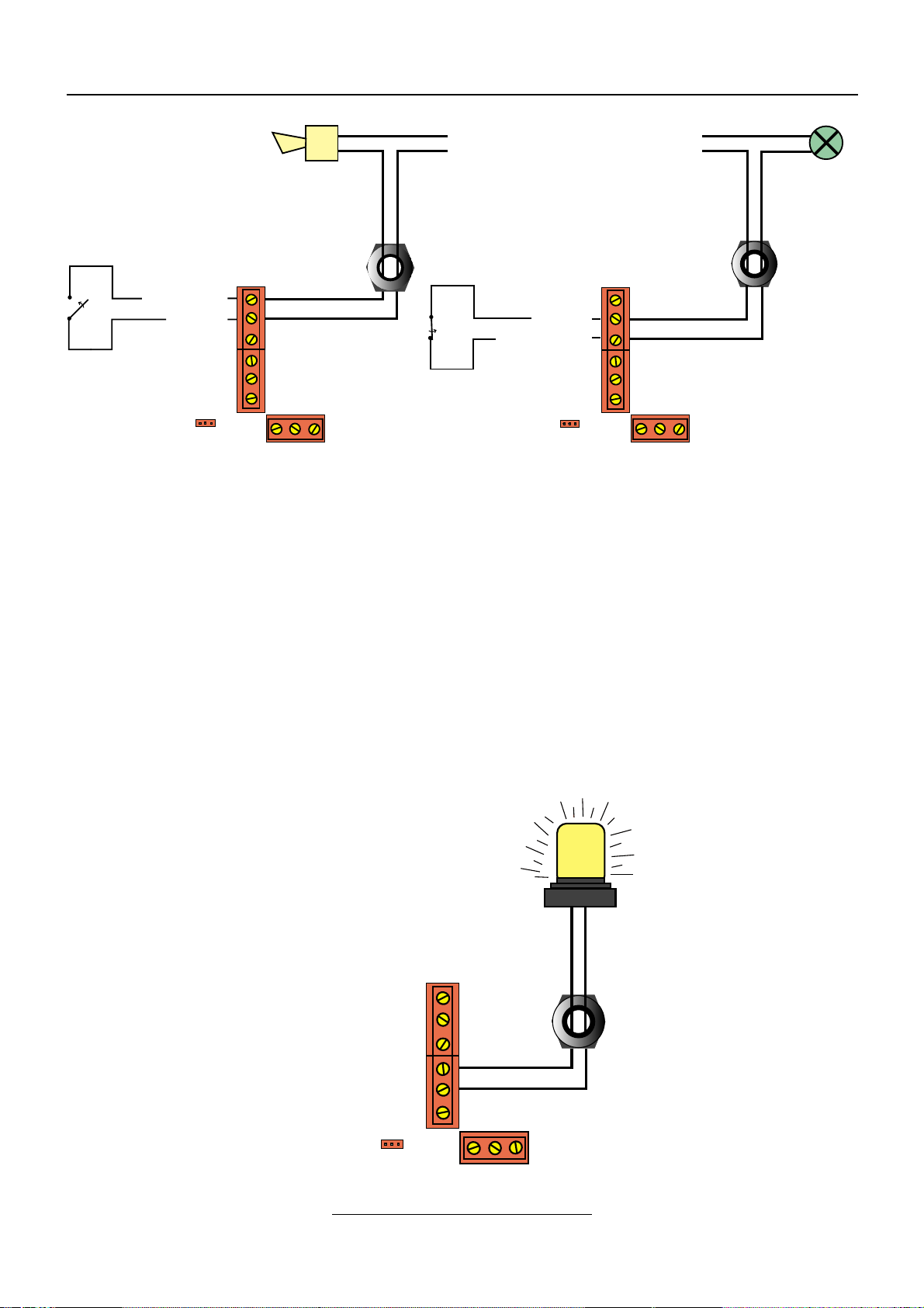
7. High Voltage indicator
When the instrument is generating high voltage the indicator is illuminated. The voltage on the
terminals will be indicated on the voltmeter at all times.
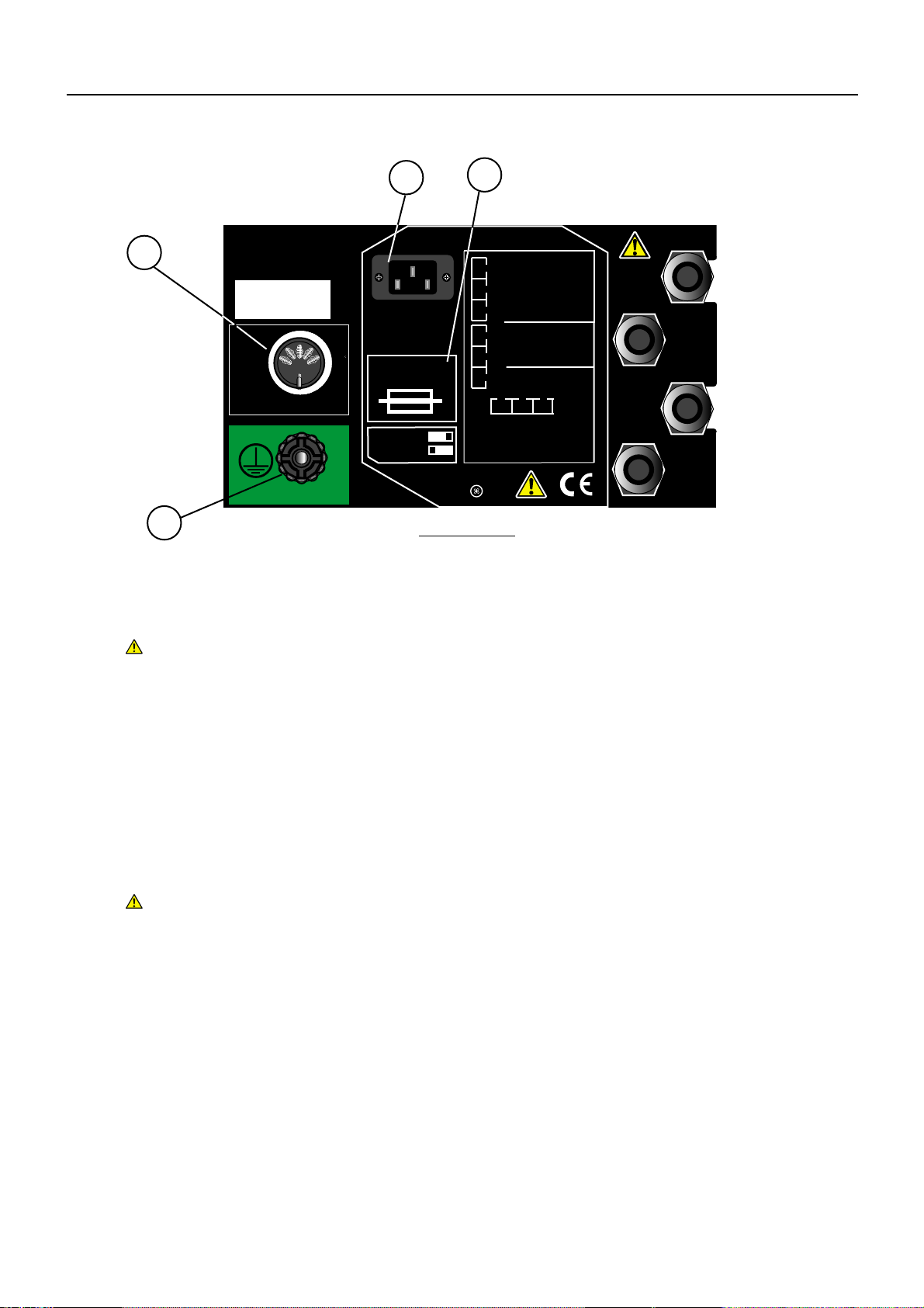
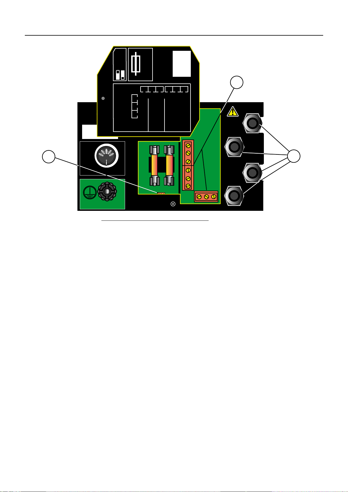
8. High voltage a.c. output receptacle
The HV receptacles used in the instrument are designed to accept a locking plug. To insert the
plug, align the arrows on the plug with the open padlock symbol, push in, and then turn the plug
through 90° to align the arrows with the closed padlock symbol. This will now lock the plug into
the instrument. To remove, turn the plug to align the arrows with the open padlock symbol and
withdraw.
9. High voltage d.c. output receptacle. (MHP2 only)
The H.V. d.c. receptacle locking facility is identical to the a.c. receptacle. The internal H.V.
capacitors are protected by a built-in integral impedance. This effectively causes the d.c.
output voltage to fall, as the test current is drawn. See ‘Specification’.
High Voltage probe
The High Voltage probe is designed to lock into the High voltage receptacle(s) and is fitted with
a hand guard, and a spring loaded electrode cover which retracts as the probe is pressed to the
item being tested. See ‘Accessories’ for replacement probe.
Warning:- The probe must not be used in a damaged or dirty state. Do not touch any
part of the HV probe in front of the guard or the device under test, until
completely discharged.
Warning:- Care must be taken not to touch the probe to any adjacent ungrounded
(unearthed) metalwork such as pipes, window frames etc. as this may
become hazardous live.
10. Low Return terminal
The Low Return lead must be connected to this terminal. The terminal is internally connected to
the instrument ground (earth). The Low Return lead is fitted with a hook connector so that it will
not pull off the terminal. To check this lead, see ‘Before each testing sequence’.Areplacement
low voltage lead is available, see ‘Accessories’.
11. Start button
Controls the high voltage output. Either of two modes of operation can be selected and set using
a moveable link situated behind the rear panel cover:-
i) The latched mode (link to the right) allows the user hands free operation. Operation of the
Stop button, quickly followed by the Start button causes HV generation until the test fails,
or the Stop button is pressed.
ii) The unlatched mode (link to the left) requires the Stop button to be pressed, followed
quickly by the Start button, which must be held in for the entire test. The test can be
stopped at any time by releasing the Start button or by pushing the Stop button. The
instrument will halt the test should the test parameters be exceeded.
12. Stop button
When pushed the stop button:-
✱Stops the test
✱Resets a failure indication.
✱Initiates a start sequence. To avoid inadvertent test voltage application, the test
Start sequence requires the Stop button to be pressed first, followed by pressing the Start button
within 1 second.
Features, Controls and Connections
6

1. Protective Ground (Earth) terminal
For safety, the instruments must be properly earthed. A protective ground (earth) lead must be
correctly connected from the this terminal to a reliable ground (earth) before testing.
Warning:- The IEC power supply cord connection to ground (earth) must notbe
solely relied upon. If the ground (earth) connection of the IEC lead becomes
disconnected, or defective, the metal instrument case could become ‘live’
rising to the dangerously high output voltage of the instrument. A second
ground must be connected to the protective ground terminal on the rear of
the instrument.
2. R/C Remote On /Off receptacle
The optional AVO remote On / Off unit RC1 plugs into this receptacle allowing remote activation
of the unit (see ‘Accessories’).
Warning:- The remote On / Off unit is not a safety interlock and must not be
used as such.
3. IEC Line connector
Provides a means of disconnection from the line supply. To gain access to the line supply fuses,
the Start button mode link, and the customer terminals, the IEC line connector must be removed
from the instrument. The screw holding the cover in position is then removed and the cover can
be swung up out of the way, exposing the interface terminals, Start button mode link, and fuses.
4. Fuse Replacement
The fuses provide protection for the user and instrument. To gain access to the fuses, remove
the IEC mains connector from the instrument. The screw holding the cover in position is then
removed and the cover can be swung up out of the way, exposing the fuses. Replacement fuses
must be of the correct type and rating. See ‘Specification’.
7
RELAY
HV ON
INTER
-LOCK
INTER
-LOCK
R/C
230V
50/60Hz
40VA
2 x T2A HBC
IEC 127
LATCHED
UNLATCHED
N/O
COM
N/C
250V
8A MAX
HV ON
HV ON
P2 - R
P1 - R
P2 - S
P1 - S
INTER
-LOCK
BLUEBELL PA 19422, USA.
DALLAS, TX 75237 - 1017, USA.
AVO International
MADE IN UK.
DOVER CT17 9EN, UK.
100 W
MAX
1
2
1
3
Rear Panel
4
On the rear panel, other features of the instrument can be accessed:-

Features, Controls and Connections
8
RELAY
HV ON
INTER
-LOCK
INTER
-LOCK
R/C
BLUEBELL PA 19422, USA.
DALLAS, TX 75237 - 1017, USA.
AVO International
MADE IN UK.
DOVER CT17 9EN
230V
50/60Hz
40VA
2 x T2A HBC
IEC 127
LATCHED
UNLATCHED
N/O
COM
N/C
250V
8A MAX
HV ON
HV ON
P2 - R
P1 - R
P2 - S
P1 - S
INTER
-LOCK
100 W
MAX
2 x T2A
HBC
IEC 127
5
6
Terminal connections and fuses
5. Start mode link (under cover plate)
To gain access to the Start mode link, remove the IEC mains connector from the instrument. The
screw holding the cover in position is then removed and the cover can be swung up out of the
way, exposing the Start button mode link. The link has two positions; to the left provides the
unlatched mode, to the right provides the latched mode. Gently pull to remove the link from the
terminals, and re-position as required.
6. Interface and Interlock terminals (under cover plate)
To gain access to the interface terminals, remove the IEC mains connector from the instrument.
The screw holding the cover in position is then removed and the cover can be swung up out of
the way, exposing the interface terminals. The terminals are not suitable for solid core wires.
Multi-stranded conductors, 22-16 AWG (1mm2- 1,5 mm2) should be used. The use of wire
ferrules is recommended to eliminate stray strands of wire; recommended insulation strip length
is 8 mm. The terminal screws should be tightened securely. On completion, the cover plate
should be swung back into position and secured by replacing and tightening the cover plate
retaining screw.
Terminal connections and fuses
The interface terminals are in three groups:-
i) Relay Terminals
The top three terminals are for applications that require an external test status indication.
‘Test Failed’ and ‘Test OK’ can be signalled. The maximum current that can be switched
is 8 Amp at 250 Volts.
7

When the ‘Failed’ condition is active, the Common terminal is shorted to the Normally Open
(N/O) terminal.
When the ‘Failed’ condition is active the Common terminal and the Normally Closed (N/C)
terminal are open circuited by the instrument.
To gain access to the relay terminals, the IEC line connector must be removed from the
instrument. The screw holding the cover in position is then removed and the cover can be swung
up out of the way, exposing the interface terminals.
ii) HV On Terminals
Some regulations call for various signalling lamps to indicate hazardous and
potential Risk situations. The terminals shown allow for the connection of a Line powered
‘High Voltage On’ indicator or beacon. See ‘Accessories’ for Warning beacon. A
maximum current of 1⁄2Amp can be drawn from these terminals.
HV ‘On’ terminal connections
9
Normal Open
Common
Phase
Neutral
Alarm
Sounder
Common
Phase
Neutral
Normal Closed
Indicator
Lamp
Cable
gland Cable
gland
Start mode link Start mode link
HV On
HV On
Cable gland
Start mode link
Line voltage
at up to Amp
1/2

iii) HV Interlock Terminals
The bottom four terminals enable the HV supply to be safety interlocked. The instrument is
supplied without the interlock terminals connected. The HV interlock terminals must be
connected before the instrument will generate High Voltage. The Users HV safety interlock
system must conform to National and Local safety codes and be designed in such a way that
any contact with live parts is prevented. This is normally achieved by a solid barrier that must be
removed before access can be obtained to the hazardous area. The action of removing the
barrier forces the interlock switches to the open position thus interrupting the supply voltage for
the HV generation circuit. The interlock connections operate at Line (mains) voltage. All wiring
connected to these terminals must rated for Line (mains) use and capable of carrying a current
of 3 amps.
Interlock connection example
7. Cable entry glands
When wiring the safety interlocks, the wires to the terminals must pass through the cable entry
glands and then be connected to the appropriate terminals. Cables of 1⁄8” to 1⁄4” (3 mm to
6.5 mm) outer insulation diameter can be used. The glands must be sufficiently tightened, after
wiring, so that flexing the external cord does not cause any movement of the wires inside the
panel. On completion, the cover plate should be swung back into position and secured by
replacing and tightening the cover plate retaining screw.
Features, Controls and Connections
10
P2 - R
Guard Op
Optional 'Ready to
Test' Indicator
P1 - S
P1 - R
P2 - S
Cable gland
Cable gland
Line voltage
on terminals
Start mode link
Guard in
Open
Position
Interlock
switch
(user supplied)

Testing Precautions
✱High voltage testing is potentially lethal. Care must be taken at all times to ensure that risks
to safety are eliminated.
✱The instruments must only be used by suitably trained and competent persons.
✱The instrument User is responsible for their own safety and that of others who may come
into contact with dangerous voltages as a result of a test.
✱For safety, the instrument must be double grounded (earthed) to known good ground
(earth) point. Firstly by the line powercord, and secondly from the rear protective ground
(earth) terminal. During the installation process both ground (earth) connections should be
checked to prove their integrity. See ‘Before each testing sequence’.
✱Before operating the Line On / Off switch, ensure that the voltage control is set to minimum.
If this is not done a voltage transient could occur at the output terminal which could cause
damage to the item under test or endanger the user.
✱When making connections to the instrument, and to the device to be tested, ensure the
instrument is in a safe condition, with all safety interlocks open.
✱If any part of the instrument is damaged, it should not be used, but returned to the
manufacturer or an approved organization for repair.
Charged Circuit Discharge
For d.c. tests and when testing capacitors or equipment containing capacitors, extra care must
be taken by the User to ensure that the item under test is fully discharged before handling. The
instrument provides a discharge path which will discharge 0,5 µF in 10 seconds. Even a small
deflection of the voltmeter may represent a hazardous voltage.
Warning:- Care must be taken to prevent capacitive circuits becoming disconnected
during a test, leaving the circuit in a charged state. Automatic discharge must not be
relied upon as an alternative to normal safe working practice.
Dielectric Absorption
Some capacitive items exhibit an effect called Dielectric Absorption. The dielectric can
absorb charge during the test.After the item is discharged, the absorbed charge is released
back onto the capacitive ‘plates’effectively raising the voltage of the item, possibly to
dangerous levels. Safe working practice dictates that tested items should be firmly
shorted out with a shorting link, after discharge, until required for use.
✱The instrument is supplied with a 3 wire power cord. The instrument must be used with a
grounded (earthed) supply, and all 3 wires must be connected.
The colour code of the cord is :- U.S.A. U.K. / International
Ground (Earth) Green Yellow/Green
Neutral White Blue
Line (Phase) Black Brown
If using a fused plug, a 3 Amp fuse to BS1362 should be fitted.
Operation
11

Before each testing sequence:-
1. Decide upon the Start mode required, and connect the Start mode link in the appropriate
position.
2. Check the condition of the HV probe and test lead (or LV probe) to ensure that they are
in good order, clean, with no broken or damaged insulation. A daily Continuity test is
recommended. To check the HV probe and test lead (or LV probe):-
i) Plug the HV probe in the a.c. HV receptacle.
ii) Ensure that the Low Return lead (or LV probe) is firmly secured to the Low return
terminal.
iii) Set the voltage control to minimum.
iv) Set the trip mode to TRIP and set the trip current limit to 0.3 mA.
v) Switch the instrument on. The switch illuminates.
vi) Short the HV probe and the end of the Low Return lead (or LV probe) together.
vii) Start the instrument and slowly increase the voltage.
3. The instrument should trip before the voltmeter pointer moves. If the pointer moves, the
test leads are suspect, and must be fully, and properly inspected.
4. Ensure that the voltage control is set to minimum before operating the line power switch.
If this is not done a voltage transient could occur at the output terminal which could cause
damage to the item under test or endanger the user.
5. Check that all interlocks are fully operational.
Carrying out a test
1. Set the required:- i) Test mode (Breakdown - Trip / Breakdown - Trip)
ii) Trip level (0.3 mA to 10 mA)
2. Connect the HV probe and the Low Return lead to appropriate points of the device under
test. For safety it is advisable to connect the HV to the least accessible part of the item
under test.
3. Close all interlocks.
4. Switch the instrument on. The switch illuminates.
5. Push the Stop button, followed quickly by the Start button. (Depending on the selected
Operation
12
High Voltage testing is hazardous. Safety Warnings and Testing
Precautions must be read and understood. They must be observed
during use.
High Voltage testing is hazardous. Safety Warnings and Testing
Precautions must be read and understood. They must be observed
during use.
The condition of the HV probe and test lead is critical to overall
safety. A faulty or damaged HV probe or test lead must not be
used under any circumstances.

mode the Start button is released, or held for the duration of the test).
6. Once the HV circuit is energised, adjust the voltage to the test level required.
Note:- It is advisable to slowly increase the test voltage from a low value, giving the insulation
within the device under test, time to react to the stress. This will also reduce false tripping due to
switching On at the required test level. This is especially true for d.c. tests.
7. If the test fails, the failed indication will light and the buzzer will sound. Repeat the test to
confirm the failure.
8. Press the Stop button to switch the High Voltage off and to reset the failure indication.
9. To stop the test after the correct time press, the Stop button (or release the Start button).
On completion, open all safety interlocks. Switch the Withstand tester Off.
Note:- When performing an a.c. test, capacitance of the test leads can cause a small leakage
current. Typically, this is in the order of 20 µA per metre, for each 1000 V of test voltage. This
effect is normal, but may cause the instrument to trip at a lower level of leakage than expected.
This effect is most noticeable at the lower trip ranges. It is therefore important to consider this
effect before extending the test leads in any way.
Switched Low Voltage probe LP2
In conjunction with the HV probe provided, the optional LV probe allows remote activation of the
Withstand tester enabling fast, safe probing of the item under test.
1. Refer to ‘Carrying out a test’.
2. Connect the probe DIN plug to the R/C socket, and firmly secure the hook terminal to the
Low return terminal. Connect the HV probe to the appropriate HV receptacle.
3. Switch the Withstand tester on and set the Test mode, Trip level, and Voltage as required.
Check that all safety interlocks are closed.
4. Firmly hold both probes to the item under test. For safety it is advisable to hold the HV
probe to the least accessible part of the item under test.
5. Squeeze the LV probe switch to start the test.
6. Release the LV probe switch to stop the test.
7. As required, move the probe around the item under test, operating the probe switch as
appropriate.
8. If the test fails, the ‘Fail’indicator will light, and the buzzer will sound.
9. To reset the Withstand tester ‘Fail’indicator, disengage the probes, and briefly squeeze
the LV probe switch. Repeat the test to confirm a test ‘Fail’.
On completion, open all safety interlocks. Switch the Withstand tester Off.
13
High Voltage testing is hazardous. Safety Warnings and Testing
Precautions must be read and understood. They must be observed
during use.

120 kΩResistance Box
This optional accessory is used to check that the instrument will operate and indicate correctly,
when an item under test has significant insulation leakage current.
1. Refer to ‘Carrying out a test’.
2. Firmly connect the supplied lead from the Resistance Box to the instrument Low return
terminal. Connect the HV probe to the appropriate HV receptacle.
3. Switch the Withstand tester on and set the Test mode, Trip level, and Voltage as
required. Check that all safety interlocks are closed.
4. Firmly hold the instrument HV probe to the Resistance Box test point stud.
The HV probe tip, and the resistance box must not be touched during the operation.
5. Start the instrument.
6. The instrument should instantly indicate ‘Fail’, and sound the buzzer.
7. Press the Stop push to reset the Withstand tester. Repeat the test to confirm a test ’Fail’.
On completion, open all safety interlocks. Switch the Withstand tester Off.
Note:- If the instrument does not operate within 5 seconds, Stop the Test (to prevent excess
heat damage to the Resistance Box).
Operation
14
High Voltage testing is hazardous. Safety Warnings and Testing
Precautions must be read and understood. They must be observed
during use.

MHP1 MHP2
Test Voltage: 0 - 3 kV a.c. 0 - 3 kV a.c.
0 - 4 kV d.c.
d.c. ripple content: <150 V d.c. pk - pk at 1 mA
Display: Analogue movement - Sifam 29W
Display Accuracy: ± 2.5% of full scale deflection
Current Trip: Peak or d.c. 0.3 mA, 0.5 mA, 1.0 mA, 2.0 mA, 3.5 mA, 5.0 mA,
10.0 mA
Current trip accuracy: ± 10% of indicated value - 0.3 mA and 0.5 mA ranges
± 5% of indicated value - All other ranges
Typical Cap. leakage: 25 µA per 1000 V test voltage - Standard probe (5310-406)
Safety: Meets the requirements of IEC 1010-1 (1995) EN61010-(1995)
Fuses: 2 x T2A HBC 11⁄4”x 1⁄4”(32 mm x 6,5 mm)
Line power cord fused plug (when applicable): 3 Amp fuse to BS
1362
EMC: Meets EN50081-1, EN50082-1 (1992). Meets EN61326-1 in the
following categories:- IEC10004-2 Cat A; IEC10004-3 Cat A;
IEC10004-4 Cat A; IEC10004-5 Cat C; IEC10004-11 Cat A.
Temperature:
Operating: 32˚F to 104˚F (0˚C to 40˚C)
Storage: 4˚F to 140˚F (-20˚C to 60˚C)
Humidity:
Operation: 80% RH at 104˚F (40˚C)
Note:- After storage in high humidity, or moving from a cold to warm environment, allow the
instrument to sit for at least 3 hours before use.
Dimensions: 11”x 111⁄2”x 43⁄4”(257 mm x 280 mm x 110 mm)
Weight: 17. 6 lb (8 kg)
Specification
15
Typical d.c. Loading
115 V. instrument 230V. instrument

The instrument circuit contains static sensitive devices, and care must be taken in handling the
printed circuit board. If the protection of an instrument has been impaired it should not be
used, and be sent for repair by suitably trained and qualified personnel. The protection is likely
to be impaired if, for example, the instrument shows visible damage, fails to perform the
intended measurements, has been subjected to prolonged storage under unfavourable
conditions, or has been exposed to severe transport stresses.
New Instruments are Guaranteed for 1 Year from the Date of Purchase by the User.
Note:- Any unauthorized prior repair or adjustment will automatically invalidate the
Warranty.
Instrument Repair and Spare Parts
For service requirements for MEGGER®Instruments contact :-
AVO INTERNATIONAL or AVO INTERNATIONAL or MEGGER SARL
Archcliffe Road Valley Forge Corporate Center 29 Allée de Villemomble
Dover 2621 Van Buren Avenue 93340, Le Raincy
Kent, CT17 9EN. Norristown, PA 19403 Paris
England U.S.A. France
Tel: +44 (0) 1304 502243 Tel: +1 (610) 676-8579 Tel: +33 (1) 43.02.37.54
Fax: +44 (0) 1304 207342 Fax: +1 (610) 676-8625 Fax: +33 (1) 43.02.16.24
or an approved repair company.
Approved Repair Companies
A number of independent instrument repair companies have been approved for repair work on
most MEGGER®instruments, using genuine MEGGER®spare parts. Consult the Appointed
Distributor / Agent regarding spare parts, repair facilities and advice on the best course of action
to take.
Returning Instrument for Repair
If returning an instrument to the manufacturer for repair, it should be sent freight pre -paid to the
appropriate address.Acopy of the Invoice and of the packing note should be sent simultaneously
by airmail to expedite clearance through Customs. A repair estimate showing freight return and
other charges will be submitted to the sender, if required, before work on the instrument
commences.
Repair and Warranty
16

Cleaning: Wipe disconnected instrument with a clean cloth dampened with
soapy water or Isopropyl Alcohol (IPA).
Supplied Part Number
User Guide 6172-314
Mains Power cord
Low Return lead 6220-309
4 kV High Voltage Probe
Optional
Retractable type High Voltage Probe HP1 6420-061
Warning Beacon 6121-446
Remote On / Off switch unit RC1 6220-641
120 kΩResistance Box 6121-447
Switched Low Voltage probe LP2 6121-456
Accessories
17

AVO INTERNATIONAL
Archcliffe Road
Dover, Kent
CT17 9EN Tel: +44 (0) 1304 502100
England. Fax: +44 (0) 1304 207342
4651 S. Westmoreland Road
Dallas Tel: +1 (800) 723-2861 (U.S.A. only)
TX 75237-1017 Tel: +1 (214) 330-3203 (International)
U.S.A. Fax: +1 (214) 337-3038
PO Box 9007
Valley Forge
PA 19484-9007 Tel: +1 (610) 676-8569
U.S.A. Fax: +1 (610) 676-8610
MEGGER SARL
29 Allée de Villemomble
93340, Le Raincy
Paris Tel: +33 (1) 43.02.37.54
France Fax: +33 (1) 43.02.16.24
This instrument is manufactured in the United Kingdom. The Company reserves the right to change the specification or design without prior notice.
MEGGER and AVO are registered Trade Marks of AVO INTERNATIONAL LIMITED. Copyright©AVO INTERNATIONAL LIMITED.
Part Number 6172-314 - Edition 5 - Printed in England - 07FF LEET
This manual suits for next models
1
Table of contents
Other Megger Test Equipment manuals

Megger
Megger TPT320 User manual

Megger
Megger BITE5 User manual

Megger
Megger BM220 Series User manual

Megger
Megger MTB7671 User manual

Megger
Megger MIT417 User manual

Megger
Megger 128311841 User manual

Megger
Megger SVERKER 750 User manual

Megger
Megger MIT200 Series User manual

Megger
Megger PCITS600/2 User manual

Megger
Megger MTR105 User manual

Megger
Megger BM121 User manual

Megger
Megger EVCC 300 User manual

Megger
Megger DET5/4R User manual

Megger
Megger SG32-1500M User manual

Megger
Megger BM11D User manual

Megger
Megger BALTO Modular User manual

Megger
Megger MFT1741 User manual

Megger
Megger Surgeflex 12 User manual

Megger
Megger BITE2 User manual

Megger
Megger MVCT User manual