manuals.online logo
Brands
  1. Home
  2. •
  3. Brands
  4. •
  5. Metal Work
  6. •
  7. Control Unit
  8. •
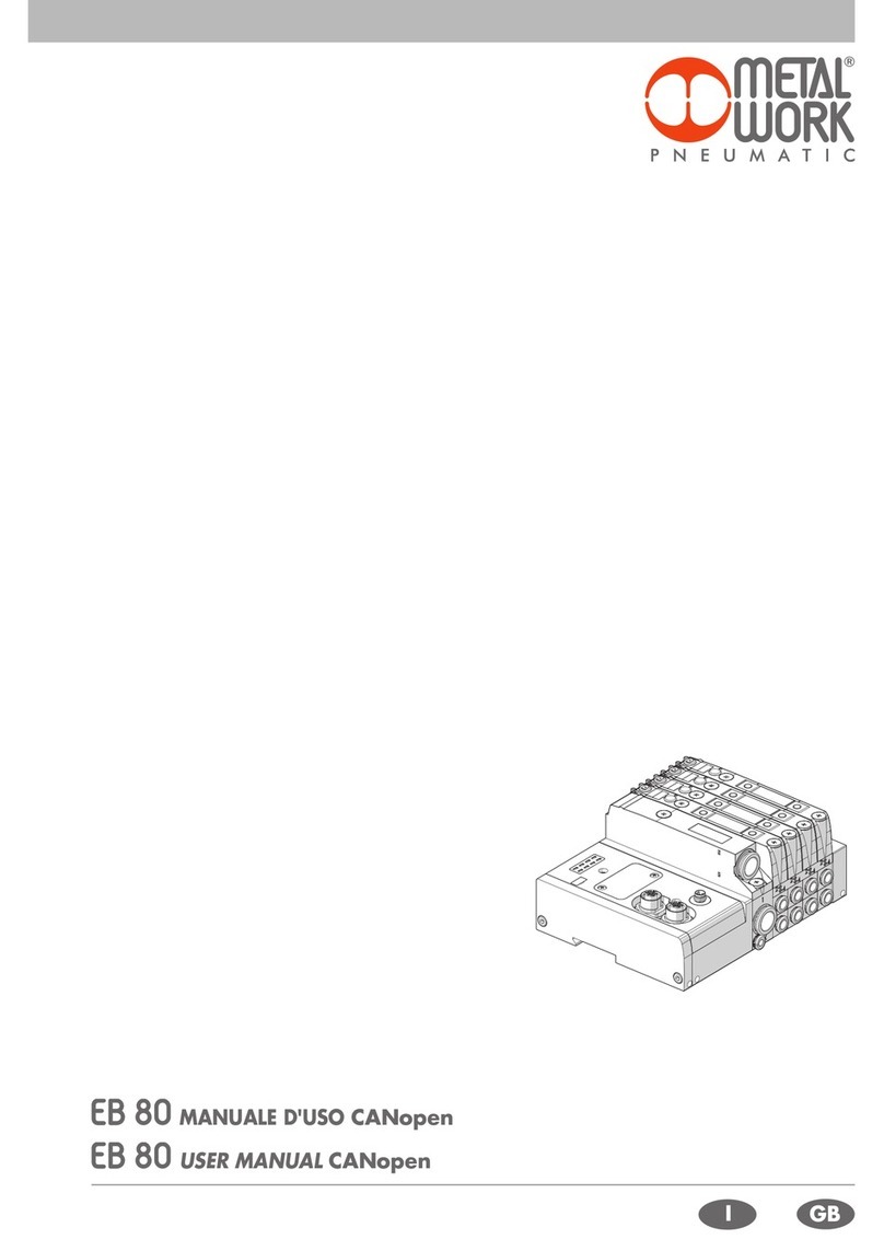
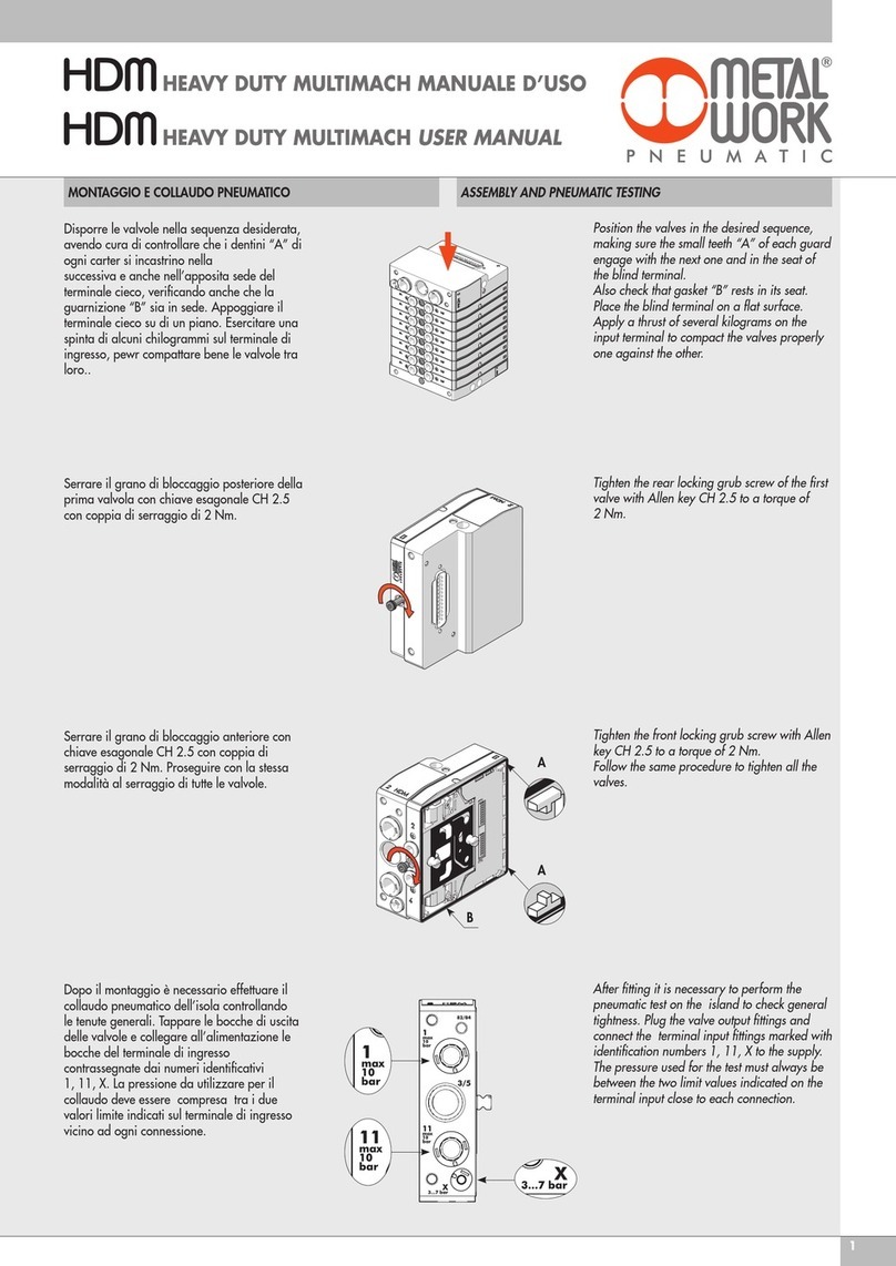
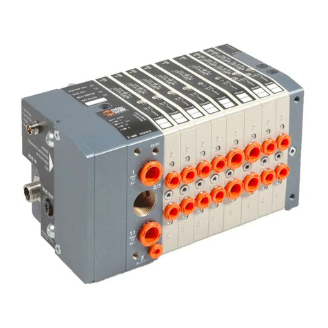
  9. Metal Work EB 80 User manual

Metal Work EB 80 User manual

IGB
ISTRUZIONI MONTAGGIO ASSEMBLY INSTRUCTIONS
2
Svitare le due viti con cacciavite a croce PH1.
Sfilare la valvola.
Dopo aver verificato il corretto posizionamento delle guarnizioni inserire
la nuova valvola.
Avvitare le due viti con cacciavite a croce PH1, applicando una coppia
di 1.1 ÷ 1.3 Nm. Serrare prima la vita A e poi la B.
A
B
SOSTITUZIONE VALVOLE REPLACING THE VALVE
Unscrew the two screws with a screwdriver PH1 cross-slotted.
Remove the valve.
Check that the seals are positioned properly and insert the new valve.
Tighten the two screws with a screwdriver PH1 cross-slotted at a torque
of 1.1 - 1.3 Nm. First tighten screw A and then screw B.
3
MONTAGGIO ISOLA INSTALLING THE ISLAND
Avvitare a mano i tre tiranti adell’alimentazione pneumatica alla
connessione elettrica b.Hand tighten the three tie rods aof the compressed air
supply system for connection to the power supply b.
Inserire l’alimentazione pneumatica ③, facendo attenzione che la scheda
elettronica entri nelle guide presenti sull’alimentazione pneumatica.
NON FORZARE.
Avvitare a mano i tre tiranti d ed inserire la base e. Prestare attenzione
ad inserire correttamente la scheda elettronica. Qualora si avvertissero
impuntamenti muovere delicatamente la scheda per favorirne l’inserimento
oppure spingere delicatamente la scheda di testa verso il basso aiutandosi
con un cacciavite. Ripetere l’operazione per tutte le basi.
Activate the compressed air supply ③, making sure the electronic board
fits into the slots provide. DO NOT FORCE!
Hand tighten the three tie rods d and insert the base e. Make sure the
electronic board is fitted properly. Should there be any hard spots, gently
move the board to facilitate its insertion or gently push the end plate
board downwards using a screwdriver. Repeat the operation for all the
bases.



4
Appoggiare l’isola su una superficie piana, inserire il terminale cieco 
e serrare le tre viti con una coppia di 2 Nm. Nelle versioni con scheda
elettronica (C2-C3) fare attenzione all’allineamento delle schede.
NON FORZARE.
Place the island on a flat surface, insert the blind end plate and tighten
the three screws  at a torque of 2 Nm. In the versions with electronic
board (C2-C3), make sure the boards are properly aligned.
DO NOT FORCE.
Dopo aver verificato il corretto posizionamento delle guarnizioni,
montare le valvole e avvitare le viti con cacciavite a croce PH1, con una
coppia di 1.1 ÷ 1.3 Nm. Serrare prima la vita A e poi la B.
After checking that the seals are positioned properly, install the valves
and tighten the screws with a cross screwdriver PH1 at a torque of
1.1 - 1.3 Nm. First tighten screw A and then screw B.
Sull’ultima base svitare i tre grani M4 f.
Serrare i tre tiranti g con chiave esagonale da 4 mm applicando una
coppia di 2 Nm.
NB: per un allineamento ottimale delle schede è consigliabile
assemblare le basi SENZA la valvole montate.
Unscrew the three M4 grub screws on the end base f.
Tighten the three tie rods g using a 4 mm socket wrench at a torque of
2 Nm.
N.B. For the optimal alignment of the boards, it is advisable to install
the bases WITHOUT the valves assembled.
A
B
Lubrificare il filetto
lubricate the thread

5
MONTAGGIO I/O ASSEMBLING THE I/O MODULE
Svitare le viti M4 e togliere la piastra di chiusura della connessione
elettrica. Unscrew the M4 screws on the power connection end plate and
remove the plate .
Avvitare i due tiranti del modulo I/O e serrare con coppia di 2 Nm.
Inserire il modulo I/O facendo attenzione all’allineamento della
scheda elettronica. NON FORZARE
Tighten the two tie rods of the I/O module at a torque of 2 Nm.
Rimontare la piastra facendo attenzione all’allineamento della
scheda elettronica. NON FORZARE. Serrare le viti M4  con una
coppia di 2 Nm.
Refit the plate , making sure the electronic board is aligned properly.
DO NOT FORCE. Tighten the M4 screws at a toque of 2 Nm.
Insert the I/O module , making sure the electronic board is aligned
properly. DO NOT FORCE.
Lubrificare il filetto
Lubricate the thread
6
SOSTITUZIONE RACCORDI REPLACING THE FITTINGS
Togliere le clips aiutandosi con un cacciavite. Use a scewdriver to remove the clips.
Sfilare i raccordi.
Inserire i nuovi raccordi fino in battutta.
Remove the fittings.
Inserire nuovamente le clip fino in battutta. Refit the clips and tighten until they go.
Insert the new ones until they go.
7
MONTAGGIO IN BARRA DIN FIXING THE ISLAND TO A DIN BAR
Agganciare l' isola alla barra DIN dal lato predisposto. Fix the island to the designated side of the DIN bar.
Serrare i grani di fissaggio con uan coppia di 0.5 Nm. Tighten the grub screws at a torque of 0.5 Nm.
8www.metalwork.eu
EQZZZZ006 ITA_GB - IM01 - 02/2019
NOTE NOTES

Other manuals for EB 80

9

Other Metal Work Control Unit manuals

Metal Work Multimach User manual

Metal Work

Metal Work Multimach User manual

Metal Work EB 80 User manual

Metal Work

Metal Work EB 80 User manual

Metal Work HDM series User manual

Metal Work

Metal Work HDM series User manual

Metal Work EB 80 User manual

Metal Work

Metal Work EB 80 User manual

Metal Work EB 80 User manual

Metal Work

Metal Work EB 80 User manual

Metal Work EB 80 User manual

Metal Work

Metal Work EB 80 User manual

Metal Work HDM User manual

Metal Work

Metal Work HDM User manual

Metal Work EB 80 User manual

Metal Work

Metal Work EB 80 User manual

Metal Work HDM User manual

Metal Work

Metal Work HDM User manual

Metal Work EB 80 User manual

Metal Work

Metal Work EB 80 User manual

Metal Work HDM User manual

Metal Work

Metal Work HDM User manual

Metal Work HDM series User manual

Metal Work

Metal Work HDM series User manual

Metal Work Safe Air 70 series User manual

Metal Work

Metal Work Safe Air 70 series User manual

Metal Work Safe Air 70 series User manual

Metal Work

Metal Work Safe Air 70 series User manual

Metal Work EB 80 User manual

Metal Work

Metal Work EB 80 User manual

Popular Control Unit manuals by other brands

Festo MS4-A-IPM-80 Assembly instructions

Festo

Festo MS4-A-IPM-80 Assembly instructions

FrSky R9M 2019 LBT instruction manual

FrSky

FrSky R9M 2019 LBT instruction manual

Jolly Mec Control Display user manual

Jolly Mec

Jolly Mec Control Display user manual

Tektronix TM 5003 instruction manual

Tektronix

Tektronix TM 5003 instruction manual

Honeywell BA295D-3WH installation instructions

Honeywell

Honeywell BA295D-3WH installation instructions

Equinox Systems PPM3 Reference manual

Equinox Systems

Equinox Systems PPM3 Reference manual

Siemens Maxum II PD PA AP Service manual

Siemens

Siemens Maxum II PD PA AP Service manual

Jetter JXM-IO-E32 user manual

Jetter

Jetter JXM-IO-E32 user manual

Somati system FSTronic IRC-FI manual

Somati system

Somati system FSTronic IRC-FI manual

Flowserve T4E-1 Technical manual

Flowserve

Flowserve T4E-1 Technical manual

Larkin AFC-DCV Installation, operation and maintenance instructions

Larkin

Larkin AFC-DCV Installation, operation and maintenance instructions

Tibbo EM1000 Programmable Hardware Manual

Tibbo

Tibbo EM1000 Programmable Hardware Manual

Milltronics smartlinx instruction manual

Milltronics

Milltronics smartlinx instruction manual

Polycom SpectraLink 6300 MCU install guide

Polycom

Polycom SpectraLink 6300 MCU install guide

ELECRAFT KAT2 Notes

ELECRAFT

ELECRAFT KAT2 Notes

NPI PDES-01DM Operating instructions and system description

NPI

NPI PDES-01DM Operating instructions and system description

STC 3V110-410 Series quick start guide

STC

STC 3V110-410 Series quick start guide

Honeywell hmr3000 TruePoint user guide

Honeywell

Honeywell hmr3000 TruePoint user guide

manuals.online logo
manuals.online logoBrands
  • About & Mission
  • Contact us
  • Privacy Policy
  • Terms and Conditions

Copyright 2025 Manuals.Online. All Rights Reserved.