2
1. SYSTEM SPECIFICATIONS
Ambient Operating Temperature 10 - 40°C
Maximum Enclosure Temperature 55°C
Input Line Voltage 100 - 240 VAC, grounded circuit
Input Line Frequency 50/60 Hz
Power Consumption 125W
Output Power (Max.) 80 Watts max. Per channel at 22°C ambient temperature
Output Frequency 13.56 MHz
Power Cord 3-Wire 183cm (18/3”) SJT
Dimensions w x d x h 12.1 cm (4.8”) x 13.0cm (5.1”) x 23.5cm (9.3”)
Certification / Marking cTUVus, CE
Surface Resistivity 105- 109Ω/in
Tip-to-Ground Potential <2mV
Tip-to-Ground Resistance <2 ohms
Idle Temperature Stability ± 1.1°C in still air
Hand-piece Cable Length L=122cm (48”), burn proof, ESD safe
Hand-piece Connector F connector
Workstand Dimensions w x d x h 8.6 cm (3.4”) x 19.1 cm (7.5”) x 8.3 cm (3.3”)
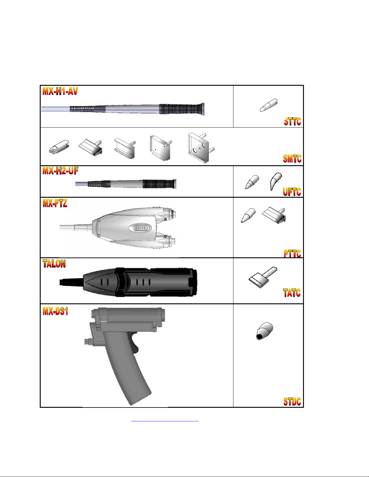
2. SYSTEM DESIGN AND TECHNOLOGY OVERVIEW
The MX-5200 Series is a precision, high-power soldering system with dual switchable ports. It is the
newest design of the market leading Metcal soldering systems. It adds ergonomic hand-pieces, a built
in power meter, 80 watts of power per channel or 40 watts simultaneous, and includes SmartHeat®
Technology for quick response and precise control.
a.SMARTHEAT®TECHNOLOGY
No Calibration Required
Each cartridge is equipped with a self-regulating heater which ‘senses’ its own temperature and
closely maintains its pre-set idle temperature for the life of the heater-tip; all controlled by OK
International’s proprietary SmartHeat®Technology. The tip temperature is determined by the inherent
metallurgical properties of the heater; no external adjustment or equipment is required. This
eliminates spikes and transients associated with electrically switched elements found in conventional
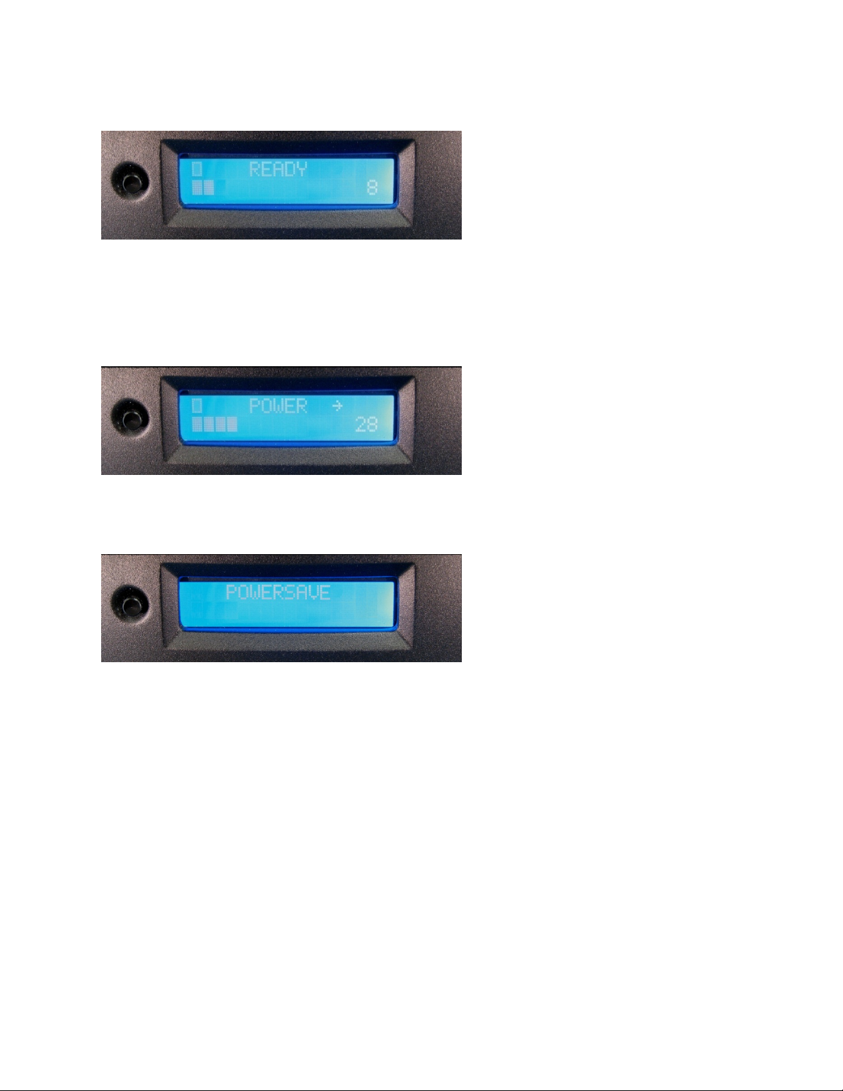
soldering irons. The integrated power indication meter actively monitors power delivered to the tip as
it varies in direct response to the thermal load. The power indication meter requires no calibration,
because it is monitoring an active feedback loop. Please feel free to contact your OK International
representative with any questions.
Those companies or individuals requiring periodic verification of system performance may do so in
the following ways:
Measure the performance of the system in ‘time required to solder a defined number of loads’, or
Observe start up and idle power with the integrated Power Indication Meter, or
Measure tip idle temperature as it equates to this performance.