METER EM60 Series User manual

EM60

i
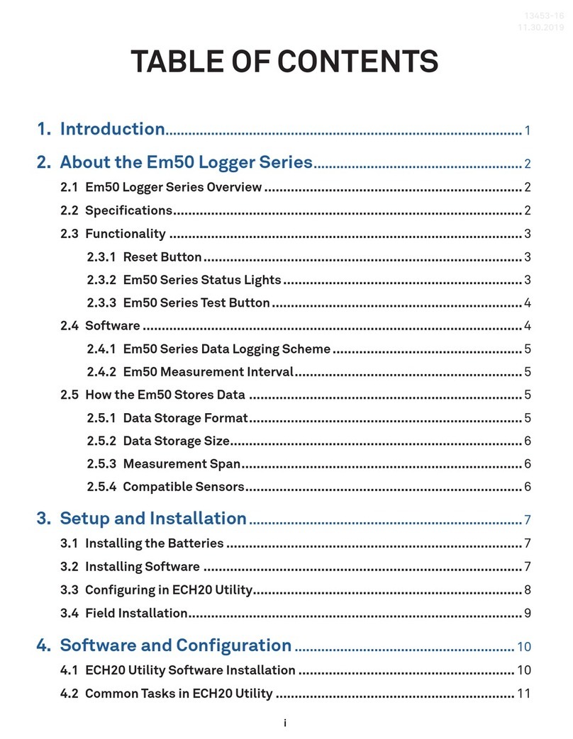
TABLE OF CONTENTS
1. Introduction.............................................................................................. 1
2. Operation ...................................................................................................2
2.1 Installation ................................................................................................2
2.2 Configuration.............................................................................................4
2.3 Cellular Communication Test (EM60G Only)...............................................9
2.4 Instantaneous Sensor Measurements Scan............................................. 10
2.5 Data Download ........................................................................................ 10
2.6 Data Deletion........................................................................................... 11
3. System....................................................................................................... 12
3.1 Specifications.......................................................................................... 12
3.2 EM60 Hardware Components .................................................................. 13
3.2.1 Sensor Interface ............................................................................ 14
3.2.2 Sensor Measurement Interval........................................................ 15
3.2.3 Test Button .................................................................................... 15
3.2.4 Status Lights ................................................................................. 16
3.2.5 Batteries ....................................................................................... 16
3.2.6 GPS Receiver.................................................................................. 17
3.2.7 Timekeeping .................................................................................. 17
3.2.8 Data Storage .................................................................................. 18
3.2.9 Cellular Communications (EM60G Only) ........................................ 18
4. ZENTRA Software................................................................................ 19
4.1 ZENTRA Utility ........................................................................................ 19
4.1.1 Button Toolbar ............................................................................... 20
4.1.2 Data Logger Identification Area ..................................................... 20
18206-02
8.9.2019

ii
4.1.3 Active Sensors and Measurements Area........................................ 21
4.1.4 Status Bar...................................................................................... 21
4.1.5 Menu Bar........................................................................................ 21
4.1.6 Manage Settings Dialog ................................................................. 27
4.2 ZENTRA Cloud (EM60G Only) ................................................................... 31
5. Service....................................................................................................... 33
5.1 Maintenance............................................................................................ 33
5.2 Troubleshooting....................................................................................... 34
5.3 Customer Support.................................................................................... 36
5.4 Terms and Conditions .............................................................................. 36
Appendix A. Compliance Certifications....................................... 37
A.1 USA.......................................................................................................... 37
A.2 Canada .................................................................................................... 38
A.3 European Union ....................................................................................... 38
A.4 Japan....................................................................................................... 39
Index ................................................................................................................. 40


1
EM60
1. INTRODUCTION
Thank you for choosing EM60 series data loggers from METER Group.
The EM60 series loggers (EM60 and EM60G) are part of the ZENTRA System, a
collection of data loggers, software, and compatible sensors to measure soil moisture
and other environmental parameters accurately and cost effectively. Please refer to
EM60 specifications at metergroup.com/em60-support for an up-to-date list of supported
sensors.
The EM60 is a self-contained, plug-and-play data logger for field research and commercial
agriculture. It is housed in a weather-resistant enclosure, making it suitable for long-term
outdoor operation. The logger also includes built-in circuitry to charge nickel-metal hydride
(NiMH) batteries using energy from an integrated solar panel.
The EM60 series includes two models:
• EM60 is a manual-download logger.
• EM60G is a remote-download logger that communicates through a cellular module to
transmit data over the internet.
Throughout this manual, references to EM60 apply to both the EM60 and EM60G versions of
the logger unless otherwise specified.
Verify all instrument components are included and appear in good condition:
• EM60 series logger with five installed rechargeable NiMH batteries
• Micro-USB communications cable
• Zip ties for mounting the logger
• USB drive containing ZENTRA Utility software installer
• Antenna (EM60G)
• Device subscription card (EM60G)

2
OPERATION
2. OPERATION
This section explains the basic workflow of logger installation, logger configuration, and
data download. Please read all instructions before operating the EM60 to ensure it performs
to its full potential. Consider testing the EM60 and sensors in a lab or office prior to field
installation to verify the correct operation of the system.
The EM60 can serve as a data collection station for as many as six sensors. It is designed
to be a plug-and-play setup with all METER sensors, including the ECH2O water content
sensors, ATMOS weather sensors, and TEROS soil moisture sensors. Please refer to the
individual sensor manuals for sensor installation instructions.
2.1 INSTALLATION
Follow the steps listed in Table 1 to set up the EM60 and start collecting data.
Table 1 Installation
Tools Needed Microsoft®Windows®or Apple®Mac®computer
Mounting post (or similar)
Preparation
Install ZENTRA Utility
Use the included USB drive to install ZENTRA Utility:
• On a Windows computer, open the My Computer window, select the USB drive,
and double click on ZENTRA Utility PC Installer.exe.
• On a MacOS computer, using Finder®, select the USB drive, and double click
on ZENTRA Utility Mac Installer.pkg.
Alternatively, use the ZENTRA Utility Installer link on the EM60 webpage
(metergroup.com/em60-support).
The installer automatically installs the necessary USB driver for the EM60.
Remove Battery Pull-Tab
Inside the EM60, remove the battery pull-tab from the batteries.
NOTE: Alkaline batteries can be used in EM60 loggers but will not be recharged by the
solar battery charger.
The status lights will eventually settle to a short, single blink every 5 s,
signaling it is ready for use.
Attach Antenna (EM60G Only)
Remove the red connector cap from the antenna connector on top of the EM60G.
Twist the antenna directly onto the antenna connector.

3
EM60
Table 1 Installation (continued)
Configuration
Configure the EM60 Using ZENTRA Utility
NOTE: This step can also be done in the field.
Connect the micro-USB cable to a computer and logger.
Open ZENTRA Utility and select Connect (Section 2.2).
Set the measurement interval and verify the EM60 is correctly configured for
the sensors that will be installed.
NOTE: By default, the EM60 is configured to store sensors readings every 15 min.
Consider reinstalling the battery pull-tab until deploying the logger in the field.
Field Installation
Select Location
Choose a location and orientation to give the solar panel the maximum amount
of sunlight. In the northern hemisphere, this will typically mean the data logger
will face south; in the southern hemisphere, this will typically mean the data
logger will face north.
Additional location considerations may include vegetation cover throughout the
season, distance from power lines, minimal livestock, etc.
NOTE: If the location is in an area where solar energy harvesting is minimal, alkaline
batteries will power the logger longer than the NiMH batteries when not being recharged
by the solar panel.The EM60 does not charge alkaline batteries.
For EM60G loggers, evaluate how surroundings may attenuate the cellular
signal. Do not install EM60G loggers near large metallic objects.
Remove Battery Pull-Tab (if still installed)
Check Cellular Communication Quality (EM60G)
Use ZENTRA Utility to check the quality of the cellular signal (Section 2.3).
If the signal is low or cellular test fails, move to an alternative location
(sometimes moving only a few meters is sufficient).
Fasten Logger to Mounting Post
Use the loopholes on the top and bottom of the logger enclosure to mount the
EM60 to a post using the zip ties or a similar fastener.
Ensure the logger is installed in an upright position to reduce the possibility of
water entering the EM60 enclosure.
NOTE: The EM60 case is water resistant, not waterproof. In extremely wet environments
or environments with prolonged high humidity, enclose a desiccant packet inside the
logger or enclose the logger in a waterproof case.

4
OPERATION
Table 1 Installation (continued)
Field Installation
(continued
Fasten Logger to Mounting Post
Use the loopholes on the top and bottom of the logger enclosure to mount the
EM60 to a post using the zip ties or a similar fastener.
Ensure the logger is installed in an upright position to reduce the possibility of
water entering the EM60 enclosure.
NOTE: The EM60 case is water resistant, not waterproof. In extremely wet environments
or environments with prolonged high humidity, enclose a desiccant packet inside the
logger or enclose the logger in a waterproof case.
Install Sensors
Install each sensor as directed in the sensor user manual.
Thread cables in conduit or plastic cladding when near the ground to avoid
rodent damage.
Plug the sensor plug connectors firmly into the EM60 input ports.
Secure sensor cables to mounting post with some cable slack between the
EM60 and the post.
Perform instantaneous scan to ensure sensors are working properly (Section
2.4).
2.2 CONFIGURATION
The measurement interval and sensor types must be set before data will be stored by
thelogger.
ZENTRA Utility (Section 4.1) is used to configure the operational parameters of both
EM60 and EM60G. ZENTRA Cloud can also be used to remotely update most of the EM60G
settings (Section 4.2). This manual will focus on the ZENTRA Utility software as the primary
interface to the EM60.
To configure EM60 in ZENTRA Utility, refer to the following steps:
1. Open the ZENTRA Utility application (Figure1).

5
EM60
Figure1 ZENTRA Utility initial screen
2. Plug the micro-USB cable into the logger USB port and the computer USB port.
3. On the ZENTRA Utility main screen, select the appropriate COM port from the dropdown
menu (Figure2).
Figure2 COM port dropdown
4. Click the Connect button next to the COM port dropdown menu (Figure2).
Once successfully connected, ZENTRA Utility displays the instantaneous sensor
measurements from the EM60 (Figure3).

8
OPERATION
9. Adjust the Measurement Interval to the desired time between storing sensor
measurements.
Section 3.2.2 provides more information on how the EM60 makes sensormeasurements.
10. Plug sensors into the EM60 sensor ports.
11. Ensure the correct sensor type is listed in each port tab (Figure6).
If the sensor is not automatically recognized, pick the correct sensor setting from the
Sensor Type dropdownmenu.
NOTE: For EM60G, check the cellular signal (Section 2.3) at the expected installation location before
installingsensors.
Figure6 Select Sensor Type dropdown
12. If configuring an EM60 logger, click OK. This completes the configuration.
If configuring an EM60G logger, continue to step 13.
13. Navigate to the Communication Settings tab (Figure7).

9
EM60
Figure7 Communication Settings tab (EM60G only)
14. Select the time segments in Upload Times by clicking the arc segments for the hour
intervals.
EM60G will upload data during the selected intervals (Section 4.1.6).
15. Click OK.
2.3 CELLULAR COMMUNICATION TEST EM60G ONLY
A successful communication test will confirm that the EM60G can transmit data to servers
as well as the strength of that connection. Even a poor connection indicates that data are
being successfully transferred. Prior to installing the sensors and EM60G, check the cellular
connection at the location:
1. Click the Cellular Test button in the Button toolbar.
The Cellular Communication Test dialog will appear (Figure8).

10
OPERATION
Figure8 Cellular Communication Test dialog
2. Click Test.
3. If the logger fails the test, move to a new location and try again.
Sometimes, even moving just a few meters will provide a successful connection.
NOTE: For increased signal strength,the antenna should be unobstructed by structures or vegetation. Consider
the expected growth of plant canopy around the antenna. An antenna extension cable can also be used to elevate
the antenna for increased signal strength.
4. Click Close.
2.4 INSTANTANEOUS SENSOR MEASUREMENTS SCAN
ZENTRA Utility will automatically scan the sensors attached to the EM60 every 30 s and
update the readings shown on the main screen (Section 4.1.3).
ZENTRA Utility can also take real-time sensor measurements with the EM60 on demand.
This is a critical tool to ensure sensors are installed correctly, to test if a sensor is reading
properly, or to evaluate how sensors react to environmental changes. The EM60 does not
store data that it measures with the scan function.
To force a new scan to occur at any time, press the Scan button in the Button toolbar
(Section 4.1.1). The sensor and measurement area will refresh.
2.5 DATA DOWNLOAD
While at the installation site, allow the EM60 to collect data for one or two measurement
intervals, and download the collected sensor data to ensure the monitoring setup is working
correctly. Periodically return to the site to download the stored data to check the logger
operation and to retrieve stored data.
Download saved sensor and status data with ZENTRA Utility using the following steps:
1. Connect the logger to a computer using the micro-USB cable.
2. Open ZENTRA Utility.

11
EM60
3. Choose the appropriate COM port from the dropdown list.
4. Click Connect.
5. Click Download on the Button toolbar. This will download the data stored since the last
successful download.
Alternatively, go to the Data menu in the Menu bar and select either Download New
(downloads the data stored since previous download) or Download All (downloads all the
data currently stored in the EM60).
6. Edit the File Name in the Save dialog. A suggestion will appear, based on the connected
logger name and the time and date.
7. Select the location on the computer where the file will be saved.
8. Click Save.
ZENTRA Utility downloads sensor data and creates a Microsoft®Excel®compatible file.
The time-series sensor data saves to the Processed Records sheet of the workbook with
metadata saved to the Metadata sheet. Metadata includes logger configuration settings,
logger location, and sensor metadata, such as serial number and firmware version.
ZENTRA Utility will download data in the units chosen under Measurements in Manage
Preferences dialog (Section 4.1.5).
The EM60G was designed to send measurement data to zentracloud.com using the cellular
network. After these data are uploaded, they are available for viewing and downloading in the
ZENTRA Cloud application (Section 4.2).
2.6 DATA DELETION
It is not necessary to delete data on the EM60 once all of the memory has been used. The
EM60 will start overwriting the data starting with the oldest records.
Erasing data stored on the EM60 is done with ZENTRA Utility. Before erasing data, download
and save data onto a computer. To erase data, follow the steps below:
1. In ZENTRA Utility, click on the Data menu on the Menu bar.
2. Select Erase. A dialog will appear.
3. Click Erase Data to remove data.
Click Cancel to return to ZENTRA Utility without removing data.
CAUTION: This feature permanently erases all stored data on the EM60. Data previously transmitted to ZENTRA Cloud
are not erased.

12
SYSTEM
3. SYSTEM
This section reviews the EM60 data logger hardware features and configuration options. Use
this information to help optimize each environmental monitoring setup.
3.1 SPECIFICATIONS
Sensor Input Ports 6 (supports METER analog, digital, or pulse sensors)
Sensor Port Type 3.5-mm stereo plug connector
Logging Interval 1 min to 12 h (EM60)
5 min to 12 h (EM60G)
Reporting Interval
(EM60G) Hourly with additional charges for more frequent reporting
Data Storage 8 MB (40,000 to 80,000+ records depending on configuration)
Memory Type Nonvolatile flash, full data retention with loss of power
Global Position Integrated 56-channel GPS/QZSS receiver
GPS Position Update Daily (automatic) and on-demand (manual)
GPS Position Accuracy ±3 m, with good sky view
Timekeeping Synchronize automatically and on-demand;
GPS system, cellular (EM60G), or software
Battery Capacity Five AA NiMH or alkaline batteries
NiMH Battery Charging Solar energy harvesting or USB
NiMH Battery Life 3+ years with unobstructed view of sun
Alkaline Battery Life 18 to 24 months (EM60)
3 to 12 months depending on configuration (EM60G)
Computer Communication Standard USB cable, USB A to micro-B
Cellular (EM60G) UMTS 3G 5-band Cellular Module with 2G fallback
Cellular Coverage AT&T and T-Mobile in USA, 200+ global partner carriers.
Cellular and data hosting service provided by METER.
Internet Downloads SSL/TLS encrypted
Enclosure Weather-, impact-, and UV-resistant polymer
Enclosure Size 12.7 cm × 20.3 cm × 5.1 cm (5 in × 8 in × 2 in)

13
EM60
Enclosure Access Hinged door with latches and eyelet for lock or zip tie
Operating Environment –40 to +60 °C (0% to 100% relative humidity)
Compliance
Manufactured under ISO 9001:2015
EM ISO/IEC 17050:2010 (CE Mark)
3.2 EM60 HARDWARE COMPONENTS
The EM60 logger series (Figure9) includes two models:
• EM60 is a basic logger that communicates through a micro-USB cable to a computer.
• EM60G is a logger that, in addition to USB communication, also communicates through
a Universal Mobile Telephone Service (UMTS) cellular module. This allows remote
configuration and environmental measurement data transmission over a cellular network.
Figure9 EM60G data logger exterior. EM60 is identical, without an antenna.

14
SYSTEM
The logger is housed in a weather-resistant enclosure. In extremely wet environments or
environments with prolonged high humidity, enclose a desiccant packet inside the logger or
enclose the logger in a waterproof case.
EM60 is purpose-built to collect data from environmental sensors sold by METER. The data
logger has six ports for sensors and a micro-USB port for communicating with a computer
(Figure10). The data logger interior also contains a TEST button (Section 3.2.3) and two
status lights, OK and ERROR (Section 3.2.4). The logger uses five batteries, and solar cells
will recharge NiMH batteries (Section 3.2.5).
ERROR
OK
TEST
(–)
(+)
(–)
(+)
(–)
(+)
(+)
(–)
(+)
(–)
P1 P2 P3 P4 P5 P6
Figure10 EM60G data logger interior. EM60 is identical.
3.2.1 SENSOR INTERFACE
EM60 will detect the presence of most types of sensors when connected to the sensor ports.
The EM60 will detect METER digital sensors and autopopulate the Sensor Type dropdown
on the Manage Settings dialog in ZENTRA Utility (Section 4.1.6). For METER analog sensors,
the EM60 will show Unrecognized Sensor in the Sensor Type dropdown. Some sensors (such
as pulse sensors) will not be detected by the EM60. In these latter two cases, the sensor will
have to be manually selected from the dropdown menu.
NOTE: It is critical that the EM60 is configured correctly for the attached sensors. Without correct configuration, the
EM60 will not record useful sensor information.

15
EM60
The EM60 is able to detect when many of the METER sensors are unplugged or
malfunctioning. The logger stores error codes in the place of normal sensor measurements
in this event. ZENTRA software will display these errors to help troubleshoot problems with
the sensors. The EM60 cannot determine the difference between an intentionally uninstalled
sensor and a malfunctioning sensor. Update the sensor configuration if sensors are removed
from or added to the EM60.
3.2.2 SENSOR MEASUREMENT INTERVAL
The measurement interval controls how often the EM60 records sensor datato internal
nonvolatile data storage. The interval applies to all ports on the EM60 (i.e., EM60
cannot store data for one sensor at a faster rate than another sensor). This setting is
controlled in the Sensor Configuration tab of the Manage Settings dialog (Section 4.1.6).
The measurement interval works relative to the EM60 internal real-time, 24-h clock. For
example, a measurement interval of 2 h results in the EM60 storing data every 2 h, on the
hour (e.g., 12:00 am, 2:00 am, ..., 10:00 pm). The EM60 and EM60G support 1 min and 5 min,
respectively, as the minimum value for the measurement interval setting. The maximum
measurement interval for both models is 12 h. For most applications, a measurement
interval of 15 min is appropriate.
The EM60 makes a measurement from each of the six sensor ports in use every 60 s.
When the EM60 internal clock reaches the user-configured measurement interval, the
EM60 processes and stores the results from all the 60-s sensor readings taken since the last
storage interval. For most sensors, the stored results are a simple average of the per-minute
readings. For example, if the measurement interval for a GS3 soil moisture sensor is 60 min,
the EM60 stores an average of the past 60 sensor readings. Data are summed for pulse-
based sensor like a rain gauge. Some METER sensor user manuals contain more details of
how the EM60 processes sensor readings.
NOTE: Setting the EM60 measurement interval to Off (not logging) turns off sensor measurement, data storage, and
EM60G data uploads.
3.2.3 TEST BUTTON
Pressing the TEST button initiates the self-test sequence. For EM60 loggers, the self-test
takes about 6 s to complete. For EM60G loggers, the self-test can take 60 s or more because
of testing communications over the cellular network. The following actions are part of the
self-test sequence:
1. Reboot the EM60.
This ensures internal software restarts and is operating in the expected way. Both status
lights stay lit during the reboot. This reboot will not erase data or reset settings.
2. Perform basic functionality testing on internal systems and evaluates the amount of
charge in the battery.
Both the green and red lights blink together slowly while the logger performs tests.
3. Autodetect the connected sensors (Section 3.2.1).

16
SYSTEM
4. Start the embedded GPS receiver to obtain a current time and location fix (Section 3.2.6).
This process takes up to 15 min to complete.
5. Establish an internet connection over the cellular network and attempt to communicate
with ZENTRA Cloud (EM60G only).
After completing the self-tests, the EM60 will indicate success or failure by lighting either
the red or green status light.
• A solid green light (for approximately 20 s) indicates that internal tests passed and, if
applicable, there is successful communication over the cellular network.
• A solid red light indicates an error in the logger, which may include:
Corrupt EM60 logger firmware
Low batteries
Unsuccessful EM60G communications
Use ZENTRA Utility to identify where the self-tests may have failed (Section 4.1) or consult
troubleshooting to resolve logger errors (Section 5.2).
3.2.4 STATUS LIGHTS
Lights near the TEST button indicate the status of the EM60. A green light is labeled OK and a
red light is labeled ERROR. There are several possible status states:
• The green light gives a short, single blink every 5 s to indicate the EM60 is configured to log
sensor data.
• The green light blinks slowly (1 s on, then 1 s off), to indicate the logger is communicating to
a computer or using the cellular module.
• The green and red lights blink together during self-test procedures (after pressing the TEST
button or pulling the battery tab).
At the conclusion of the self-tests, either the green or the red light will remain lit to indicate
the results of the test.
• The lights remain off if the logger measurement interval is set to Off (not logging).
3.2.5 BATTERIES
The EM60 is designed to use either AA NiMH rechargeable batteries or AA alkaline
nonchargeable batteries. The logger autodetects the type of batteries installed and
automatically adjusts the internal thresholds to represent 100% and 0% battery power.
NOTE: Do not mix NiMH and alkaline batteries together. Do not mix new and old alkaline batteries together.
Use NiMH batteries if the EM60 will be installed outdoors, where it can harvest solar energy
to charge NiMH batteries. Orient the EM60 enclosure to expose the solar panel to the
maximum amount of sunlight available. In the northern hemisphere, this typically means
that the data logger will face south; in the southern hemisphere, this typically means
that the data logger will face north. There may be local obstructions that make another
Other manuals for EM60 Series
1
This manual suits for next models
2
Table of contents
Other METER Data Logger manuals

METER
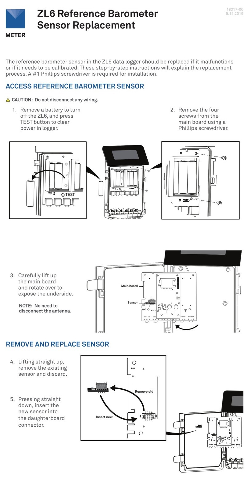
METER ZL6 User manual
METER
METER EM50G User manual
METER
METER ZL6 Use and care manual
METER
METER EM60 Series User manual
METER
METER EM50 Series User manual

METER
METER ZL6 User manual

METER
METER EM50 Series User manual
METER
METER ZL6 Operating and safety instructions
METER
METER ZL6 User manual

METER
METER ZL6 User manual
Popular Data Logger manuals by other brands

Decatur Electronics
Decatur Electronics SpeedSpy User manual & installation guide
MadgeTech
MadgeTech RTDTempX Series Product user guide
Tektronix
Tektronix 308 instruction manual
Videx
Videx LaserLite Pro Hardware manual
IEI Technology
IEI Technology MODAT-550A Series user manual
Thies CLIMA
Thies CLIMA DLU Instructions for use


