Metra Electronics 99-5840CH User manual

INSTALLATION INSTRUCTIONS
99-5840CH
Metra. The World’s Best Kits.®MetraOnline.com © COPYRIGHT 2019 METRA ELECTRONICS CORPORATION REV. 4/16/19 INST99-5840CH
Attention! Let the vehicle sit with the key
out of the ignition for a few minutes before
removing the factory radio. When testing the
aftermarket equipment, ensure that all factory
equipment is connected before cycling the
key to ignition.
KIT FEATURES
• ISO DIN radio provision with pocket
• ISO DDIN radio provision
• Touchscreen display for climate and personalization features
• Painted charcoal
KIT COMPONENTS
• A) Radio trim panel with touchscreen display • B) Radio brackets • C) Pocket • D) Engine start/stop circuit board and cover
• E) (4) #8 x 3/8” Phillips truss-head screws • F) (6) #4 x 1/2” Phillips pan-head screws • G) (4) Panel clips • H) USB cable
• I) HVAC interface and wiring harness (not shown) • J) Antenna adapter (not shown) TOOLS REQUIRED
• Panel removal tool • Phillips screwdriver
• 9/32” socket wrench • Cutting tool
• Torx T-10 screwdriver
TABLE OF CONTENTS
Dash Disassembly ...............................................2-3
Kit Preparation ...................................................4-5
Kit Assembly
–ISO DIN radio provision with pocket ..................6
–ISO DDIN radio provision .....................................6
Axxess Interface installation .............................7-15
Final Assembly ...................................................... 11
WIRING & ANTENNA CONNECTIONS
Wiring Harness: Axxess interface built
into touchscreen
Antenna Adapter: Included with kit
A B C E
D
Ford Mustang (with 8” touchscreen) 2015-2017
F G H
Visit MetraOnline.com for more detailed information about the product and up-to-date vehicle
specific applications

1.800.221.0932
|
MetraOnline.com
1. Open the passenger door and remove
the trim panel from the side of the dash.
(Figure A)
2. Open the glove box and remove the trim
panel on the right side. (Figure B)
3. Unclip and remove the trim/vent dash
panel. (Figure C)
DASH DISASSEMBLY
2
4. Remove the rubber tray cover in front
of the shifter, and then remove the (2)
9/32” screws exposed. (Figure D)
5. Unclip and remove the front side panels
from each side of the center console.
(Figure E)
6. Remove the (2) 9/32” screws from each
side of the center console. (Figure F)
Continued on the next page
(Figure A) (Figure D)
(Figure B) (Figure E)
(Figure C) (Figure F)

REV. 4/16/2019 INST99-5840CH
DASH DISASSEMBLY (CONT.)
3
(Figure I)
(Figure H) (Figure J)
(Figure G)
7. Unclip the shifter trim bezel and slightly
pull it up to clear the center console trim
bezel removal.
8. Open the center console storage
compartment. Unclip the center console
trim bezel, then slide it toward the rear
of the vehicle to remove it. (Figure G)
Note: The complete center console does
not need to be removed. but if it is
desired to be removed, the Push-to-
Start module must be connected when
testing the kit.
9. Remove the plastic tray in front of the
shifter.
10. Remove the center plastic trim
(knockout) between the power outlet
and USB jack. (Figure H)
Ensure that the vehicle is completely
off before proceeding onto the
following (3) steps:
11. Remove the (4) 9/32” screws securing
the radio/climate control panel, and then
unclip, unplug, and remove. (Figure I)
12. Remove the (4) 9/32” screws securing the
display screen, then unplug and remove.
(Figure J)
13. Remove the (4) 9/32” screws securing the
radio chassis, then unplug and remove.
(Figure J)
Continue to Kit Preparation
(4.2” screen shown for illustration only)

1.800.221.0932
|
MetraOnline.com
4
1. Cut and remove the shaded area from
the sub-dash to allow clearance for the
aftermarket radio. (Figure A)
From the factory radio/climate control panel:
2. Remove the (10) T-10 Torx screws
securing the plastic panel cover to the
rear of the panel, and then remove.
(Figure B)
3. Remove the (5) T-10 Torx screws securing
the circuit board, and then remove.
(Figure C)
4. Remove the rubber button membrane
from the back of the engine start/stop
switch panel. (Figure D)
5. Remove the engine start/stop switch
panel. (Figure E)
6. Press in on the (2) retaining tabs inside
the power outlet to remove the inner
portion, and then unsnap the outer ring
and cover. (Figure F)
Continued on the next page
Remove
shaded area
(Figure A) (Figure D)
(Figure B) (Figure E)
(Figure C) (Figure F)
KIT PREPARATION

REV. 4/16/2019 INST99-5840CH 5
KIT PREPARATION (CONT.)
To the 99-5840CH radio trim panel:
7. Attach the engine start/stop switch
panel, and then the rubber button
membrane. (Figure G)
8. Secure the engine start/stop circuit
board
and cover to the switch/cover
assembly using the (6)
#4 x 1/2” Phillips pan-head screws
provided. (Figure H)
9. Insert the
USB
cable into the USB slot,
through the rear. (Figure I)
10. Attach the
(4)
panel clips provided.
(Figure J)
Continue to Kit Assembly
(Figure H) (Figure J)
(Figure G) (Figure I)

1.800.221.0932
|
MetraOnline.com
6
KIT ASSEMBLY
ISO DIN radio provision with pocket
1. Secure the radio brackets to the pocket
using the (4) #8 x 3/8” Phillips truss-head
screws provided. (Figure A)
2. Remove the metal DIN sleeve and trim
ring from the aftermarket radio.
3. Slide the radio into the bracket/pocket
assembly, and then secure it using the
screws supplied with the radio.
(Figure B)
Continue to Axxess
Interface Installation
ISO DDIN radio provision
1. Secure the radio brackets to the radio
using the screws supplied with the
radio. (Figure A)
Continue to Axxess
Interface Installation
(Figure A)
(Figure B)
(Figure A)

REV. 4/16/2019 INST99-5840CH 7
AXXESS INTERFACE INSTALLATION
INTERFACE FEATURES
• Crimping tool and connectors, or solder gun, solder, and heat shrink
• Tape • Wire cutter• Zip ties
TOOLS REQUIRED
Connections ...............................................................................................................................8-9
Installation ..................................................................................................................................10
Programming ...............................................................................................................................11
Touchscreen display operation ..............................................................................................12-13
Steering wheel control settings ............................................................................................14-15
Troubleshooting .......................................................................................................................... 15
INTERFACE COMPONENTS
TABLE OF CONTENTS
• Provides accessory power (12-volt 10-amp)
• Retains R.A.P. (retained accessory power)
• Provides NAV outputs (parking brake, reverse, speed sense)
• Retains audio controls on the steering wheel
• Retains the factory backup camera
• Retains balance
• Micro-B USB updatable
• Axxess interface (built into the touchscreen display)
• 5840 harness
• HVAC interface
• HVAC interface harness
• 16-pin harness with stripped leads
• 54-pin backup camera harness
• 4-pin harness with yellow RCA jacks
• Female 3.5mm connector with stripped leads

1.800.221.0932
|
MetraOnline.com
8
CONNECTIONS
From the 5840 harness to the aftermarket radio:
• Connect the Black wire to the ground wire.
• Connect the Yellow wire to the battery wire.
• Connect the Blue wire to the power antenna wire.
• Disregard the Red and White RCA jacks labeled “RSE/SYNC/SAT”, they will not be used
in this application.
• Disregard the Red and White RCA jacks labeled “FROM 3.5”, they will not be used
in this application.
• Tape off and disregard the following (4) wires, they will not be used in this application:
Green, Green/Black, Purple, Purple/Black
Continued on the next page
From the 16-pin harness with stripped leads to the aftermarket radio:
• Connect the Red wire to the accessory wire.
• Connect the Blue/White wire to the amp turn on wire. This wire must be connected to hear
sound from the factory amplifier.
• If the aftermarket radio has an illumination wire, connect the
Orange/White wire to it.
• Connect the Gray wire to the right front positive speaker output.
• Connect the Gray/Black wire to the right front negative speaker output.
• Connect the White wire to the left front positive speaker output.
• Connect the White/Black wire to the left front negative speaker output.
• Connect the Green wire to the left rear positive speaker output.
• Connect the Green/Black wire to the left rear negative speaker output.
• Connect the Purple wire to the right rear positive speaker output.
• Connect the Purple/Black wire to the right rear negative output.
The following (3) wires are only for multimedia/navigation radios that require these wires.
• Connect the Blue/Pink wire to the VSS/speed sense wire.
• Connect the Green/Purple wire to the reverse wire.
• Connect the Light Green wire to the parking brake wire.
• Tape off and disregard the following (1) wire, it will not be used in this application: Brown

REV. 4/16/2019 INST99-5840CH
CONNECTIONS (CONT)
9
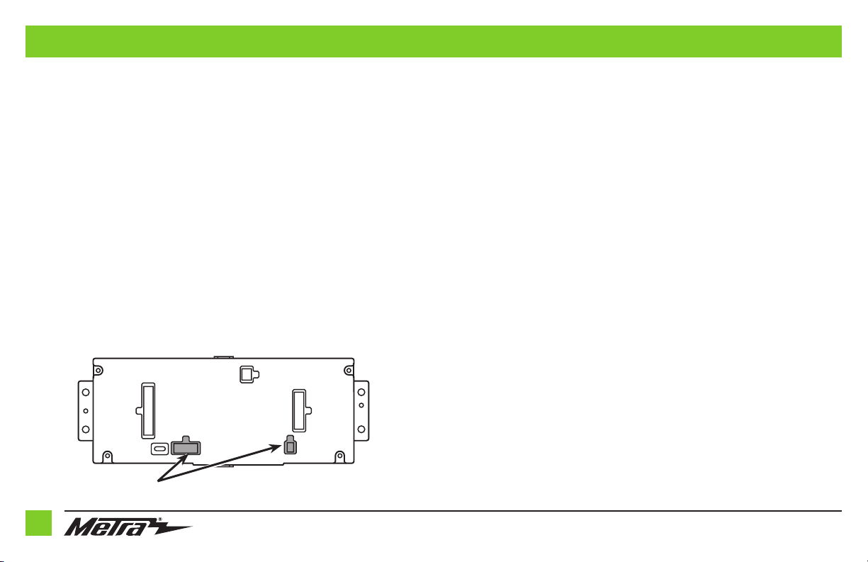
54-pin backup camera harness:
There are two different methods for connecting the factory backup camera.
If retaining the camera to the aftermarket radio is desired:
• Connect the Yellow RCA jack the backup camera input from the aftermarket radio.
If retaining the camera to the touchscreen display is desired:
• Connect the Yellow RCA jack, to the Yellow RCA jack from the 4-pin harness with
yellow RCA jacks
labeled “Rearview camera”.
Note: If this method is chosen, the backup camera option must be enabled in
Configuration Settings.
•
Disregard the Yellow RCA jack labeled “AUX video”, it will not be used in this application
.
3.5mm jack - steering wheel control retention:
The 3.5mm jack is to be used to retain audio controls on the steering wheel control.
• For the radios listed below: Connect the female 3.5mm connector with stripped leads, to
the male 3.5mm SWC jack from the 5840 harness. Any remaining wires tape off and disregard:
•
Eclipse: Connect the steering wheel control wire, normally Brown, to the Brown/White wire of
the connector. Then connect the remaining steering wheel control wire, normally Brown/White,
to the Brown wire of the connector
.
•
Metra OE:
Connect the steering wheel control Key 1 wire
(Gray)
to the
Brown
wire.
•
Kenwood or select JVC with a steering wheel control wire:
Connect the
Blue/Yellow
wire to
the
Brown
wire.
Note:
If your
Kenwood
radio auto detects as a
JVC
, manually set the radio type to
Kenwood
.
See the instructions under changing radio type.
•
XITE:
Connect the steering wheel control SWC-2 wire from the radio to the
Brown
wire.
•
Parrot Asteroid Smart or Tablet:
Connect the 3.5mm jack into the AX-SWC-PARROT (sold separately),
and then connect the 4-pin connector from the AX-SWC-PARROT into the radio
.
Note:
The radio must be updated to rev. 2.1.4 or higher software.
•
Universal “2 or 3 wire” radio:
Connect the steering wheel control wire, referred to as Key-A or
SWC-1, to the
Brown
wire of the connector. Then connect the remaining steering wheel control wire,
referred to as Key-B or SWC-2, to the
Brown/White
wire of the connector. If the radio comes with a
third wire for ground, disregard this wire
.
Note:
After the interface has been programmed to the vehicle, refer to the manual provided with the
radio for assigning the SWC buttons. Contact the radio manufacturer for more information.
• For all other radios: Connect the 3.5mm jack into the port on the radio designated for an external
steering wheel control interface. Refer to the manual provided with the radio if in doubt as to where
the 3.5mm jack goes to.

1.800.221.0932
|
MetraOnline.com
10
I N S TALL ATION
It is highly advisable to read the following steps beforehand, to ensure a clear understanding of
what is to be expected. The following steps must be done in the order that they are numbered.
With the vehicle completely off:
Touchscreen display
1. Connect the 16-pin harness with stripped leads into port “B” in the touchscreen display.
2. Connect the 5840 harness to the wiring harnesses in the vehicle. These harnesses are the
ones removed in step 13 of dash disassembly. Then insert the 5840 harness into port “A” in
the touchscreen display. But do not install this harness until exactly before step 1 from the
Programming section. This is a timed process.
3. Connect the 4-pin harness with yellow RCA jacks into port “C” in the touchscreen display.
4. Disregard ports “D” and “E”, they will not be used in this application.
5. Port “F” is an update port for future firmware upgrades.
HVAC interface
6. Connect the HVAC interface
harness into the HVAC interface, and then to the
wiring harnesses in the vehicle. These harnesses are the ones removed in step 11
of dash disassembly.
a. Then connect the
10-pin harness into the engine start/stop circuit board assembly.
Attention! There are (2) 10-pin connectors, one in the engine start/stop circuit board
assembly, and one in the touchscreen display. Use only the appropriate connector and
disregard the other one. If the incorrect port is accidentally used, the vehicle will need to be
reset by removing the battery for a couple minutes.
Note:
Disregard the 4-pin flat to 4-pin stacked harness, it will not be used in this application.
7. Connect the 6-pin harness from the 5840 harness to the HVAC interface.
8. Connect the female connector from the 54-pin backup camera harness to the wiring
harness in the vehicle. This connector is located behind the factory display screen, which
was removed in step 12 of dash disassembly.
Note: Disregard the male connector, it will not be used in this application.
9. Locate the factory antenna connector in the dash and complete all necessary connections to
the radio. Use the antenna adapter provided to adapt the factory antenna connector to the
aftermarket radio.
AB
C
E
FD
Note: DO NOT CONNECT!

REV. 4/16/2019 INST99-5840CH 11
1. Refer to step 2 from the Installation section.
2. Press the push-to-start button to start the vehicle.
Note: If the Push-to-Start module in the center console has been disconnected, reconnect it.
3. Program the kit:
a. Once the touchscreen display loads up, select the vehicle type.
b. Wait until the radio comes on, and the touchscreen display shows SWC Configured.
This process may take up to 3 minutes.
Note: If the touchscreen display does not load up, or the radio doesn’t come on within
3 minutes, and/or the touchscreen display does not show SWC Configured, check all
connections, then reset the interface and try again. Refer to the Troubleshooting section.
4.
Cycle the key off. If the driver’s door is closed, open and close the door. Cycle the key back on.
5. Test all functions of the installation for proper operation, before reassembling the dash.
1. Connect the USB cable attached to the radio trim panel with touchscreen display, to the
USB port in the back of the radio, if applicable.
2. Secure the completed assembly into the upper dash using the factory hardware removed in
step 12 of dash disassembly.
3. Snap the
radio trim panel with touchscreen display over the completed assembly, and then
reassemble the dash in reverse order of disassembly.
PROGRAMMING FINAL ASSEMBLY

1.800.221.0932
|
MetraOnline.com
12
TOUCHSCREEN DISPLAY OPERATION
Climate Control screen
• This is the climate control screen which will be displayed on the touchscreen display. This is
considered the Main Menu.
• The upper left tab with (3) arrows will take you to the screen where the Heated/Cooled
Seats and Heated Steering are now placed, if applicable.
• The upper right tab with the gear icon will take you to the Configuration Settings screen.
• The climate controls will function in the same manner that they did with the factory climate
controls.
Continued on the next page

REV. 4/16/2019 INST99-5840CH 13
TOUCHSCREEN DISPLAY OPERATION (CONT.)
• Backlight
• For controlling the color of the buttons and back-light intensity.
• Backup Camera
•
Enable/disables the backup camera image to the touchscreen display. Disabled by default
.
• Forward Camera
• To direct where the camera image will be shown, or to disable the camera
• Ambient Lighting Color
• For adjusting the ambient light color in the vehicle
• Steering Wheel Controls
• Remap Buttons – For remapping the steering wheel control buttons
• Dual Assign – For dual assigning the steering wheel control buttons (long button press)
• Select Radio – For auto detecting the radio, or changing the radio type
• Clock
• For setting the clock and hour mode
• System Configuration
• About - Information regarding the software in the kit
• Temperature Unit - To change between Celsius and Fahrenheit
• Digital Amp Gain - For adjusting the output gain to the amplifier
• Reset Vehicle Type - To reset the kit to default settings
Configuration Settings

1.800.221.0932
|
MetraOnline.com
14
STEERING WHEEL CONTROL SETTINGS
Remap Buttons Dual Assign
• The interface has the ability to change the button assignment for the steering wheel
control audio buttons, except Volume-Up and Volume-Down. Follow the prompts on the
touchscreen display to remap the steering wheel control audio button(s) to your liking.
Note: The aftermarket radio may not have all of these commands. Please refer to the
manual provided with the radio, or contact the radio manufacturer, for specific commands
recognized by that particular radio.
• The interface has the capability to assign two functions to a single button, except
Volume-Up and Volume-Down. Follow the prompts on the touchscreen display to
program the button(s) to your liking.
Note: Seek-Up and Seek-Down come programmed as Preset-Up and Preset-Down
for a long button press.
Continued on the next page

REV. 4/16/2019 INST99-5840CH 15
STEERING WHEEL CONTROL SETTINGS (CONT.)
Select Radio
* Note: If the interface shows an Alpine radio, and you do not have an Alpine radio, that means
the interface does not detect a radio connected it, i.e., an open connection. Verify that the 3.5mm
jack is connected to the correct steering wheel jack/wire in the radio.
** Note: The AX-SWC-PARROT is required (sold separately). Also, the Parrot radio must be
updated to rev. 2.1.4 or higher through www.parrot.com.
† Note: If you have a Clarion radio and the steering wheel controls do not work, change the radio
type to the other Clarion radio type; same for Eclipse.
‡ Note: If you have a Kenwood radio and the touchscreen display shows a JVC radio, change the
radio type to Kenwood.
Eclipse (Type 1) †
Kenwood ‡
Clarion (Type 1) †
Sony / Dual
JVC
Pioneer/Jensen
Alpine *
Visteon
Valor
Clarion (Type 2) †
Metra OE
Eclipse (Type 2) †
LG
• To show which brand radio is “auto detected” to the interface, press the “Autodetect”
button. The radio detected will have a filled in circle. If the incorrect radio is shown,
select the proper radio.
• Following is a list of radio manufacturers that the interface presently acknowledges.
Others may be added at a later date. Universal “2 or 3 wire” radios can show up as any of
these radio manufacturers.
Parrot **
XITE
Philips
JBL
Resetting the interface
1. With the vehicle running, press the Reset Vehicle Type button mentioned in
System Configuration.
2. Refer to Programming, step 2, from this point.
TROUBLESHOOTING

INSTALLATION INSTRUCTIONS
99-5840CH
KNOWLEDGE IS POWER
Enhance your installation and fabrication skills by
enrolling in the most recognized and respected
mobile electronics school in our industry.
Log onto www.installerinstitute.com or call
800-354-6782 for more information and take steps
toward a better tomorrow.
®
Metra recommends MECP
certified technicians
Metra. The World’s Best Kits.®MetraOnline.com © COPYRIGHT 2019 METRA ELECTRONICS CORPORATION REV. 4/16/19 INST99-5840CH
If you are having difficulties with the installation
of this product, contact our Tech Support line
either by phone at 1-800-253-TECH, or email at
techsupport@metra-autosound.com. Before
doing so, look over the instruction booklet a
second time and ensure that the installation was
performed exactly as the instruction booklet
is stated. Have the vehicle apart and ready to
perform troubleshooting steps before contacting
Metra/Axxess Tech Support.
Table of contents
Other Metra Electronics Car Video System manuals

Metra Electronics
Metra Electronics 95-7899 User manual

Metra Electronics
Metra Electronics MDF-7603-1 User manual

Metra Electronics
Metra Electronics 95-9612B User manual

Metra Electronics
Metra Electronics WM-BPC User manual

Metra Electronics
Metra Electronics 108-FD3B User manual

Metra Electronics
Metra Electronics 108-FD4CH User manual

Metra Electronics
Metra Electronics 95-7879 User manual

Metra Electronics
Metra Electronics 95-9611B User manual

Metra Electronics
Metra Electronics 99-7612A User manual

Metra Electronics
Metra Electronics 108-GM1G User manual