Metra Electronics 99-6514B User manual

CAUTION!
All accessories, switches, climate
controls panels, and especially air bag indicator
lights must be connected before cycling the
ignition. Also, do not remove the factory radio
with the key in the on position, or while the
vehicle is running.
The World’s Best Kits.®MetraOnline.com © COPYRIGHT 2018 METRA ELECTRONICS CORPORATION REV. 10/22/18 INST99-6514B
INSTALLATION INSTRUCTIONS
99-6514B
KIT FEATURES
• ISO DIN radio provision with pocket
• ISO DDIN radio provision
• Included interface retains factory screen
• Painted matte black to match factory finish
Note: Does not retain sound from “Driver Convenience Group”
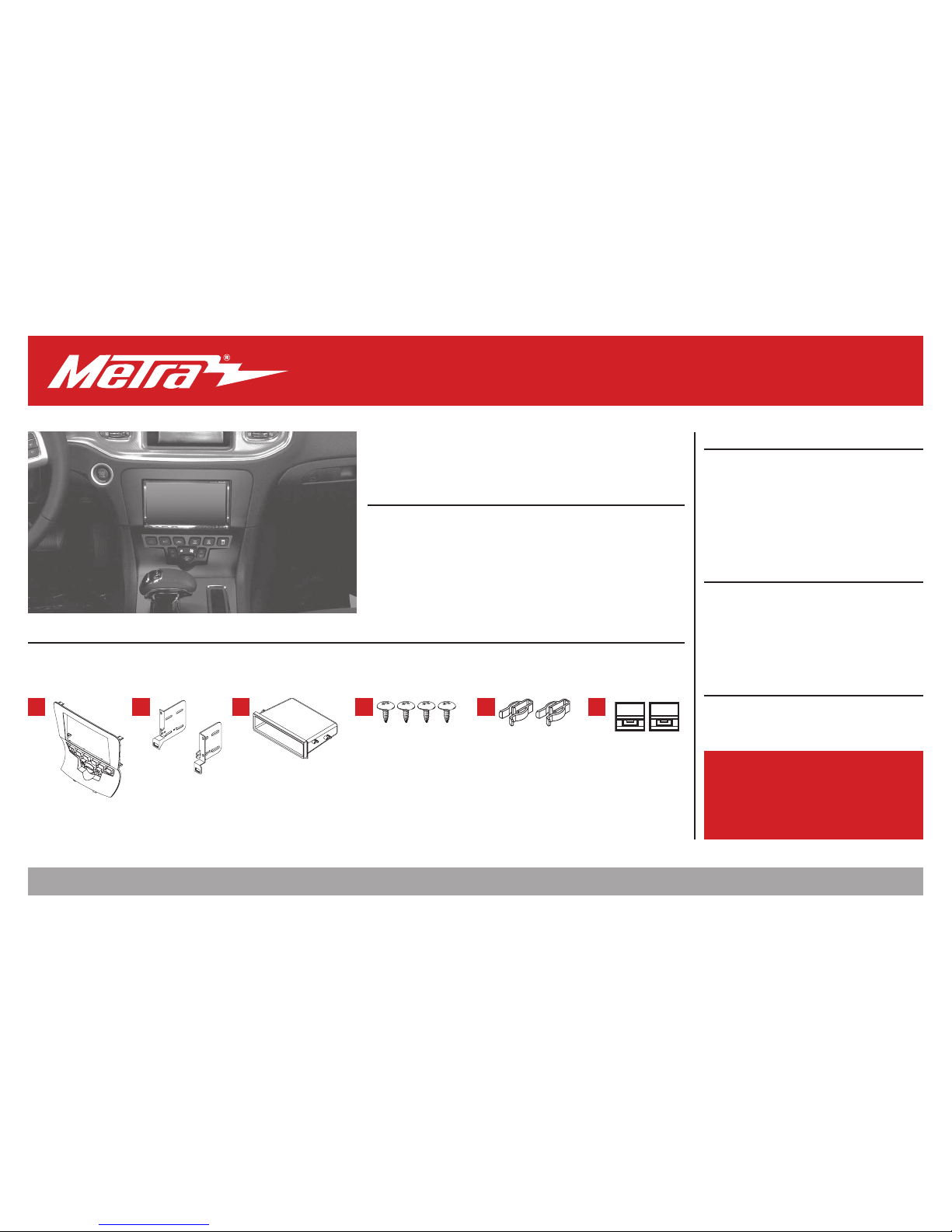
KIT COMPONENTS
• A) Radio trim panel • B) Radio brackets • C) Pocket • D) (4) #8 x 3/8” Phillips screws • E) (2) Plastic panel clips • F) (2) Metal panel clips
• Axxess interface and harness (not shown)
TOOLS REQUIRED
• Panel removal tool • Phillips screwdriver
• T-30 Torx screwdriver
TABLE OF CONTENTS
Dash Disassembly ..................................................2
Kit Assembly
– ISO DIN radio provision with pocket .................3
– ISO DDIN radio provision ....................................3
Axxess Interface Installation .............................4-8
WIRING & ANTENNA CONNECTIONS
Wiring Harness: Interface and harness included
Antenna Adapter: 40-EU10*
Steering wheel control interface: ASWC-1*
Backup camera retention: AX-CHRYCAM-1*
* Sold separately
A B C D E F
Dodge Charger 2011-2014
1.800.221.0932
|
MetraOnline.com
2
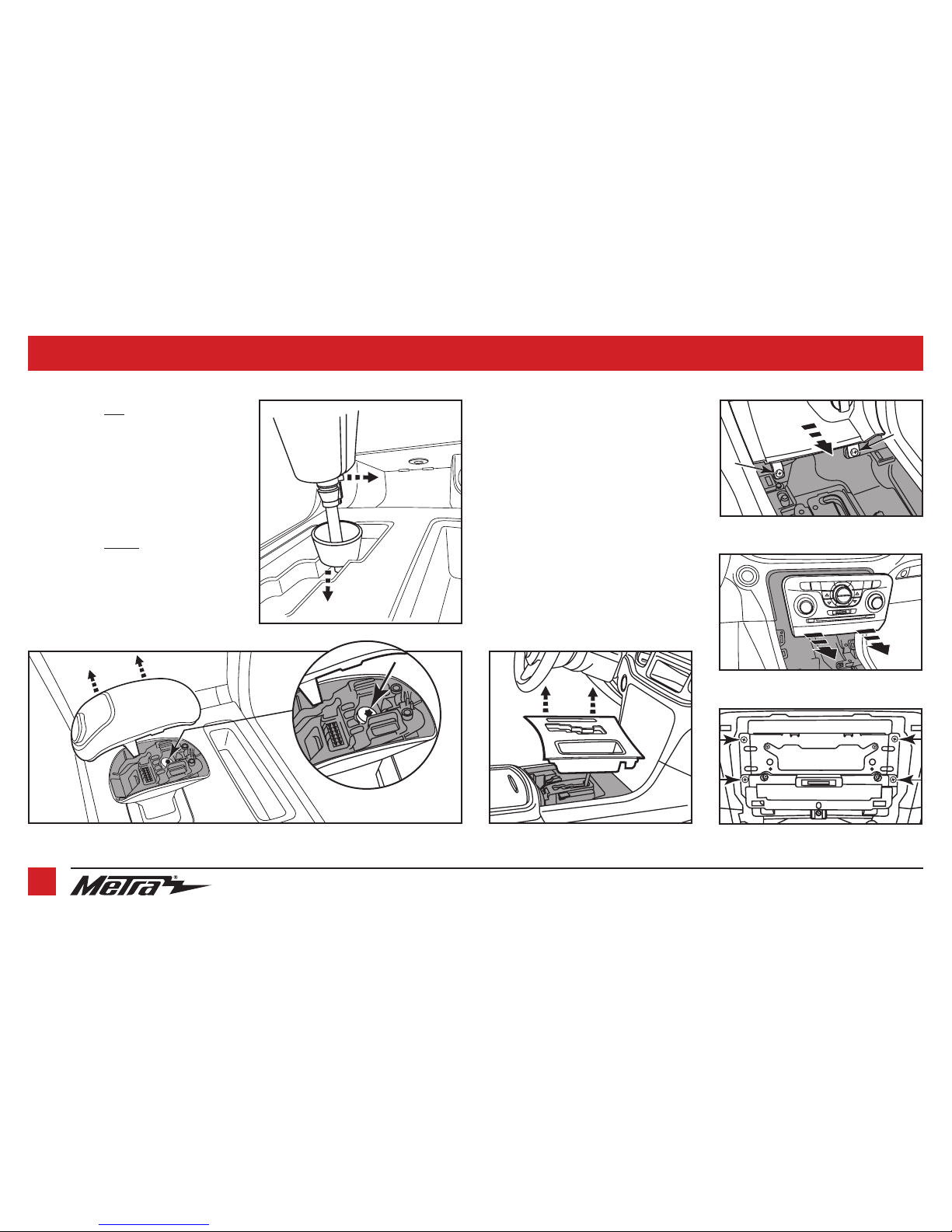
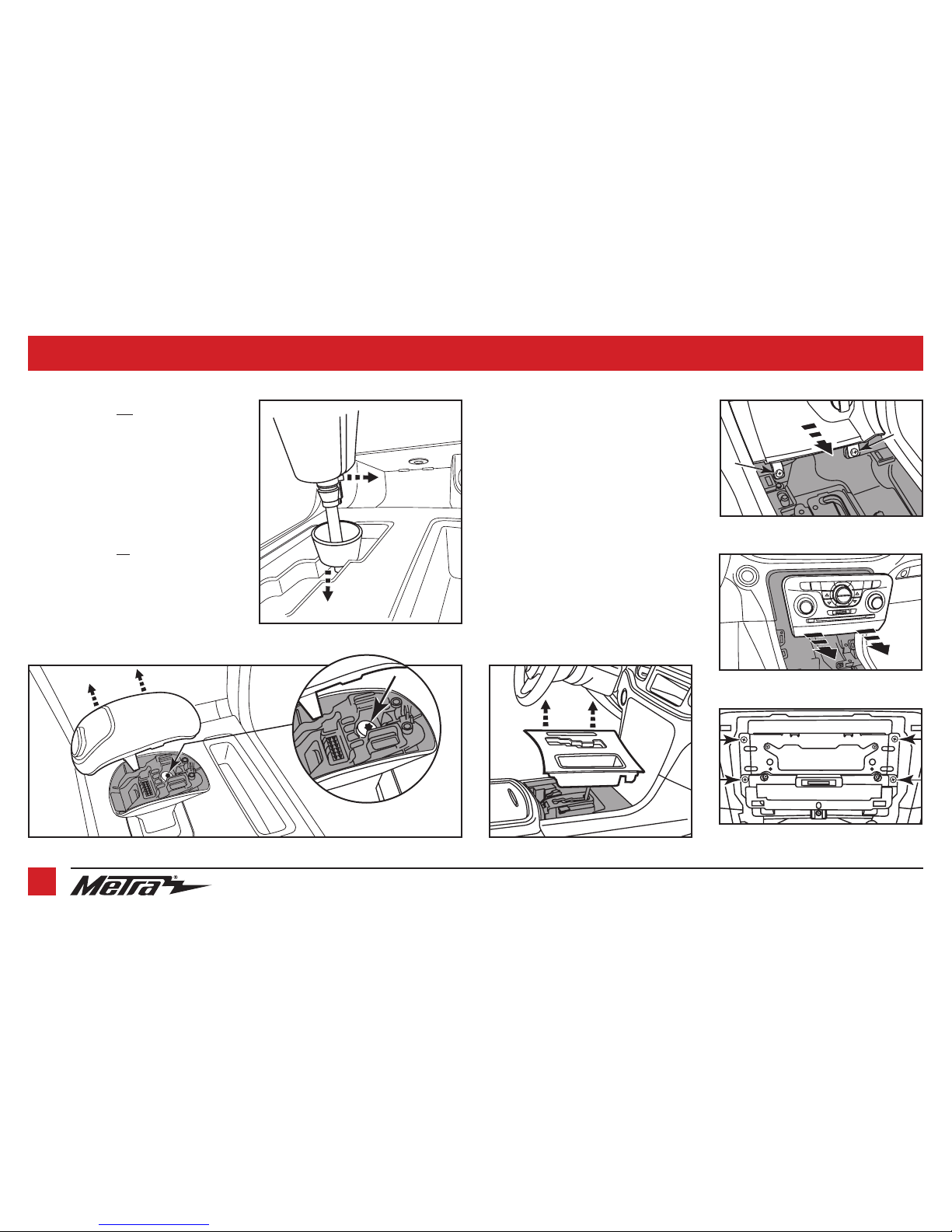
DASH DISASSEMBLY
1. For vehicles
with
an 8 speed
transmission:
Unclip and remove the top of the shift
knob assembly. Next, remove the (1)
exposed T-30 Torx screw from the shift
knob and then pull up on the knob to
remove. (Figure A)
For vehicles
without
an 8 Speed
transmission:
Push the collar down at the base of the
shift knob and remove the pin then pull
up on shift knob to remove. (Figure B)
(Figure A)
(Figure D)
(Figure B)
(Figure E)
(Figure F)
(Figure C)
2. Unclip and remove the shifter trim
panel. (Figure C)
3.
Remove (2) Phillips screws securing the
pocket below the climate controls then
unclip and remove the pocket. (Figure D)
4. Unclip, unplug, and remove the factory
radio/climate control panel. (Figure E)
5. Remove (4) Phillips screws securing
the radio chassis, and then unplug and
remove the chassis. (Figure F)
Continue to Kit Assembly

REV. 10/22/2018 INST99-6514B 3
KIT ASSEMBLY
(Figure A)
(Figure B)
(Figure C)
ISO DIN radio provision with pocket
1. Attach the provided clips to the
radio
trim panel
(metal clips at top and plastic
at the bottom). (Figure A)
2. Secure the
pocket
to the
radio brackets
with the (4) #8 x 3/8” Phillips pan head
screws supplied. (Figure B)
3. Remove the metal DIN sleeve and trim
ring from the aftermarket radio.
4. Slide the radio into
radio brackets
and
secure with the screws supplied with the
radio. (Figure C)
Continue to Axxess Interface Installation
ISO DDIN radio provision
1. Attach the provided clips to the
radio
trim panel
(metal clips at top and plastic
at the bottom). (Figure A)
2. Secure the radio to the
radio brackets
using the screws supplied with the
radio. (Figure B)
Continue to Axxess Interface Installation
(Figure A)
(Figure B)
Clip
locations
Clip
locations

1.800.221.0932
|
MetraOnline.com
4
AXXESS INTERFACE INSTALLATION
• Provides accessory power (12-volt 10-amp)
• Retains R.A.P. (retained accessory power)
• Used in amplified or non-amplified systems
• Provides NAV outputs (parking brake, reverse, and speed sense)
• Prewired ASWC-1 harness (ASWC-1 sold separately)
• Retains balance and fade
• Ability to add an aftermarket backup camera or additional video input
• Retains the factory display screen
• Micro “B” USB updatable
Note: Does not retain sound from “Driver Convenience Group”
Connections ..............................................................................................................................................5
Installation ...............................................................................................................................................6
Programming ...........................................................................................................................................6
Final assembly .........................................................................................................................................6
Audio level adjustment ...........................................................................................................................6
Screen operation ......................................................................................................................................6
Video option screen .................................................................................................................................7
Updating ...................................................................................................................................................8
INTERFACE FEATURES TABLE OF CONTENTS
• Crimping tool and connectors, or solder gun, solder, and heat shrink
• Tape • Wire cutter • Zip ties • Small flat-blade screwdriver
TOOLS REQUIRED
• Axxess interface
• 16-pin harness with stripped leads
• 6514 harness
INTERFACE COMPONENTS

REV. 10/22/2018 INST99-6514B 5
From the 16-pin harness with stripped leads to the aftermarket radio:
• Connect the Red wire to the accessory wire.
Note: If also installing an ASWC-1 (sold separately), there will be a Red wire on the 6514
harness to connect as well.
• Connect the Orange/White wire to the illumination wire, if applicable.
• If the vehicles equipped with a factory amplifier, connect the Blue/White wire to the amp
turn-on wire.
The following (3) wires are for aftermarket multimedia/navigation radios that require these wires:
• Connect the Light Green wire to the parking brake wire.
• Connect the Blue/Pink wire to the VSS or speed sense wire.
• Connect the Green/Purple wire to the reverse wire.
• Tape off and disregard the following (9) wires, they will not be used in this application:
Brown, White, White/Black, Gray, Gray/Black, Purple, Purple/Black, Green, Green/Black
From the 6514 harness to the aftermarket radio:
• Connect the Black wire to the ground wire.
• Connect the Yellow wire to the battery wire.
• Connect the Gray wire to the right front positive speaker output
• Connect the Gray/Black wire to the right front negative speaker output
• Connect the White wire to the left front positive speaker output
• Connect the White/Black wire to the left front negative speaker output
• Connect the Green wire to the left rear positive speaker output.
• Connect the Green/Black wire to the left rear negative speaker output.
• Connect the Purple wire to the right rear positive speaker output.
• Connect the Purple/Black wire to the right rear negative speaker output.
• Tape off and disregard the following (4) wires, they will not be used in this application:
Purple, Purple/Black, Green, Green/Black
• Disregard the Yellow RCA jack labeled (1), it will not be used in this application.
• Connect the Yellow RCA jack labeled (2) to either an aftermarket backup camera, or an
AUX video input.
• Connect the Red & White RCA jacks to the audio AUX-IN jacks.
12-pin pre-wired ASWC-1 harness:
• The 12-pin harness is to be used along with the optional ASWC-1 (sold separately) to retain
steering wheel controls. If the ASWC-1 is not being used, disregard this harness. If it will be
used, please refer to the ASWC-1 instructions for programming. Disregard the harness that
comes with the ASWC-1.
CONNECTIONS TO BE MADE
1.800.221.0932
|
MetraOnline.com
6
INSTALL ATION
PROGRAMMING
SCREEN OPERATION
FINAL ASSEMBLY
Attention! For models with a 8-inch screen, update the interface via the Axxess Updater
available at axxessinterfaces.com. Select “8-inch screen” once prompted to. Instructions to
update the interface are available at the end of this instruction booklet.
With the key in the off position:
1. Connect the 16-pin harness with stripped leads, and the 6520 harness, into the interface.
2. Connect the factory “White” 4-pin harness removed in step 5 of Dash Disassembly to the
“Black” connector from the interface.
Note: The display screen will not function without this connection.
3. Connect the 6514 harness to the wiring harness in the vehicle.
4.
Connect the climate control harness from the vehicle to the 99-6514B radio trim panel. This is the
harness that was removed in step 4 of dash disassembly
.
5. Locate the factory antenna connector in the dash and complete all necessary connections to
the radio. Metra recommends using the proper mating adapter from Metra.
Note: If an ASWC-1 (sold separately) will be used, do not connect it until the interface is
programmed and fully functional.
1. Secure the completed radio assembly to the dash using the factory hardware.
2. Reassemble the dash in reverse order of disassembly using the 99-6514B panel.
1. When the interface first boots up, the factory screen will go through a boot up sequence for
a few moments. Do not touch any controls during this process.
2. Test all functions of the installation for proper operation, before reassembling the dash. For
amplified models, also refer to the “Audio Level Adjustment” section.
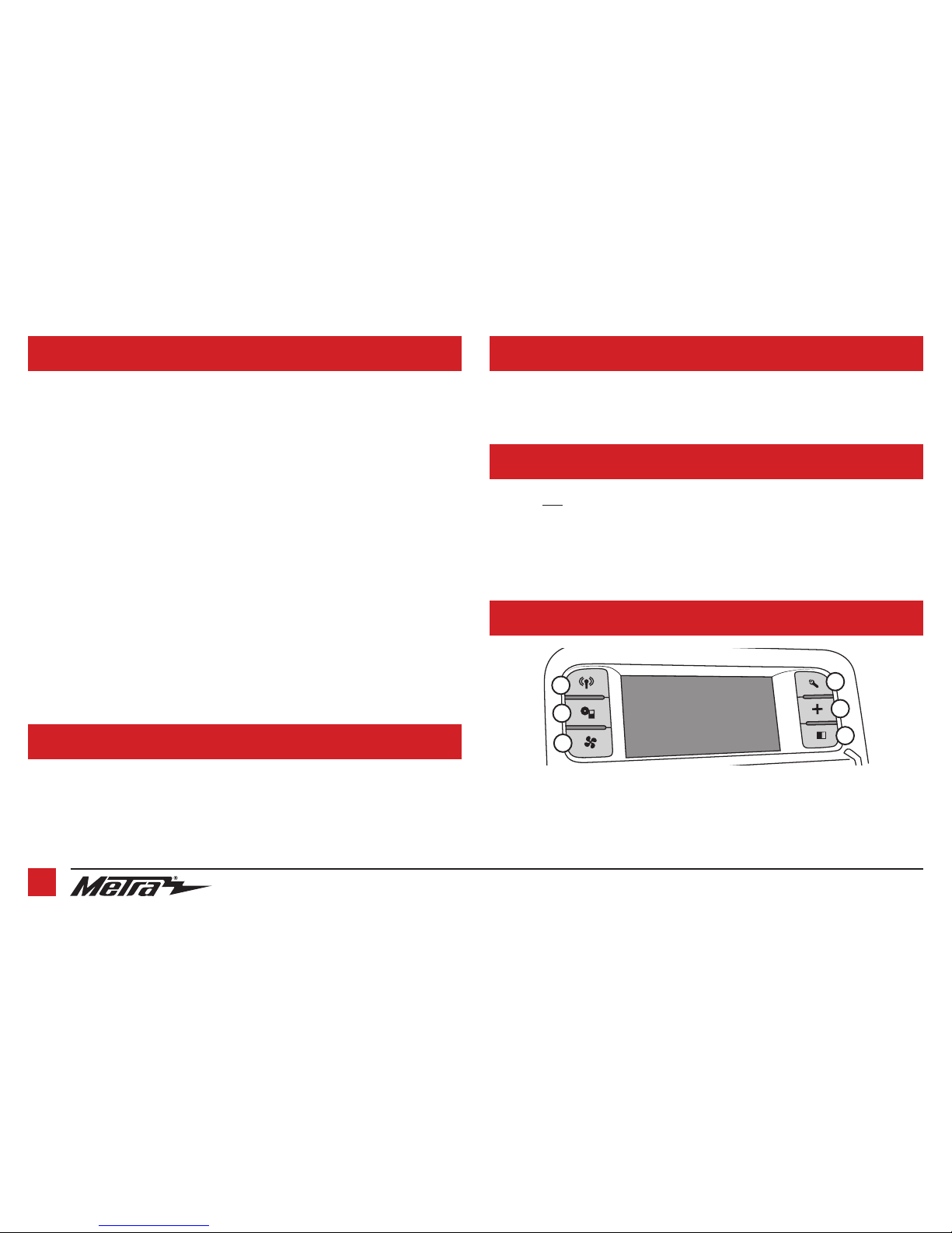
1. Radio button – Show the current time
2. Player button – Not used in this application
3. Climate button –
Takes you to the climate screen
4. Setting button – Takes
you to the setting screen
5. More button – Shows the outside temperature
and current time
6. Screen Off – Turns the display off
1
2
3
4
5
6
AUDIO LEVEL ADJUSTMENT
For models
with
a factory amplifier:
1. With the vehicle and radio turned on, turn the volume up 3/4 of the way.
2. With a small flat-blade screwdriver, adjust the potentiometer clockwise to raise the audio
level; counterclockwise to lower the audio level.
3. Once at a desired level, audio level adjustment is complete.

REV. 10/22/2018 INST99-6514B 7
VIDEO OPTION SCREEN
2. Once in the Customize menu, select
Video Input 2 to select a desired source.
Please note that Video Input 1 is not
available with this kit. Press About to
view the current software of the kit, and
also the VIN of the vehicle. (Figure B, C,
and D)
Note 1: The backup camera input is
controlled by data and will only activate
while the vehicle is in reverse.
Note 2: AUX video is controlled by data
and will only work while the vehicle is in
park.
1. The settings screen provides access to
some of the factory settings retained,
and also the options available with the
kit. Select Customize to access options
available. (Figure A)
(Figure A)
(Figure C)
(Figure B) (Figure D)

KNOWLEDGE IS POWER
Enhance your installation and fabrication skills by
enrolling in the most recognized and respected
mobile electronics school in our industry.
Log onto www.installerinstitute.com or call
800-354-6782 for more information and take steps
toward a better tomorrow.
®
Metra recommends MECP
certified technicians
IMPORTANT
If you are having difficulties with the installation of this product,
please call our Tech Support line at 1-800-253-TECH. Before
doing so, look over the instructions a second time, and make
sure the installation was performed exactly as the instructions
are stated. Please have the vehicle apart and ready to perform
troubleshooting steps before calling.
The World’s Best Kits.®MetraOnline.com © COPYRIGHT 2018 METRA ELECTRONICS CORPORATION REV. 10/22/18 INST99-6514B
INSTALLATION INSTRUCTIONS
99-6514B
UPDATING
Attention: In order to update the Axxess interface, the interface must have power from the vehicle.
• Download and install the Axxess Updater from axxessinterfaces.com.
• Connect the USB-MINI-CAB update cable (sold separately) between the interface and the computer. The cable will connect into
the micro-B USB port inside the interface.
• Remove the main connector from the vehicle. This will remove power from the interface.
• Reconnect the main harness back to the vehicle, putting power back to the interface.
• From the Start Menu of the computer, click on “Axxess Updater”, and then click “Update Firmware”. The interface will begin to
update at this point.
Note 1: If 30 seconds elapses before you finish this step, you will need to remove power from the interface, then reapply
power, and then start the update process again.
Note 2: Please note which firmware downloaded to the interface. This will help in troubleshooting, if need be.
¡PRECAUCIÓN! Todos los accesorios, interruptores,
paneles de controles de clima y especialmente las
luces del indicador de las bolsas de aire deben estar
conectados antes ciclar la ignición. Además, no
quite el radio de fábrica con la llave en la posición o
de encendido ni con el vehículo funcionando.
The World’s Best Kits.®MetraOnline.com © COPYRIGHT 2018 METRA ELECTRONICS CORPORATION REV. 10/22/18 INST99-6514B
INSTRUCCIONES DE INSTALACIÓN
99-6514B
CARACTERÍSTICAS DEL KIT
• Provisión de radio ISO DIN con cavidad
• Provisión de radio ISO DDIN
• La interfase incluida conserva la pantalla de fábrica
• Pintura negro mate para igualar el acabado de fábrica
Nota:
No retiene el sonido de “Driver Convenience Group”
COMPONENTES DEL KIT
• A) Panel de moldura de radio • B) Soportes del radio • C) Cavidad • D) (4)Tornillos Phillips #8 de 3/8” • E) (2) Clips de plástico del panel
• F) (2) Clips de panel de metal • Interfase y arnés Axxess (no se muestra) HERRAMIENTAS REQUERIDAS
• Herramienta para quitar paneles
• Destornillador Phillips • Destornillador Torx T-15
INDICE
Desmontaje del tablero ........................................2
Ensamble del kit
– Provisión de radio ISO DIN con cavidad ............3
– Provisión de radio ISO DDIN ...............................3
Instalación de la interfase Axxess ....................4-8
CABLEADO Y CONEXIONES DE ANTENA
Arnés de cableado: Interfase y arnés incluido
Adaptador de antena: 40-EU10*
Interfase de control en volante: ASWC-1*
* Se venden por separado
A B C D E F
Dodge Charger 2011-2014
1.800.221.0932
|
MetraOnline.com
2
DESMONTAJE DEL TABLERO
1. Para vehículos
con
transmisión de 8
velocidades:
Desenganche y quite la parte superior
del ensamble de la perilla de la palanca
de velocidades. A continuación, quite (1)
tornillo Torx T-30 de la perilla de la palanca
de velocidades, luego jale la perilla hacia
arriba para quitarla. (Figura A)
Para vehículos
sin
transmisión de 8
velocidades:
Empuje el collar hacia abajo en la
base de la perilla de la palanca de
velocidades y quite la clavija, luego jale
hacia arriba la perilla de la palanca de
velocidades para quitarla. (Figura B)
(Figura A)
(Figura D)
(Figura B)
(Figura E)
(Figura F)
(Figura C)
2.
Desenganche y quite el panel de moldura
de la palanca de velocidades. (Figura C)
3.
Quite los (2) tornillos Phillips que sujetan
la cavidad debajo de los controles del
clima, luego desenganche y quite la
cavidad. (Figura D)
4. Desenganche, desenchufe y quite el
panel de radio de fábrica/control del
clima. (Figura E)
5. Quite los (4) tornillos Phillips que sujetan
el chasís del radio, y luego desconecte y
quitar el chasis. (Figura F)
Continúe con el Ensamble del Kit
Table of contents
Languages:
Other Metra Electronics Car Video System manuals

Metra Electronics
Metra Electronics 108-FD3B User manual

Metra Electronics
Metra Electronics 99-5840CH User manual

Metra Electronics
Metra Electronics 95-7899 User manual

Metra Electronics
Metra Electronics 95-7879 User manual

Metra Electronics
Metra Electronics 108-FD4CH User manual

Metra Electronics
Metra Electronics 108-GM1G User manual

Metra Electronics
Metra Electronics 99-8153 User manual

Metra Electronics
Metra Electronics 99-7612A User manual

Metra Electronics
Metra Electronics 95-9612B User manual

Metra Electronics
Metra Electronics 95-9611B User manual


