4 GV 71 en 9
6 REMOVAL & MOUNTING THE
ACTUATOR
The actuator is attached to the valve according to the manual
for actuator with body assembly and plug stem adjustment .
Several types of Metso actuators can be used with suitable
clamps. Refer to the model VD spring-diaphragm and VC
double acting cylinder actuator manuals for further informa-
tion on their installation, maintenance and operation.
A. Actuator removal for Reverse <air to open, stem
retract> actuator (Fig. 12)
Lift up to the valve plug more than 20 % from the
seat ring, using by specified air pressure.
Loosen the stem locknut (5**) and socket head
screws (1a**)and hexagon nuts (1b**).
Remove the stem clamp (1**).
Shut off and disconnect air supply line.
Support actuator with the suitable lifting device.
Remove the yoke nut (3**).
Remove the actuator from the valve body assembly.
B. Actuator removal for Direct <air to close, stem
extend> actuator (Fig. 12)
Shut off and disconnect the air supply lines and
accessories.
Loosen stem lock nut (5**) and stem socket head
screws (1a**) and hexagon nuts (1b**).
Remove the stem clamp (1**).
Support actuator with the suitable lifting device.
Remove the yoke nut (3**).
Remove the actuator from the valve body assembly.
C. Actuator replacement (mounting)
Mount the new or repaired actuator on top of the
bonnet, using a suitable lifting device.
Insert the yoke nut and tightly fasten the yoke by
turning the yoke nut clockwise using tightening tools.
Connect air line and accessories.
Standard valve construction
1. With the handwheel or pneumatically, push the
valve stem and plug to be slightly touched with seat
ring to make sure if valve is fully closed.
2. With the handwheel or pneumatically, stroke the
actuator to the fully open.
3. Measure the maximum distance between the valve
stem and actuator top stem.
4. Calculate the gap (measured value – rated travel =
gap 1)
5. Move down the top stem so that the distance bet-
ween the valve stem and actuator top stem should
be gap 1
6. Fit the clamp to align with both stems thread
7. Line up the stroke indicator with the clamp indicator
arrow and check actuator for operation.
8. Tighten the socket head screws after adjusted the
rated stroke.
Pilot valve construction
In VDR and VDD
1. With the handwheel or pneumatically, push the
valve stem and plug to be slightly touched with seat
ring to make sure if valve is fully closed. And mark
the valve stem end location by a line on the yoke or
travel indicator.
2. And move up the top stem. And mark the valve stem
end location by a line on the yoke or travel indicator
after valve stem is moved by a spring inside pilot
plug.
3. Measure the distance between two lines, which is
gap 2.
4. Stroke the actuator to the fully open.
5. Measure the maximum distance between the valve
stem and actuator top stem.
6. Calculate the gap (measured value – rated travel –
gap 2 = gap 3)
7. Move down the top stem so that the distance bet-
ween the valve stem and actuator top stem should
be gap 2
8. Fit the clamp to align with both stems thread
9. Close the valve fully.
10. Line up the stroke indicator with the clamp indicator
arrow and check actuator for operation.
11. Tighten the socket head screws after adjusted the
rated stroke.
Tighten stem socket head screws (1a**) and hexa-
gon nuts (1b**) with stem lock nut (5**).
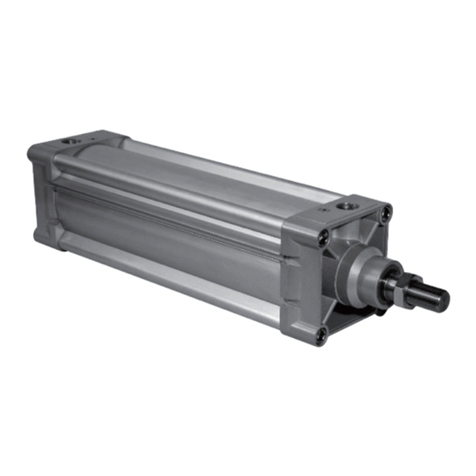
E. Type 'VC' Springless Cylinder, Double Acting Actuator
This actuator is springless cylinder, double acting actuator,
can use the 1/4", 3/8", 1/2" NPT port according to specified
on the data sheet for all air lines.
Refer to the model VC double acting cylinder actuator man-
uals for further information on their installation, mainte-
nance and operation.
CAUTION:
Beware of the plug movement!
Do not use air pressure higher than what specified on the
identification plate.
Fig. 11 Measurement of Gap 2
CAUTION:
Avoid to turn the valve plug and stem when plug is on
seat ring to prevent the seating line from being dama-
ged.


