4.7 Option “Y” - Keyed Output
150 – 600 lb•in (12 - 25 lb•ft; 17 - 68 Nm) actuators are
supplied with a 3/4” female square output coupling; when
the “Y” option is selected they are supplied with a 15mm
female keyed output.
1000 – 3000 lb•in (83 - 250 lb•ft; 113 - 339 Nm) models are
supplied with a 1”female square output coupling; when the
“Y”option is selected they are supplied with a 20mm female
keyed output.
This option is factory installed only.
4.8 Option “Z” – Handwheel Override
P/N VC009097, P/N VC009098
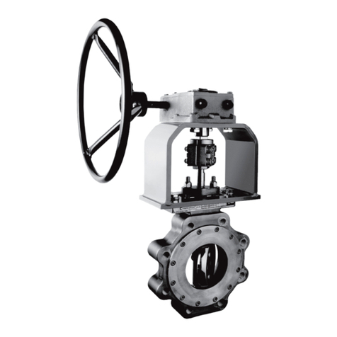
All V-Series actuators are supplied with a wrench-operated
manual override shaft. If the Handwheel Override option is
selected the shaft is replaced by a declucthable shaft and a
six-inch handwheel (see IMO-I9090 for additional reference).
WARNING
WHENEVER WORKING INSIDE THE ACTUATOR BE SURE TO FOLLOW
ALL GUIDELINES, AND HEED ALL WARNINGS IN THIS MANUAL. IF
INSTALLING AN OPTION KIT, BE SURE TO READ AND FOLLOW THE
SUPPLIED INSTRUCTIONS CAREFULLY AND HEED ANY ADDITIONAL
WARNINGS.
This option can also be installed in the eld; for 150 –
600 lb•in (12 - 25 lb•ft; 17 - 68 Nm) models order kit P/N
VC009097 and for 1000 – 3000 lb•in (83 - 250 lb•ft; 113 - 339
Nm) models order kit P/N VC009098.
4.9 Voltage
115 VAC or 230 VAC. V-Series actuators are rated for full
torque at +/- 10% of the nominal voltage at 60 Hz. Note:
operation at 50 Hz will proportionally decrease the duty
cycle and increase the cycle time. V-Series actuators are
rated for a minimum of 75%* duty cycle at 60 Hz at 104˚F
(40˚C).
* 55% duty cycle for 3000 lb•in actuators.
5. GENERAL OPERATING INFORMATION
For enclosure specications and dimensions, see (Tables
1-2 and Figure 13).
5.1 Enclosure Ratings and Product
Certications
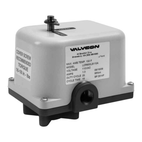
Metso oers two versions of V-Series actuator enclosures:
the “W” enclosure is weathertight, and the “WX” enclosure
which is weathertight and explosion-proof.
5.2 Wiring
WARNING
VALVCON AC VOLTAGE ACTUATORS USE REVERSING INDUCTION
MOTORS WHICH CAUSE HIGH VOLTAGES. DEVICES CONNECTED
TO TERMINAL 3 AND TO TERMINAL 4 MUST BE RATED FOR
MINIMUM 250 VAC 440 VAC FOR 230 VAC APPLICATIONS.
CONTROLLERS WITH SOLID STATE OUTPUTS MUST BE RATED
FOR MORE THAN 250 VAC. WE STRONGLY RECOMMEND THAT
RELAY OUTPUTS BE USED ON CONNECTED DEVICES. DUE TO THE
INDUCTION FEEDBACK VOLTAGE, MULTIPLE ACTUATORS CAN NOT
BE WIRED IN PARALLEL. SEPARATE ISOLATED CONTACTS MUST BE
PROVIDED FOR EACH ACTUATOR. IF THE ACTUATOR IS DRIVEN BY
CONTACTS ON A PC OR PLC, MAKE SURE THE CONTACTS HAVE THE
PROPER RATINGS.
5.3 Duty Cycle and Motor Protection
V-Series actuators can operate continuously for up to 15
minutes at 104˚F (40˚C). After 15 minutes of continuous
operation they are rated for 75% duty cycle operation at
104˚F and for 30 starts per minute. Duty cycles decrease at
temperatures in excess of 104˚F. Duty cycle is the maximum
proportion of“on”time and the minimum required“o”time
to prevent thermal overloading. Actuators with cycle times
of 30 seconds must rest at least 10 seconds between cycles.
Higher temperature applications decrease duty cycle.
AC motors contain thermal overload protection. Exceeding
the rated duty cycle may cause the thermal overload switch
to temporarily remove power to the motor and cause it to
stall. After the motor cools, the actuator will resume normal
operation. The thermal protector is a safety device, designed
for infrequent use. Constant tripping of the thermal overload
protector may cause premature motor failure.
5.4 Operating Temperature Limits
V-Series actuators are designed to operate in ambient
environments between -40˚F (-40˚C) and 150˚F (65˚C). In
outdoor applications where ambient temperatures exceed
80˚F, actuators should be shielded from direct sunlight.
In applications with high media temperatures, insulating
blankets, heat shields and/or extended mounting shafts
should be used to maintain ambient temperatures at the
actuator within normal operating limits.
Heaters and thermostats are recommended for all outdoor
applications and may also be used to dry condensation in
high humidity environments.
5.5 Actuator Mounting
The actuator may be mounted in any position including
upside-down. It must be rmly secured to a direct mount
ange or sturdy mounting bracket. A minimum of four bolts
with lock washers should be used to secure the actuator to the
bracket. Flexibility in the bracket is not allowed, and backlash,
IMO 10/17
10 IMO-I5500 EN


