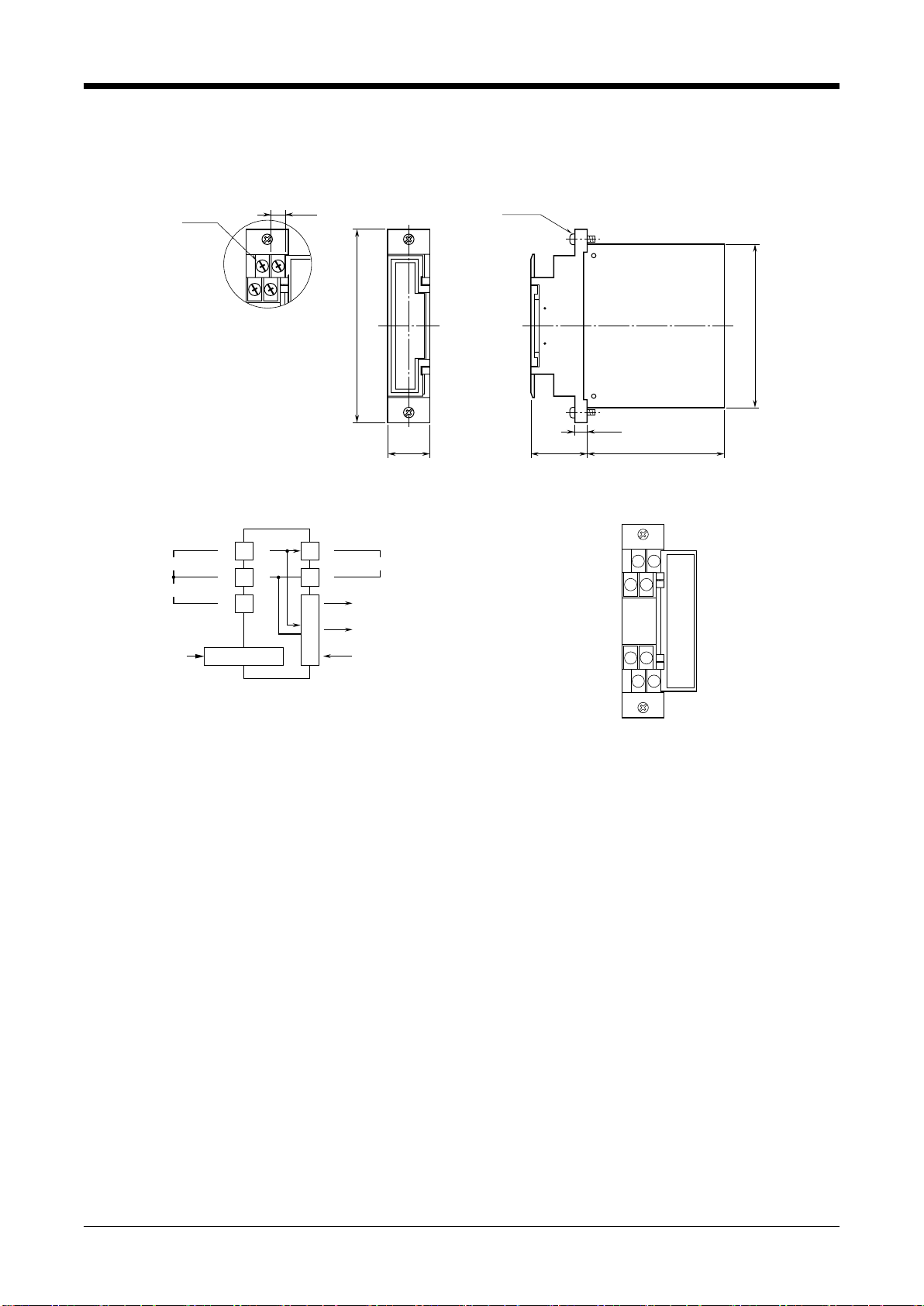
manuals.online logo
Brands
  1. Home
  2. •
  3. Brands
  4. •
  5. MG
  6. •
  7. Transmitter
  8. •
  9. MG 18JPA User manual

MG 18JPA User manual

BEFORE USE ....
Thank you for choosing us. Before use, please check con-
tents of the package you received as outlined below.
If you have any problems or questions with the product,
please contact our sales office or representatives.
■PACKAGE INCLUDES:
Signal conditioner ...............................................................(1)
■MODEL NO.
Confirm Model No. marking on the product to be exactly
what you ordered.
■INSTRUCTION MANUAL
This manual describes necessary points of caution when
you use this product, including installation and connection,
hardware setting, and basic maintenance procedures.
When you need to change software settings, please refer to
the Operation Manual for Model PU-2x (EM-9255), Section
A.
POINTS OF CAUTION
■POWER INPUT RATING & OPERATIONAL RANGE
• Locate the power input rating marked on the product and
confirm its operational range as indicated below:
24V DC rating: 24V ±10%, approx. 90mA
■GENERAL PRECAUTIONS
• Before you remove the unit or mount it, turn off the power
supply and input signal for safety.
■ENVIRONMENT
• Indoor use.
• When heavy dust or metal particles are present in the
air, install the unit inside proper housing with sufficient
ventilation.
• Do not install the unit where it is subjected to continuous
vibration. Do not subject the unit to physical impact.
• Environmental temperature must be within -5 to +55°C
(23 to 131°F) with relative humidity within 30 to 90% RH
in order to ensure adequate life span and operation.
■WIRING
• Do not install cables close to noise sources (relay drive
cable, high frequency line, etc.).
• Do not bind these cables together with those in which
noises are present. Do not install them in the same duct.
■AND ....
• The unit is designed to function as soon as power is sup-
plied, however, a warm up for 10 minutes is required for
satisfying complete performance described in the data
sheet.
COMPONENT IDENTIFICATION
Body
Specifications
Front Cover
(Connection diagram
behind)
■FRONT VIEW (with cover open)
1
78
56
2
34
Modular Jack
INSTALLATION
Use Standard Rack (model: 18BXx or 18KBXx).
FREQUENCY TRANSMITTER
(eld-programmable) MODEL 18JPA
EM-1873 Rev.7 P. 1 / 5
MG CO., LTD. www.mgco.jp
5-2-55 Minamitsumori, Nishinari-ku, Osaka 557-0063 JAPAN
INSTRUCTION MANUAL
TERMINAL CONNECTIONS
Connect the unit as in the diagram below or refer to the connection diagram behind the front cover.
■EXTERNAL DIMENSIONS unit: mm (inch)
110 (4.33 )
93 (3.66)
24 (.94)
7 (.28)
78 (3.07)32 (1.26)
8–M3.5
SCREW
7 (.28)
2–M3
SCREW
■CONNECTION DIAGRAM
PU-2x
MODULAR JACK
+
–
INPUT
1
3
2
+
SENSOR EXCITATION
+
–
OUTPUT 2
POWER
OUTPUT 1
OUTPUT 2
5
6
CONNECTOR
■TERMINAL ASSIGNMENTS
12
34
78
56
18JPA
EM-1873 Rev.7 P. 2 / 5
MG CO., LTD. www.mgco.jp
5-2-55 Minamitsumori, Nishinari-ku, Osaka 557-0063 JAPAN
WIRING INSTRUCTIONS
■SCREW TERMINAL
Torque: 0.8 N·m
CHECKING
1) Terminal wiring: Check that all cables are correctly con-
nected according to the connection diagram.
2) Power input voltage: Check voltage supplied to the rack
(model: 18BXx or 18KBXx). For the DC power source, be
sure that the ripple level is within 10% p-p.
3) Input: Check that the input signal is within 0 – 100% of
the full-scale.
4) Output: Check that the load resistance meets the de-
scribed specifications.
ADJUSTMENT PROCEDURE
This unit is calibrated at the factory to meet the ordered
specifications, therefore you usually do not need any cali-
bration, unless you need to match the signal to a receiving
instrument or conduct regular calibration.
Zero and span are adjusted with using the Programming
Unit (model: PU-2x).
Refer to the Operation Manual for Model PU-2x for expla-
nations how to use the programmer.
■WARNING ON USE OF THE PROGRAMMING UNIT
• Be sure to disconnect the Programming Unit before you
turn on/off power supply to the unit.
• The output signal is held when the Programming Unit is
connected. You need to disconnect when confirming cur-
rent output values.
■HOW TO CALIBRATE THE OUTPUT 1
Use a signal source and measuring instruments of sufficient
accuracy level. Turn the power supply on and warm up for
more than 10 minutes.
There is no need of adjusting the Output 2.
• Fine Output Calibration
Using the Programming Unit (ITEM 19, 20)
ITEM 19 is for Zero, and ITEM 20 is for Span.
1) Turn the unit into Program mode (ITEM 01).
2) Apply simulated 0% input. Increase/decrease values
(default: 0%) at ITEM 19 until the output signal is cali-
brated to actual 0%.
3) Apply simulated 100% input. Increase/decrease value
(default: 100%) at ITEM 20 until the output signal is cali-
brated to actual 100%.
4) Apply simulated 0% input again and check 0% output.
5) When 0% value is changed, repeat the above procedure
2) – 4).
The 0% value may be shifted when the output span is
greater than the input span (gain > 1).
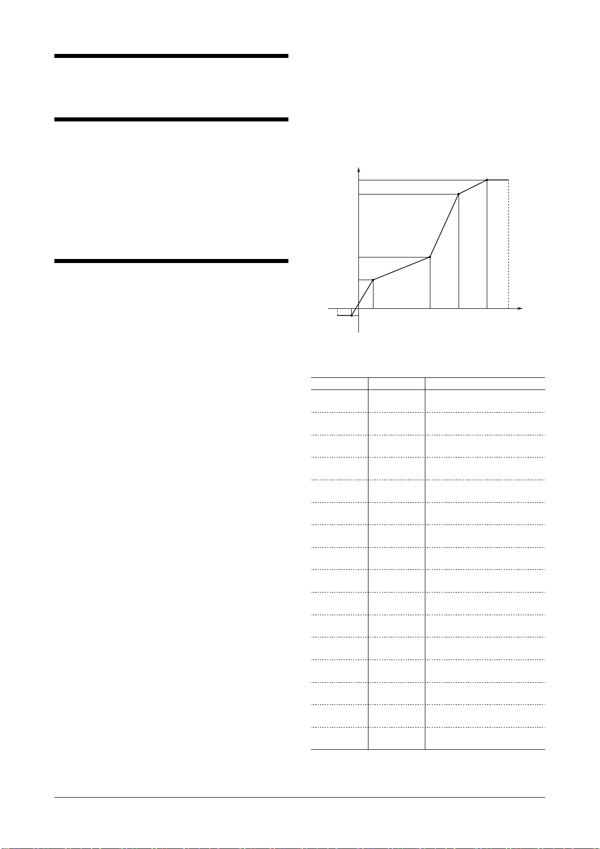
• Using Linearization Table
Please have the PU-2x Operation Manual ready at hand.
Max. 16 calibration points defined by sets of input and out-
put values can be programmed. Use only necessary number
of points, arranged in order from the smallest input value.
Enable use of the linearization table (ITEM 10: PA-2:
curved) in order to activate the settings.
X (nn) : Input Signal in %
Y (nn) : Output Signal in %
X or Y : -15.00 to +115.00%
-15% 0
X01
X02 X03 X04 X05 +115%
Y01
Y02
Y03
Y04
+100% Y05
INPUT
OUTPUT
-5%
Figure 1. Linearization Table
[GROUP 01]
ITEM MDFY. DATA EXAMPLE
60
61
P
P
X (01) : XXX.XX
Y (01) : XXX.XX
62
63
P
P
X (02) : XXX.XX
Y (02) : XXX.XX
64
65
P
P
X (03) : XXX.XX
Y (03) : XXX.XX
66
67
P
P
X (04) : XXX.XX
Y (04) : XXX.XX
68
69
P
P
X (05) : XXX.XX
Y (05) : XXX.XX
70
71
P
P
X (06) : XXX.XX
Y (06) : XXX.XX
72
73
P
P
X (07) : XXX.XX
Y (07) : XXX.XX
74
75
P
P
X (08) : XXX.XX
Y (08) : XXX.XX
76
77
P
P
X (09) : XXX.XX
Y (09) : XXX.XX
78
79
P
P
X (10) : XXX.XX
Y (10) : XXX.XX
80
81
P
P
X (11) : XXX.XX
Y (11) : XXX.XX
82
83
P
P
X (12) : XXX.XX
Y (12) : XXX.XX
84
85
P
P
X (13) : XXX.XX
Y (13) : XXX.XX
86
87
P
P
X (14) : XXX.XX
Y (14) : XXX.XX
88
89
P
P
X (15) : XXX.XX
Y (15) : XXX.XX
90
91
P
P
X (16) : XXX.XX
Y (16) : XXX.XX
Modication Code
S: Modifiable at any time.
P: Modifiable only when the MAINTENANCE SWITCH is in
the “PRG” mode.
18JPA
EM-1873 Rev.7 P. 3 / 5
MG CO., LTD. www.mgco.jp
5-2-55 Minamitsumori, Nishinari-ku, Osaka 557-0063 JAPAN
PROGRAMMABLE ITEMS
The following items can be monitored and programmed. For detailed explanations, please refer to the Operation Manual for
Model PU-2x (EM-9255), Section A.
[GROUP 01]
ITEM MDFY. DATA INPUT DISPLAY CONTENTS
01 S MAINTENANCE SWITCH (lock command)
0 MTSW: MON.MODE MONITOR mode: data monitoring only
1 MTSW: PRG.MODE PROGRAM mode: “P” marked data modifiable
02 P Alphabets & No. TG: XXXXXXXXXX Tag name entry (10 characters max.)
03
05
06
P
D
D
Number (%)
No input
No input
OUTPER XXX.XX
INPPER XXX.XX
INPFRQ XXXXXX
Output status monitor (%) & simulation output
Input status monitor (%)
Input frequency monitor, same unit as selected in ITEM 11
10 P LINEARIZATION
1 PA-1: straight Without
2 PA-2: curved With (ITEM 60 to 91 for data input)
11 P COARSE FREQUENCY RANGE SELECTION
0
1
2
FRQRNG: 10mHz
FRQRNG: 100mHz
FRQRNG: 1.0Hz
0 – 10 mHz
0 – 100 mHz
0 – 1 Hz
3
4
5
FRQRNG: 10Hz
FRQRNG: 100Hz
FRQRNG: 1.0kHz
0 – 10 Hz
0 – 100 Hz
0 – 1 kHz
6
7
FRQRNG: 10kHz
FRQRNG: 100kHz
0 – 10 kHz
0 – 100 kHz
13 P Percentage DRPOUT XXX.XX Low-end cutout adjustment, 0.00 – 100.00%
14
15
P
P
Actual value
Actual value
SCLLOW XXXXXX
SCLHIG XXXXXX
Input range scaling 0% value
Input range scaling 100% value
Up to 150% of the coarse range selected in ITEM 11. Use the
same unit.
18 P Number SMPLRATE XXX Sampling rate modification for irregular pulse input (No. of
pulses to be counted during one rotation of input flowmeter)
Frequency range ≤ 100 Hz: 1 – 255
Frequency range 0 – 1 kHz: 1 – 25
Frequency range 0 – 10 kHz: 1 – 2
19 P Percentage FINZER Fine zero adjustment
Initial status shows actual bias (%). When data is entered, out-
put (%) is shown.
20 P Percentage FINSPN Fine span adjustment
Initial status shows actual gain (%). When data is entered, out-
put (%) is shown.
LINEARIZATION TABLE
60
61
P
P
Percentage
Percentage
X (01) : XXX.XX
Y (01) : XXX.XX
Input 1
Output 1
:
:
91
:
:
P
:
:
Percentage
:
:
Y (16) : XXX.XX
:
:
Output 16
Modication Code
D: No modification (writing) possible. Used only for monitoring (reading).
S: Modifiable at any time.
P: Modifiable only when the MAINTENANCE SWITCH is in the “PRG” mode.
18JPA
EM-1873 Rev.7 P. 4 / 5
MG CO., LTD. www.mgco.jp
5-2-55 Minamitsumori, Nishinari-ku, Osaka 557-0063 JAPAN
MAINTENANCE
Regular calibration procedure is explained below:
■CALIBRATION
Warm up the unit for at least 10 minutes. Apply 0%, 25%,
50%, 75% and 100% input signal. Check that the output
signal for the respective input signal remains within accu-
racy described in the data sheet. When the output is out of
tolerance, recalibrate the unit according to the “ADJUST-
MENT PROCEDURE” explained earlier.
LIGHTNING SURGE PROTECTION
We offer a series of lightning surge protector for protec-
tion against induced lightning surges. Please contact us to
choose appropriate models.
18JPA
EM-1873 Rev.7 P. 5 / 5
MG CO., LTD. www.mgco.jp
5-2-55 Minamitsumori, Nishinari-ku, Osaka 557-0063 JAPAN

Other MG Transmitter manuals

MG Mini-M M2EXV User manual

MG

MG Mini-M M2EXV User manual

MG M6NPA User manual

MG

MG M6NPA User manual

MG BCT User manual

MG

MG BCT User manual

MG BR User manual

MG

MG BR User manual

MG 17PE User manual

MG

MG 17PE User manual

MG M60EWVS User manual

MG

MG M60EWVS User manual

MG M3-UNIT Series User manual

MG

MG M3-UNIT Series User manual

MG M3SVS User manual

MG

MG M3SVS User manual

MG W5VS User manual

MG

MG W5VS User manual

MG M6NVF User manual

MG

MG M6NVF User manual

MG KWRS2 User manual

MG

MG KWRS2 User manual

MG M6SXM User manual

MG

MG M6SXM User manual

MG M3-UNIT Series User manual

MG

MG M3-UNIT Series User manual

MG SVF User manual

MG

MG SVF User manual

MG FRT User manual

MG

MG FRT User manual

MG M6SWVS User manual

MG

MG M6SWVS User manual

MG Mini-M M2VF3 User manual

MG

MG Mini-M M2VF3 User manual

MG B5MS User manual

MG

MG B5MS User manual

MG 10MS User manual

MG

MG 10MS User manual

MG W5LCS User manual

MG

MG W5LCS User manual

MG W5TS User manual

MG

MG W5TS User manual

MG HR User manual

MG

MG HR User manual

MG 10AC User manual

MG

MG 10AC User manual

MG 10RS User manual

MG

MG 10RS User manual

Popular Transmitter manuals by other brands

Vega VEGABAR 86 Quick setup guide

Vega

Vega VEGABAR 86 Quick setup guide

elero LumeroTel operating instructions

elero

elero LumeroTel operating instructions

Kramer SID-X3N user manual

Kramer

Kramer SID-X3N user manual

Long Range Systems T9560 EZ user manual

Long Range Systems

Long Range Systems T9560 EZ user manual

Linear Multi-Code 4120 installation instructions

Linear

Linear Multi-Code 4120 installation instructions

Caliber PMT 563BT manual

Caliber

Caliber PMT 563BT manual

YOKOGAWA Dpharp vigilantplant EJA310A user manual

YOKOGAWA

YOKOGAWA Dpharp vigilantplant EJA310A user manual

Endress+Hauser Mycom CLM 152 operating instructions

Endress+Hauser

Endress+Hauser Mycom CLM 152 operating instructions

Miratron T–2 operating guide

Miratron

Miratron T–2 operating guide

jotron TA-7650C Maintenance and Repair Manual

jotron

jotron TA-7650C Maintenance and Repair Manual

AMG AMG4783RN-CWDMn instruction manual

AMG

AMG AMG4783RN-CWDMn instruction manual

Canon EOS 5D - Focusing Screen Ee-A instruction manual

Canon

Canon EOS 5D - Focusing Screen Ee-A instruction manual

Omega CDTX-90 Series user guide

Omega

Omega CDTX-90 Series user guide

Status SEM1605TC User instructions

Status

Status SEM1605TC User instructions

Vaisala HUMICAP MMT310 user guide

Vaisala

Vaisala HUMICAP MMT310 user guide

Evikon PluraSens E2618-O2 user manual

Evikon

Evikon PluraSens E2618-O2 user manual

REL 518-D instruction manual

REL

REL 518-D instruction manual

Okit F11A user manual

Okit

Okit F11A user manual

manuals.online logo
manuals.online logoBrands
  • About & Mission
  • Contact us
  • Privacy Policy
  • Terms and Conditions

Copyright 2025 Manuals.Online. All Rights Reserved.