TERMINAL CONNECTIONS
Connect the unit as in the diagram below or refer to the connection diagram on the side of the unit.
Do not interconnect negative sides of input and output terminals (via grounding terminals e.g.) as they are not of the same
potential level.
Ground the terminal 4 for RFI protection if necessary. When grounded, dielectric strength between output signal line and
ground is of 50V DC, though it is of 500V AC when not grounded.
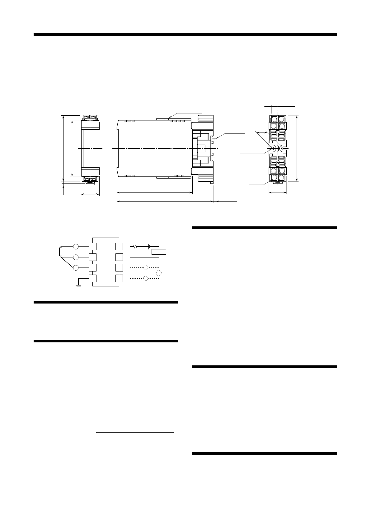
■EXTERNAL DIMENSIONS unit: mm (inch)
12
34
7
6
8
5
3 (.12)2 (.08)
26 (1.02) 107 (4.21) 26 (1.02)
93 (3.66)
15
(.59)
2–4.5 (.18)
HOLE
15 (.59) deep
DIN RAIL
35mm wide
[3.3 (.13)]
8–M3.5
SCREW
93 (3.66)
CLAMP
(top & bottom)
137 (5.39)
80 (3.15)
•When mounting, no extra space is needed between units.
7.8 (.31)
■CONNECTION DIAGRAM
1
2
A
B
B
RTD
3
4
7
8
+
–
mA
MONITOR
+
–
+
–
6
5
LOAD
OUTPUT
24V DC
4 – 20mA DC
WIRING INSTRUCTIONS
■SCREW TERMINAL
Torque: 0.8 N·m
CHECKING
1) Terminal wiring: Check that all cables are correctly con-
nected according to the connection diagram.
2) Input: Check voltage across the terminal 1 – 2 with a
sensitive voltmeter (With 20°C or 68°F, approx. 220mV
with Pt 100, approx. 110mV with Pt 50 Ω).
If RTD wires are broken, the output goes over 100% (be-
low 0% with downscale) due to burnout function. Check
leadwires in such a case.
3) Output: Check that the load is within the permissible
limit including wiring resistance.
Load Resistance (Ω) = Supply Voltage (V) – 12 (V)
0.02 (A)
(including leadwire resistance)
4) When you check the output signal, connect an ammeter
of which the internal resistance is of 10Ω max. to the
monitor terminals.
ADJUSTMENT PROCEDURE
This unit is calibrated at the factory to meet the ordered
specifications, therefore you usually do not need any cali-
bration.
For matching the signal to a receiving instrument or in case
of regular calibration, adjust the output as explained in the
following.
■HOW TO CALIBRATE THE OUTPUT SIGNAL
Use a signal source and measuring instruments of sufficient
accuracy level. Turn the power supply on and warm up for
more than 10 minutes.
1) ZERO: Apply 0% input and adjust output to 0%.
2) SPAN: Apply 100% input and adjust output to 100%.
3) Check ZERO adjustment again with 0% input.
4) When ZERO value is changed, repeat the above proce-
dure 1) – 3).
MAINTENANCE
Regular calibration procedure is explained below:
■CALIBRATION
Warm up the unit for at least 10 minutes. Apply 0%, 25%,
50%, 75% and 100% input signal. Check that the output
signal for the respective input signal remains within accu-
racy described in the data sheet. When the output is out of
tolerance, recalibrate the unit according to the “ADJUST-
MENT PROCEDURE” explained earlier.
LIGHTNING SURGE PROTECTION
We offer a series of lightning surge protector for protec-
tion against induced lightning surges. Please contact us to
choose appropriate models.
BR
EM-3113 Rev.7 P. 2 / 2
MG CO., LTD. www.mgco.jp
5-2-55 Minamitsumori, Nishinari-ku, Osaka 557-0063 JAPAN


