MGG Maxi Dog Fencing System Setup guide
MGG Maxi Dog Fencing System
Operating and Training Guide
PLEASE READ THIS ENTIRE GUIDE BEFORE BEGINNING
Suitable for up
to 10 acres

2
Thank you for choosing an MGG Maxi Dog Fencing System
Table of Contents
Components ..................................................................................... 3
Other items you may need .............................................................. 3
How the system works .................................................................... 4
Key Definitions .......................................................................... ...... 4
Operating Guide
Locating the Fence Transmitter ..................................................... 5
Laying out the system ..................................................................... 5
Sample layouts ................................................................................. 6
Positioning the boundary wire ........................................................ 7
Connecting the wires to the Fence Transmitter ............................ 8
Preparing the Receiver Collar ......................................................... 9
Setting the boundary width and testing the Receiver Collar ........ 10
Installing the boundary wire ............................................................ 11
Placing the boundary flags .............................................................. 13
Fitting the Receiver Collar ................................................................13
Training Guide
Be patient with your dog .................................................................. 14
Day 1: boundary flag awareness ..................................................... 14
Days 2 to 4: continue boundary flag awareness ........................... 15
Days 5 to 8: distraction phase ........................................................ 15
Days 9 to 14: unleashed supervision ............................................. 16
Days 14 to 30: monitoring your dog’s behaviour .......................... 16
Taking your dog out of the area ...................................................... 16
Trouble-shooting .............................................................................. 17
Short loop test .................................................................................. 18
Locating a break in the wire ............................................................ 18
Terms of use and limitation of liability ........................................... 19
Caution .............................................................................................. 19
Machines Gadgets and Gizmows Ltd contact details ................... 20
Please retain your original invoice for warranty purposes. MGG offer a return-
to-base warranty for the collar-receivers of 3 months and the transmitters for
12 months against faulty manufacture.
3
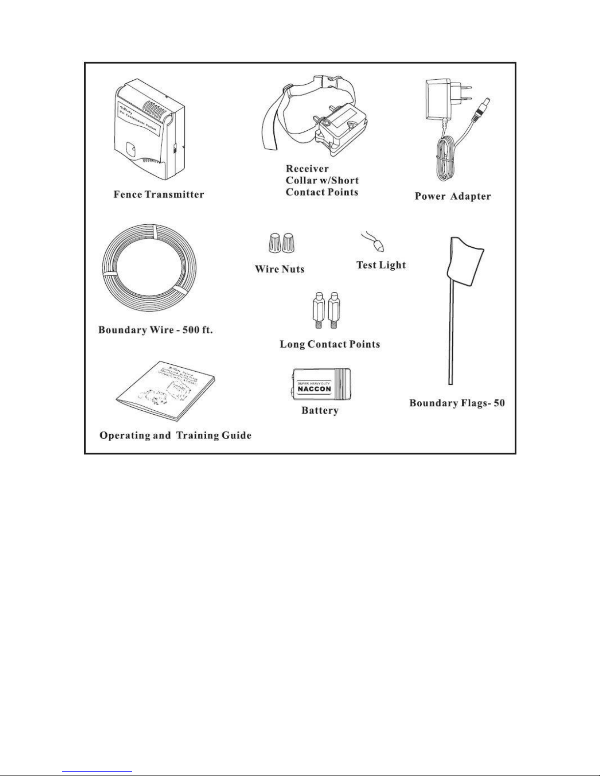
Components
Other Items You May Need
Additional
Tape measure
Drill & mounting hardware
Shovel or lawn edger
Pliers
Wire stripping pliers
Scissors
Lighter
Electrical tape
Additional wire nuts or MGG Waterproof connectors
Ground rod and clamp
Waterproofing compound (e.g. silicone caulk)
PVC pipe or water hose
Circular saw with masonry blade
Patching compound
Staple gun
Non-metallic collar and leash
4
How the System Works
The In-Ground Radio Fence has been proven safe, comfortable, and effective for all dogs over
7.5Kg. The system works by producing a radio signal from the Fence Transmitter through up to
1200 metres of Boundary Wire. The Boundary Wire is buried or attached to a fixed object to
enclose the Dog Area. You temporarily define the Dog Area with Boundary Flags for a visual aid
in training your dog when no visual boundary exists. Your dog wears a Receiver Collar with
Contact Points that touch his neck, and, once trained, is allowed to roam freely in the Dog Area.
When your dog reaches the Warning Zone, the Receiver Collar gives a warning beep. If your dog
continues into the Static Correction Zone, a safe Static Correction will be delivered through the
Contact Points to get his attention until he returns to the Dog Area.
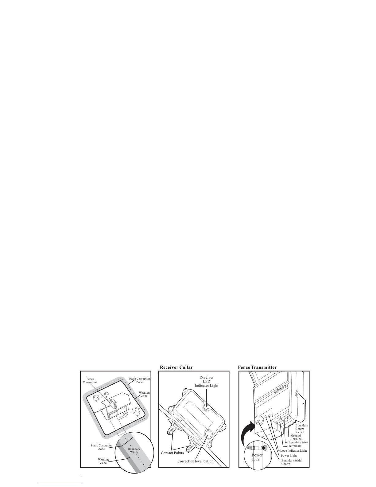
Key Definitions
Fence Transmitter: The device that transmits the radio signal through the Boundary Wire.
Dog Area: The area within the Warning Zone where your dog can roam freely.
Warning Zone: The outer edge of the Dog Area where your dog’s Receiver Collar begins to
beep, warning him not to go into the Static Correction Zone.
Static Correction Zone: The zone beyond the Warning Zone where your dog’s Receiver Collar
will emit a Static Correction, signalling him to return to the Dog Area.
Boundary Width: The combination of the Warning Zone and the Static Correction Zone.
Receiver Collar: The device that receives the radio signal from the Boundary Wire.
Correction Level Button: The button to adjust the level of Static Correction your dog receives in
the Static Correction Zone.
Receiver LED Indicator Light: The light that indicates the level of correction at which the
Receiver Collar is set.
Contact Points: The contacts through which the Receiver Collar delivers the safe Static
Correction when your dog moves into the Static Correction Zone.
Power Jack: The jack where the Power Adapter plugs into the Fence Transmitter. The Fence
Transmitter is powered by a standard 110-240 volt outlet.
Boundary Control Switch: The switch to adjust according to the length of Boundary Wire used.
Ground Terminal: The terminal where the Ground Wire connects to the Fence Transmitter.
Boundary Wire Terminals: The terminals where the Boundary Wires connect to the Fence
Transmitter in order to complete a continuous loop.
Loop Indicator Light: The light that indicates that the Boundary Wire makes a complete loop,
enabling the signal to be transmitted.
Boundary Width Control: The knob that adjusts the width of the Warning and Static Correction
Zones.
Note: Adjusting the knob does not change the level of Static Correction on the Receiver Collar.

5
OPERATING GUIDE
Locating the Fence Transmitter
Step 1 Placing the Fence Transmitter
In a dry, well ventilated protected area (1A, 1B).
In an area where temperatures do not fall below freezing (e.g. garage, basement, shed,
closet).
Secured to a stationary surface using appropriate mounting hardware (not included).
At least 1 metre from large metal objects or appliances as these items may interfere with the
signal consistency (1C).
Once you have mounted the Fence Transmitter, the Boundary Wire must exit the building. This
can be accomplished via a window or through a 4mm hole drilled through the wall. Ensure the drill
path is clear of any utilities. Make sure the Boundary wire is not cut off or pinched by a window,
door, or garage door, as this can damage it over time.
To prevent fires and electrical hazards, install the Fence Transmitter in buildings that are in
accordance with state and local electrical codes
Lay Out the System
Step 2 Basic Planning Tips
The Boundary Wire MUST start
at the Fence Transmitter and
make a continuous loop back
to it. (2A).
Design a layout that is suitable
for your yard. Sample layouts
are provided in this section.
Always use gradual turns at the
corners to produce a more
consistent boundary (2B). Do
not use sharp turns, as this will
cause gaps in your boundary.
Avoid making passageways
too narrow for your dog to
move about freely, (e.g. along
the sides of a house).
The Receiver Collar can be activated inside the house if the Boundary Wire runs along the
outside wall of the house. If this occurs, remove your dog’s Receiver Collar before bringing
him inside, decrease the range using the Boundary Width Control or consider an alternative
layout. Spurious signals from some household appliances can also activate the collar so
it is recommended that the collar be removed when you dog is inside the house.
6
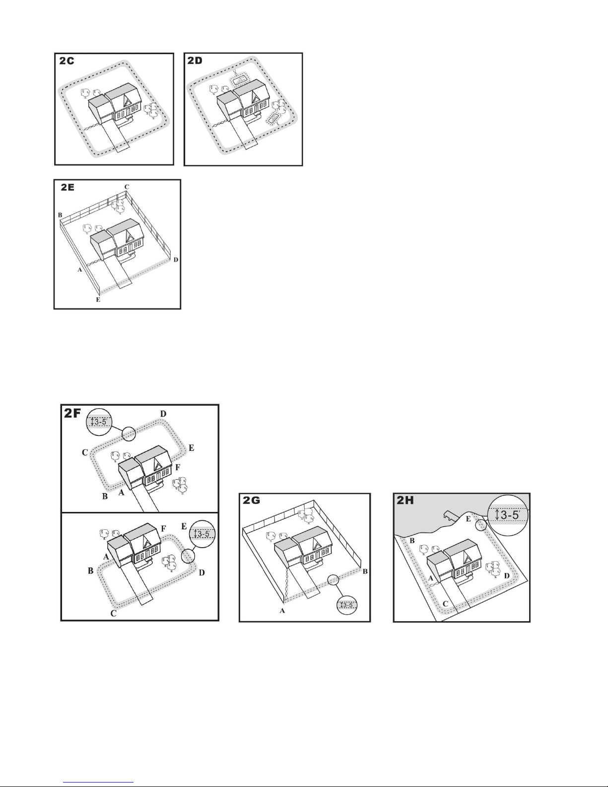
Sample Layouts
Sample 1: Perimeter Loop (Single Loop)
The Perimeter Loop is the most common
layout. This will allow your dog to freely and
safely roam your entire property (2C). It can
also protect gardens, pools and landscaping
(2D).
Sample 2: (2E) Perimeter Loop Using Existing Fence (Single Loop)
This layout allows you to include your existing fence as part of your
layout and keep your dog from jumping out or digging under your
existing fence. It reduces the amount of wire which will need to be
buried. From the Fence Transmitter, run the wire to A, A to B, B to C,
C to D, D to E, E to A, twist the wires from A back to the Fence
Transmitter. See the “Install the Boundary Wire”, section for more
information on attaching the wire to a fence.
Double Loop
A Double Loop must be used when you are not establishing the Boundary Zone on all sides of
your property. When using a Double Loop, the Boundary Wire must be separated by a minimum
of one to one and a half metres to avoid cancelling the signal. Remember that a Double Loop
will require twice as much wire. Yard Only (Double Loop)
From the Fence Transmitter, run the wire to A, A to B, B to C, C
to D, D to E, E to F, make a U-turn and follow your path all the
way back to A, keeping the wire separated 1 to 1.5 metres.
Twist the wire from Aback to the Fence Transmitter. Sample 3
(2F): Front or Back
Sample 4 (2G): Front Boundary Only (Double Loop)
From the Fence Transmitter, run the wire to A, A to B, B back to Akeeping the wire separated 1
to 1.5 metres. Twist the wire from Aback to the Fence Transmitter.
Sample 5 (2H): Lake Access (Double Loop)
From the Fence Transmitter, run the wire to A, A to B make a U-turn and go to C, C to D, D to E,
make a U-turn and follow your path all the way back to Akeeping wire separated 1 to 1.5 metres.
Twist the wire from Aback to the Fence Transmitter.

7
Sample 6 (2J): Wire Loop Attached to Existing Fence (Double Loop)
This layout allows you to include your existing fence as part of
your layout and keep your dog from jumping out or digging under
your existing fence. It reduces the amount of wire which will need
to be buried. Run the wire from the Fence Transmitter to A, A to
B, B to C, C to D, D to E,E to F, make a U-turn and follow your
path all the way back to A, keeping the wire separated 1 to 1.5
metres. Twist the wire from Aback to the Fence Transmitter.
See the “Install the Boundary Wire” section for more information
on attaching the wire to a fence.
Position the Boundary Wire
Step 3
Lay out the Boundary Wire using your proposed boundary and test the system BEFORE burying
the wire or attaching it to an existing fence. This will make any layout changes easier.
Running the Boundary Wire parallel to and within 1.5 metres of electrical wires, neighbouring
containment systems, telephone wires, television or antenna cables, or satellite dishes will cause
an inconsistent signal. If you must cross any of these, do so at 90° angles (perpendicularly).
TO Twist the Boundary Wire (3A)
Twisting the Boundary Wire cancels the signal and allows your dog to cross over that area safely.
Plastic or metal piping will not cancel the signal. Twist the Boundary Wire 8 to 10 times per foot to
cancel the signal.
TO Splice or Repair the Boundary Wire (3B)
If you need additional Boundary wire to expand your wire loop, you will need to splice the wires
together. Note the locations of all splices for future reference. Most Boundary Wire breaks occur
at splices.
Strip approximately one-half inch of insulation off the ends of the Boundary wires to be spliced.
Make sure the copper Boundary Wire is not corroded. If the Boundary Wire is corroded, cut it
back to expose clean copper wire. Insert the stripped ends into the wire nut and twist the wire nut
around the wires. Pull on the wires to make sure you have a strong splice connection. Apply
waterproofing compound (e.g. silicone caulk) in and around the wire nut or wrap the wires and the
wire nuts with electrical tape to prevent moisture from corroding the copper. If your splice pulls
loose, the entire system will fail. Make sure your splice is secure.
If MGG waterproof connectors are used please follow the instructions included with them.

8
Additional Boundary Wire
We recommend the use of MGG’s tough 1.8mm Super Wire as supplied with this MGG Maxi
System for direct burial. Extra MGG Boundary Super Wire can be purchased in 200m rolls at
www.MGG.co.nz
Note: When adding Boundary Wire, it must still act as a continuous loop and waterproof
connectors must be used.
See below for the approximate length of Boundary Wire needed for a rectangular single loop
layout. Length will vary due to the amount of twisted wire and layout used.
Wire Needed:
Quarter Acre: 130m. Third acre:150m. Half acre: 185m. 1 acre: 260m. 2 acres: 370m. 5 acres:
580m. 10 acres: 880m
Connect the Wires to the Fence Transmitter
Step 4 Boundary Wire (4A)
1. Run the Boundary Wire to the Fence Transmitter through a
window, under a door, through a crawl space vent, or any other
appropriate available access. You can also drill a hole through
your wall.
2. Strip the ends of the Boundary Wire approximately 1cm.
3. Insert the Boundary Wires into the Boundary Wire Terminals on the
Fence Transmitter.
4. Turn the Boundary Width Control knob to 10. This will set the
Warning Zone at the maximum width.
5. Plug the Power Adapter into the Power Jack and a 240 volt outlet.
6. The Power Light and Loop Indicator Lights should come on. If this does not happen, see the
“Troubleshooting” section.
Ground Wire (4B)
Proper grounding, although not necessary for the system to work, will
help reduce the chance of electrical surges causing damage to your
Fence Transmitter and/or Power Adapter. To ground your unit, you
will need a solid (not stranded) Ground Wire (14 to 18 gauge insulated
copper wire) and a ground rod with clamp, which may be obtained at
most electrical supply stores. Connect one end of the Ground Wire to
the Ground Terminal located on the Fence Transmitter and the other
end of the Ground Wire to the ground rod. The ground rod must be
buried at least 1 metre into the ground and located as close as possible
to the Fence Transmitter.
Fuse Protection (4C)
The Fence Transmitter is also equipped with a 250 volt, ½ amp fuse to
protect the unit’s electronic circuitry from electrical power surges. To
locate the fuse, slide off the lid on the back of the Fence Transmitter. A
spare fuse is also provided and can be kept in the unit in the spare slot.
9
Step 5 Prepare the Receiver Collar
Your Receiver Collar comes with short Contact Points installed. Use the long Contact Points for
dogs with long or thick hair. Tighten the Contact Points with pliers one-half turn beyond finger
tight. Check the tightness weekly.
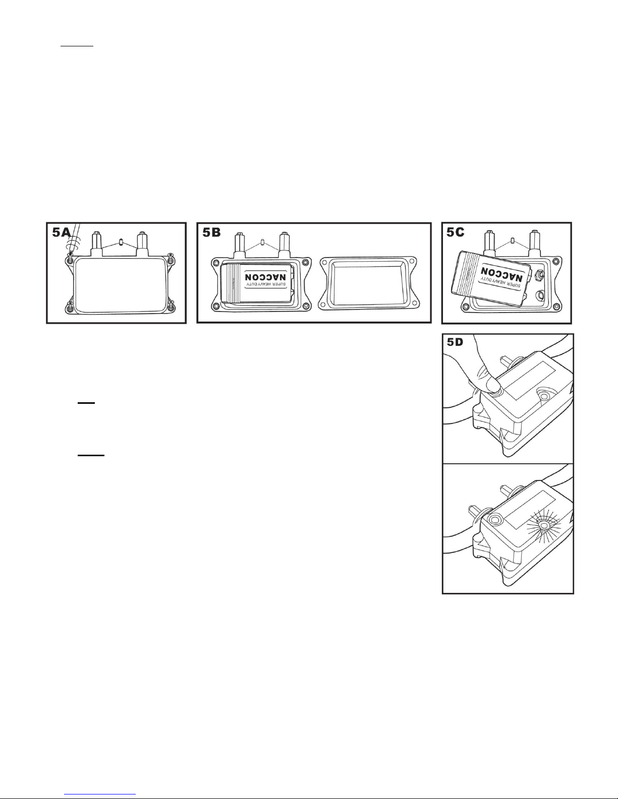
How to Replace the Battery
Note: Do not install the battery while the Receiver Collar is on your dog.
This Receiver Collar utilizes a replaceable battery. To replace the battery, use the screwdriver
provided to loosen the four screws (5A), open cover (5B), then you can see the 9V battery inside.
Insert a new 9V battery taking care to get the polarities correct (5C)and then replace the lid
carefully ensuring that the rubber sealing ring stays in place.
The collar’s default is ‘OFF’
1. ON: With the battery installed, press the Correction Level Button (5D)
for 3 seconds and release, TWO “Beeps” are sounded from the
receiver-collar which means the receiver is now on.
2. OFF: In the ON position. Press the Correction Level Button (5D) for
3 seconds and release, ONE “Beep” is sounded from the receiver and
means that the receiver-collar is now switched off.
To Set the Static Correction Level
CHOOSING THE MODE
Whether the receiver is ON or OFF you can choose the correction level
as that you want. However, when choosing the level when the receiver is
off, the receiver will default to this level when you turn it on.
Please read all steps before attempting to set the Static Correction
level.
1. The Receiver LED Indicator Light will emit a series of flashes representing the Static Correction
Level.
2. Increase the Static Correction Level by pressing and releasing the Correction Level Button
within 5 seconds of the previous series of flashes.
The Static Correction levels increase in strength from 1 to 5. Pushing the Correction Level Button
while the Receiver Collar is on level 5 will cause the Receiver Collar to revert to level 1. Refer to
the Function and Response Table to choose the Static Correction level that best fits your dog.
The Receiver Collar is equipped to automatically increase the level of Static Correction the longer
your dog remains in the Static Correction Zone if the collar is set at level 2 or above.

10
Function and Response Table
Indicator Light
Response
Static Correction
Level
Receiver Collar Function
Temperament of Dog
1 Flash
1
No Static Correction, Beep only
2 Flashes
2
Low Static Correction
Timid
3 Flashes
3
Medium Static Correction
Timid or Average
4 Flashes
4
Medium High Static Correction
Average or High Energy
5 Flashes
5
High Static Correction
High Energy
NOTE: Begin training with Static Correction Level 2 and only increase if your dog does not
respond to the Static Correction set.
Set the Boundary Width and Test the Receiver Collar
Step 6
The Boundary Control Switch on the side of the Fence Transmitter has three settings (6A).
Setting B is used for most properties.
For up to 400 metres of boundary please use setting B. For 400 to 750 metres please use setting
C. For over 750 metres please use setting A.
Use the Boundary Width Control knob to set the width of
the Warning Zone and Static Correction Zone (6B). Set
the Boundary Width as wide as possible to give your dog
the widest Warning and Static Correction Zones without
reducing the Dog Area too much.
Note: The Boundary Width Control knob does not
change the Static Correction level.
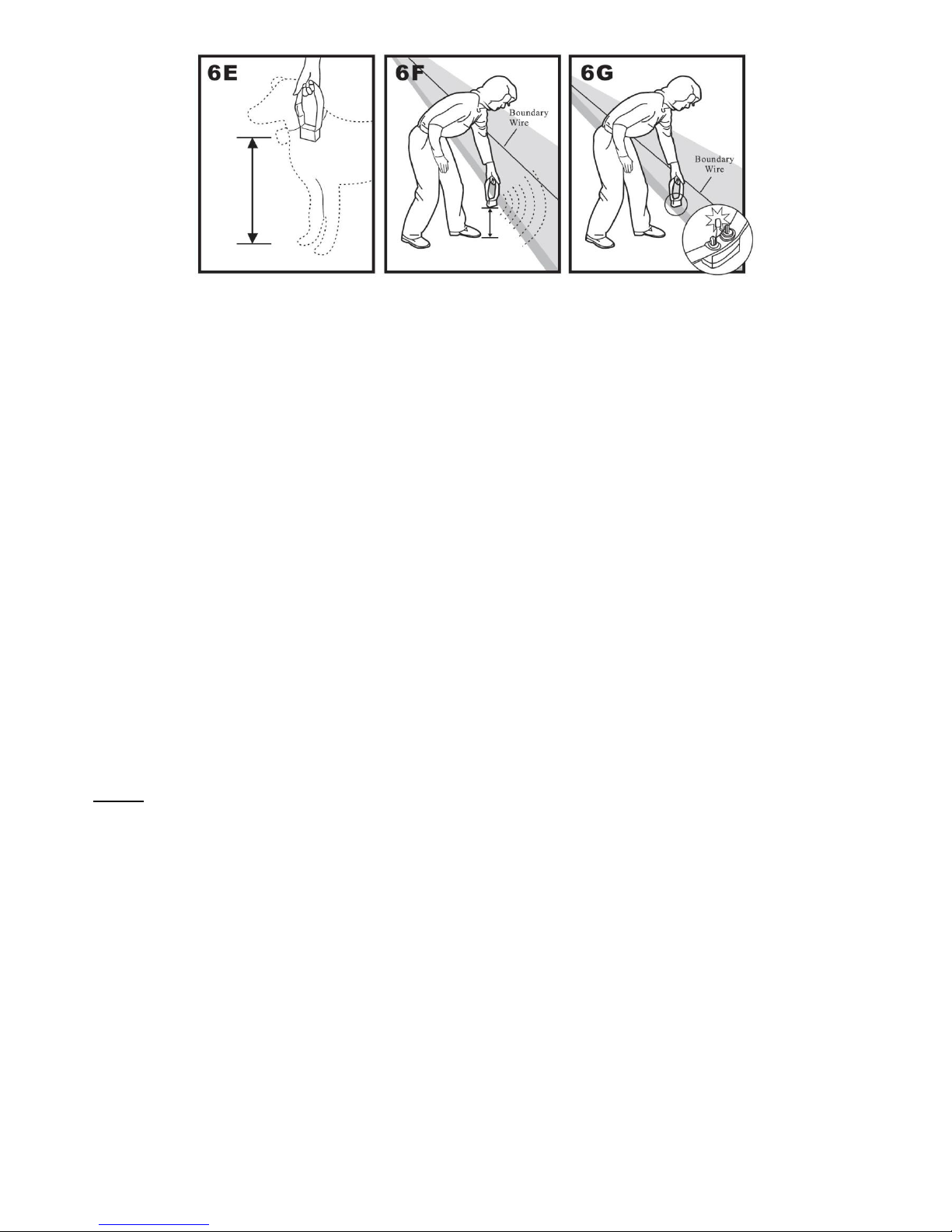
To identify the Warning and Static Correction Zones,
make sure the Receiver Collar battery is properly
installed, the Static Correction Level is set at 2 or above
and the Test Light is attached to the Contact Points (6C, 6D). Walk toward the Boundary Wire
with Contact Points pointing up and holding the Receiver Collar at your dog’s neck level (6E) until
the Receiver Collar beeps (6F).
Note: The Receiver Collar is waterproof, which can make the beep hard to hear.
11
If the Receiver Collar does not beep at the desired range, adjust the Boundary Width Control knob
to the desired setting. Turning the Boundary Width Control knob clockwise increases the
Boundary Width while turning it counter clockwise decreases it. Repeat this procedure as needed
until the Receiver Collar beeps at the desired distance from the Boundary Wire.
The numbers on the Boundary Width Control knob indicate signal strength and are not
representative of Boundary Width footage. If adjusting the Boundary Width Control knob does not
give the desired range, adjust the Boundary Control Switch to another setting to achieve your
desired range. If using a Double Loop, you may need to increase the separation of the Boundary
Wire to achieve the desired range.
The Receiver Collar beeps as a warning tone and ticks when delivering a Static Correction. After
hearing the beep, continue to walk towards the wire. The Receiver Collar should tick and the Test
Light should flash, indicating the Static Correction as you enter the Static Correction Zone (6G). A
warning beep and the flashing of the Test light indicate that the Receiver Collar and the system
are working properly and that you are ready to start burying the Boundary Wire. If the Receiver
Collar did not beep or the Test Light did not flash, refer to the “Troubleshooting” section.
Important: Remove the Test Light before placing the Receiver Collar on your dog.
Note: The Boundary Width is broken into 20% Warning Zone and 80% Static Correction Zone.
Install the Boundary Wire
Step 7 To Bury the Boundary Wire
Burying the Boundary Wire is recommended to protect it and prevent disabling the system.
1. Cut a trench 2 to 6cm deep along your planned boundary.
2. Place the Boundary Wire into the trench maintaining some slack to allow it to expand and
contract with temperature variations.
3. Use a blunt tool such as a wooden paint stick to push the Boundary Wire into the trench. Be
careful not to damage the Boundary Wire.
To attach the Boundary Wire to an existing fence
The Boundary Wire of the In-Ground Radio Fence can be attached to a chain link fence, split rail
fence, or a wooden privacy fence. The Boundary Wire can be attached as high as needed.
However, make sure the Boundary Width is set at a high enough range for the dog to receive the
signal. If using a Double Loop with an existing fence at least 1 metre tall, run the Boundary Wire
on top of the fence and return it on the bottom of the fence to get the 1 to 1.5 metre separation
needed.

12
Chain Link Fence (7A): Weave Boundary Wire through the links or use plastic quick ties.
Wooden Split Rail or Privacy Fence (7A): Use staples to attach Boundary Wire. Avoid
puncturing the insulation of the Boundary Wire.
Double Loop with an Existing Fence: Run Boundary Wire on top of the fence and return it
on the bottom of the fence to get the three to five foot separation needed.
Gate (Single Loop) (7B) Bury the Boundary Wire in the ground across the gate opening.
Note: The signal is still active across the gate. Your dog cannot pass through an open gate
Gate (Double Loop) (7B): Bury both Boundary Wires across the gate opening while keeping
them 1 to 1.5 metres apart.
To Cross Hard Surfaces
(driveways, sidewalks, etc.)
Concrete Driveway
or Sidewalk (7D):
Place the Boundary
Wire in a
convenient
expansion joint or
create a groove
using a circular saw
and masonry blade.
Place the Boundary
Wire in the groove
and cover with an
appropriate
patching compound.
(a bead of silicone
is ideal) For best
results, brush away
dirt or other debris
before patching.
Gravel or Dirt Driveway (7E): Place the Boundary Wire in a PVC pipe or water hose to
protect the Boundary Wire before burying.

13
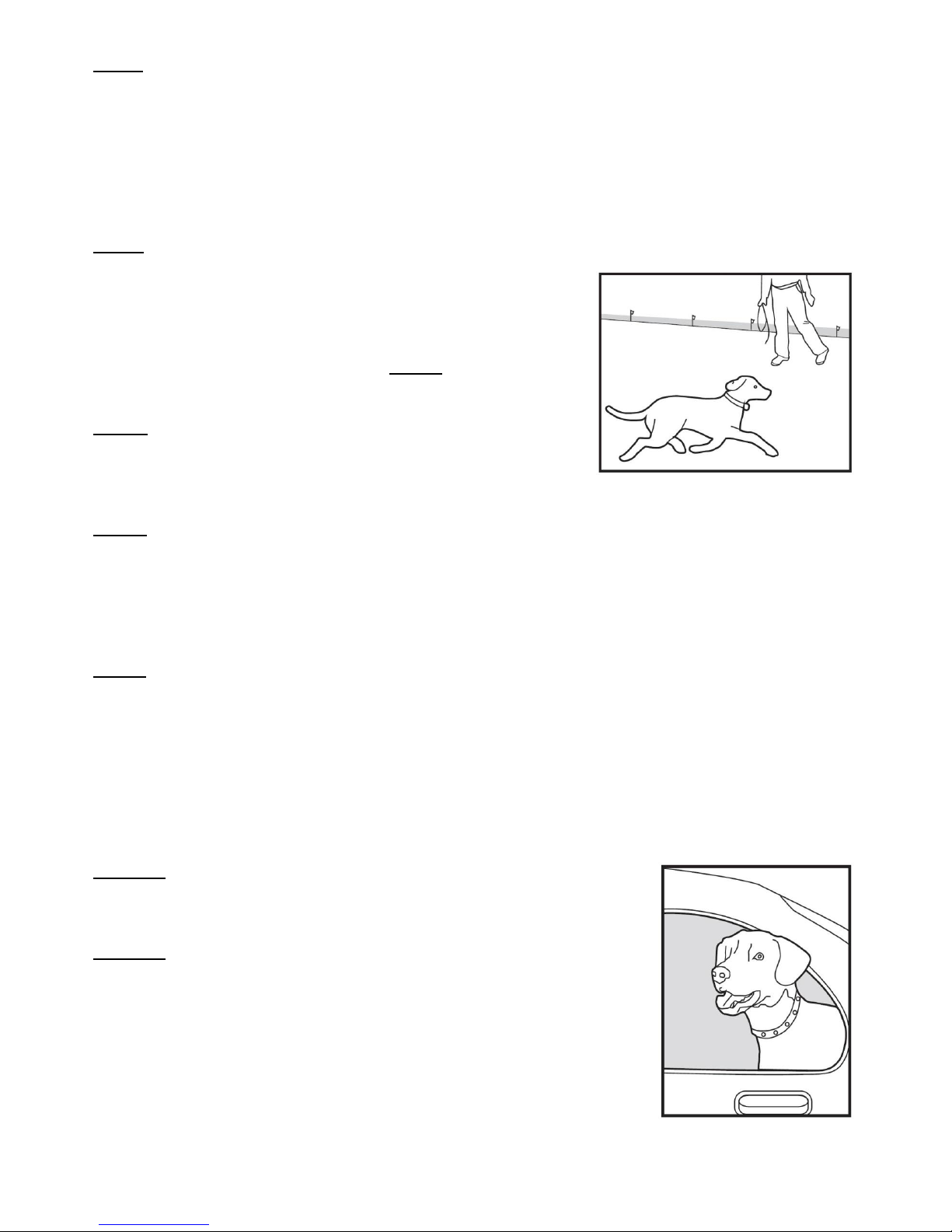
Place the Boundary Flags
Step 8 During training the Boundary Flags are visual
reminders for your dog of where the Warning Zone is
located.
1. Hold the Receiver Collar at your dog’s neck
height.
2. Walk towards the Warning Zone until the
Receiver Collar beeps (8A).
3. Place a Boundary Flag in the ground (8B).
4. Walk back into the Dog Area until the beeping stops.
5. Repeat this process around the Warning Zone until it is marked with Boundary Flags every 10
feet. Note: If you cannot hear the beep, see the Test Light Instructions in Step 6.
Step 9 Fit the Receiver Collar. The proper fit and placement of your Receiver Collar is
important for effective training. The Contact Points must have direct
contact with your dog’s skin on the underside of its neck.
To assure a proper fit, please follow these steps:
1. Make sure that the battery is not installed in the Receiver Collar.
2. Start with your dog standing comfortably (9A).
3. Centre the Contact Points underneath your dog’s neck, touching the skin.
If your dog has a long or thick coat, use the enclosed long
Contact Points to reach through the hair.
Note: It is sometimes necessary to trim the hair around the
Contact Points to make sure that contact is consistent.
4. Check the tightness of the Receiver Collar by inserting one
finger between the end of a Contact Point and your dog’s neck.
The fit should be snug but not constricting (9B).
5. Allow your dog to wear the collar for several minutes then
recheck the fit. Check the fit again as your dog becomes more
comfortable with the Receiver Collar.
6. Trim the collar as follows: (9C):
a) Mark the desired length of the Receiver Collar with a pen.
Allow for growth if your dog is young or grows a thick winter
coat.
b) Remove the Receiver Collar from your dog and cut off the excess.
c) Before placing the Receiver Collar back onto your dog, seal the edge of the cut collar by
applying a flame along the flayed edge.
IMPORTANT: For comfort, safety and effectiveness of product, please ensure the following:
During the first 2 weeks of training do not use the training device on your dog without your
direct supervision.
Check the fit to prevent excessive pressure by being able to insert one finger between the
Contact Point and your dog’s skin.
Your dog must be carefully examined daily for any signs of a rash or sore.
If a rash or sore is observed, discontinue the use of the Receiver Collar for a few days.
If the condition persists beyond 48 hours, see your veterinarian.
Your dog’s neck and the Contact Points must be washed weekly with a wash cloth and mild
hand soap, then rinsed thoroughly.
NB: A condition called Pressure Necrosis, which is a devitalisation of the skin due to excessive
and prolonged contact against the Contact Points, may occur if the steps above are not
followed.

14
TRAINING GUIDE
IMPORTANT: Be Patient with your Dog
Proper training of your dog is essential to the success of the In-Ground Radio Fence. Read this
section completely before beginning to train your dog. Remember that the In-Ground Radio Fence
is not a solid barrier.
Have fun with your dog throughout the training process. Training should be fun, fair, firm and
consistent.
Train for 10 to 15 minutes at a time. Don’t try to do too much too quickly. More frequent short
sessions are better than less frequent longer sessions.
If your dog shows signs of stress, slow down the training schedule, add additional days of
training, or increase the amount of play time with your dog in the Dog Area. Common stress
signals include:
Dog pulling on leash toward the house
Ears tucked
Tail down
Body lowered
Nervous/frantic movement or stiffening of dog’s body
Your dog must be completely comfortable near the Boundary Flags at the end of every training
session. Spend at least 5 minutes of “play time” at the completion of each session within 10
feet of the Boundary Flags.
Finish each training session on a positive note with lots of praise and play.
Remove the Receiver Collar after each training session.
Be sure to contain your dog by another means during the training period (e.g. pen, tie-out,
leash, etc.).
During training, if you need to take your dog out of the Dog Area, remove the Receiver Collar
and either pick your dog up or put him in the car to pass out of the Dog Area.
Even if you think your dog is responding well to the training, complete the entire training.
Reinforcement is important!
Step 1 Day 1 –Boundary Flag Awareness
Perform three sessions on day 1, each training session lasting 10-15 minutes.
Goal:To have your dog learn that the Boundary Flags and warning beep from the Receiver Collar
define the new Dog Area.
Setup:
Programme the Receiver Collar to level #2 or #3 depending on the size and temperament of
your dog.
Put a separate non-metallic collar on your dog’s neck ABOVE the Receiver Collar and attach a
leash. Note: Be sure the extra collar does not put pressure on the Contact Points
Have tiny pieces of treats available that your dog will find desirable
Have your dog’s favourite play toy available.
Steps:
1. Begin by walking your dog on a leash in the Dog Area. Calmly praise and talk to your dog,
occasionally giving treats.
2. Move toward the Boundary Flags (10A). Keep your mood happy and throw treats to the
ground.
3. With full control of your dog on a leash, toss a treat on the outside edge of the flags. As your
dog enters the Static Correction Zone to receive the treat, he will begin to receive a mild Static
Correction ((10B). The longer your dog remains in the Static Correction Zone, the stronger the
Static Correction will get. Allow him to stay in the Static Correction Zone for 2 seconds, then
gently help your dog back into the Dog Area (10C). Immediately praise and offer him a treat as

15
he enters the Dog Area, even if you have helped with the leash. Wiggle a Boundary Flat to
help your dog understand that the discomfort of the Static Correction happens around the
flags.
4. Repeat this process at several different Boundary Flags. Your dog should start to resist going
after the treat in the Static Correction Zone. If your dog continues to enter the Static Correction
Zone, check the fit of his Receiver Collar and allow him 2-3 seconds in the zone before pulling
him back to the Dog Area.
Note: Never
allow your dog to eat the treat in the Static Correction Zone
Step 2 Days 2 thr 4 –Continue Boundary Flag Awareness
Perform three sessions per day, each lasting 10-15 minutes. Goal: To train your dog to stay in the
Dog Area and respect the boundary while you are outside of it.
Setup:
Programme the Receiver Collar to level #3 or #4 depending on the size and temperament of
your dog.
Put a separate non-metallic collar on your dog’s neck ABOVE the Receiver Collar and attach
leash. Note: Be sure the extra collar does not put pressure on the Contact Points.
Have tiny pieces of treats available.
Have your dog’s favourite play toy available.
Steps:
1. Repeat steps 1-4 in Phase One.
2. Drop the leash, leaving your dog in the Dog Area.
3. Walk outside the boundary and wiggle the Boundary Flags facing your dog.
4. Continue around the entire boundary doing this, tossing treats to your dog in the Dog Area and
praising him.
Step 3 Days 5 thru 8 –Distraction Phase. Perform three training sessions per day, each lasting
10 to 15 minutes. Goal: To train your dog to stay within the Dog Area with distractions outside of
the Dog Area.
Setup:
Programme the Receiver Collar to level #3 or #4 depending on the size and temperament of
your dog.
Put a separate non-metallic collar on your dog’s neck ABOVE the Receiver Collar and attach a
leash. Note: Be sure the extra collar does not ;put pressure on the Contact Points
Have tiny pieces of treats available.
Have your dog’s favourite play toy available.
Create distractions to tempt your dog to enter the Warning and Static Correction Zones:
Have a family member cross from inside the Dog Area to outside of it.
Throw a ball outside of the Dog Area.
Have a neighbour walk their dog outside of the Dog Area.
16
Steps:
1. With full control of your dog on a leash, have the distraction presented.
2. If your dog does not move toward the distraction, praise and offer a treat.
3. If your dog does react to the distraction, allow him to go into the Static Correction Zone.
4. Help your dog back into the Dog Area if he does not turn back after 3 seconds.
5. Treat and praise your dog anytime he comes back into the Dog Area with or without help.
6. Repeat this process with other distractions. Use other family members during this process.
Step 4 Days 9 thru 14 –Unleashed Supervision
Training sessions should start at 10-15 minutes, gradually
increasing to over an hour. Your dog is ready for this step only
when he clearly avoids the entire Boundary Flag line,
regardless of any distractions or temptations. During this step,
do not leave your dog unattended. Goal: To give your dog
free run of the Dog Area off the leash.
Setup:
Adjust the Receiver Collar to the permanent setting
appropriate for your dog depending on his size and
temperament.
Steps:
1. Enter the Dog Area with your dog wearing the Receiver Collar.
2. Walk around the yard and play with your dog, staying within the Dog Area at all times.
3. Preoccupy yourself with another task in the yard while watching your dog.
4. Should your dog escape, take the Receiver Collar off or turn the fence system off at the Fence
Transmitter and lead him back into the Dog Area.
Step 5 Days 14 thru 30 –Dog Monitoring
Your dog is ready to run! Check in on your dog at regular intervals.
Note: After you are satisfied your dog’s training is complete, remove every other Boundary Flag
every 4 days until all flags are removed. Save Boundary Flags for future use.
Taking Your Dog Out of the Dog Area
Important: Remove the Receiver Collar and leave it in the Dog Area.
Once your dog learns the Boundary Zone, he will be reluctant to cross it for walks or car rides.
Option 1: Replace the Receiver Collar with a regular collar. Put your
dog in a car that is within the Dog Area and drive him out of the Dog
Area.
Option 2: Replace the Receiver Collar with a regular collar and leash.
Walk your dog out of the Dog Area while giving a command such as
“Ok” at a specific place of the Boundary Zone (the end of your
driveway, sidewalk, etc.). Always leave the Dog Area with a leash at
this place and your dog will associate leaving the Dog Area only on a
leash, only at this place, and only with a person. You may initially
need to convince your dog to leave the Dog Area with a food treat and
lots of praise. Note: You may also carry your dog out of the
Dog Area.
Congratulations! You have now successfully completed the training programme.

17
TROUBLESHOOTING
Receiver Collar is not beeping or
correcting.
Check battery to make sure it is installed properly.
Check that both lights are lit on the Fence Transmitter.
If not, perform the “Short Loop Test”.
The Receiver Collar is beeping, but
the dog is not responding to the
Static Correction.
Make sure the Static Correction Level is set at 2 or above.
Test the Receiver Collar with the Test Light.
If the Test Light flashes, check the fit of the Receiver Collar.
Trim your dog’s fur where the Contact Points touch the neck and/or
switch to the longer Contact Points.
Increase the Static Correction Level.
Repeat training steps to reinforce training.
The Receiver Collar has to be held
on top of the Boundary Wire to
activate.
Replace the battery.
Adjust Boundary Width Control knob clockwise to increase the distance
from the Boundary Wire that the Receiver Collar activates.
Adjust the Boundary Control Switch to another setting.
If using a Double Loop, make sure Boundary Wires are 1 to 1.5 metres
apart.
If the Receiver Collar still has to be held on top of the Boundary Wire,
perform the “Short Loop Test”.
The Receiver Collar activates
inside the house.
Turn the Boundary Width Control knob counter clockwise to decrease
the distance from the Boundary Wire that the Receiver Collar activates.
Make sure the Boundary Wire is not running too close to the house.
The signal can transmit through the walls of your house.
Make sure Boundary Wires are twisted from Boundary to the Fence
Transmitter.
I have an inconsistent signal.
Make sure that the Fence Transmitter is at least 1 metre from any large
metal objects or appliances.
Make sure all Boundary Wire turns are gradual.
Make sure the Boundary Wire is not running parallel to and within 1.5
metres of electrical wires, neighbouring containment systems, telephone
wires, television or antenna cables, or satellite dishes.
The Power and Loop Indicator
Lights are off.
Check that the Power Adapter is plugged into the Fence Transmitter.
Try plugging into another 240 volt outlet.
Remove the fuse door on the back of the Fence Transmitter and change
the fuse with the spare one supplied.
If the lights still do not come on, the Fence Transmitter and/or Power
Adapter needs to be replaced.
The Power Light is on, the Loop
Indicator Light is off, and the Fence
Transmitter loop alarm is sounding.
Make sure both ends of the Boundary Wire are plugged into Boundary
Wire Terminals and that 1cm of the insulation is stripped so that the
copper wire is exposed.
Perform the “Short Loop Test” to determine if the Fence Transmitter
needs to be replaced or if the Boundary Wire is broken.
If the Fence Transmitter is functioning properly, you have a break in
your Boundary Wire. See the “Locating a Break in the Wire” section in
this guide.
The fuse blows when it is replaced.
The Fence Transmitter and/or Power Adapter needs to be replaced.

18
Additional Information
The Boundary Wire is buried so that it is not accidentally tripped over or cut. Use care when
using a weed eater or when digging near the Boundary Wire to prevent damage.
The system should only be used with healthy dogs. Contact your veterinarian if you have
concerns about the medical condition of your dog (medication, pregnant, heart conditions,
etc.).
This system is not for vicious or aggressive dogs. If your dog may pose a threat to others, DO
NOT USE THIS SYSTEM. If you are unsure if your dog is aggressive, please consult your
veterinarian or a certified trainer.
The In-Ground Radio Fence is for residential use only.
The Static Correction will get your dog’s attention, but will not cause harm. It is designed to
startle, not to punish.
Test the Receiver Collar every 3 to 6 months. Battery life depends upon how often the
Receiver Collar is activated.
Short Loop Test
The Short Loop Test is a simple test to determine if each component (Fence Transmitter, Receiver
Collar and Boundary Wire) is functioning properly.
1. Disconnect the Boundary Wire and Ground Wire.
2. Cut approximately 4 metres of unused Boundary Wire and connect it to the Boundary Wire
Terminals in a loop.
3. Attach the Test Light to the Receiver Collar.
4. Spread the Boundary Wire out into a circle. Set the Boundary Control Switch to B.
5. Set the Boundary Width Control knob to 10 and the Static Correction Level to level 2 or above.
6. If the Loop Indicator Light is not lit, then your Fence Transmitter is not functioning properly.
7. If the Loop Indicator Light is lit, disconnect one end of the Boundary Wire from the Boundary
Wire terminal.
8. If the loop alarm does not sound, the Fence Transmitter needs to be replaced.
9. If the loop alarm does sound, plug the Boundary Wire back into the Boundary Wire Terminal.
10.Hold the Receiver Collar next to the 10-foot length of Boundary Wire. The Receiver Collar
should beep about one foot away from the Boundary Wire. The Test Light should then flash as
you hold the Receiver Collar closer to the Boundary Wire.
11.If Receiver Collar does not beep and the Test Light does not flash, try to replace the battery in
the Receiver Collar.
12.If the Receiver Collar beeps, there may be a complete or partial break in the Boundary Wire.
See the “To Locate a Break in the Boundary Wire” section below.
To Locate a Break in the Boundary Wire
Please follow these steps in determining where you have a break in your Boundary Wire:
1. Locate your original splice(s) and verify they have a good solid connection.
2. Check your yard to determine any possible damage to the Boundary Wire (e.g. recent digging,
aerating, rodent burrowing, or any other noticeable disturbance in your yard next to the
Boundary Wire.
If you still cannot find the break in the Boundary Wire, there is an option for locating it:
Option: Follow the procedure below:
1. Unplug the Fence Transmitter.
2. Connect both ends of your twisted Boundary Wire to one Boundary Wire Terminal.
3. Measure and cut a Test Wire which is half the length of your total Boundary Wire footage.
4. Connect one end of the Test Wire to the other Boundary Wire Terminal.
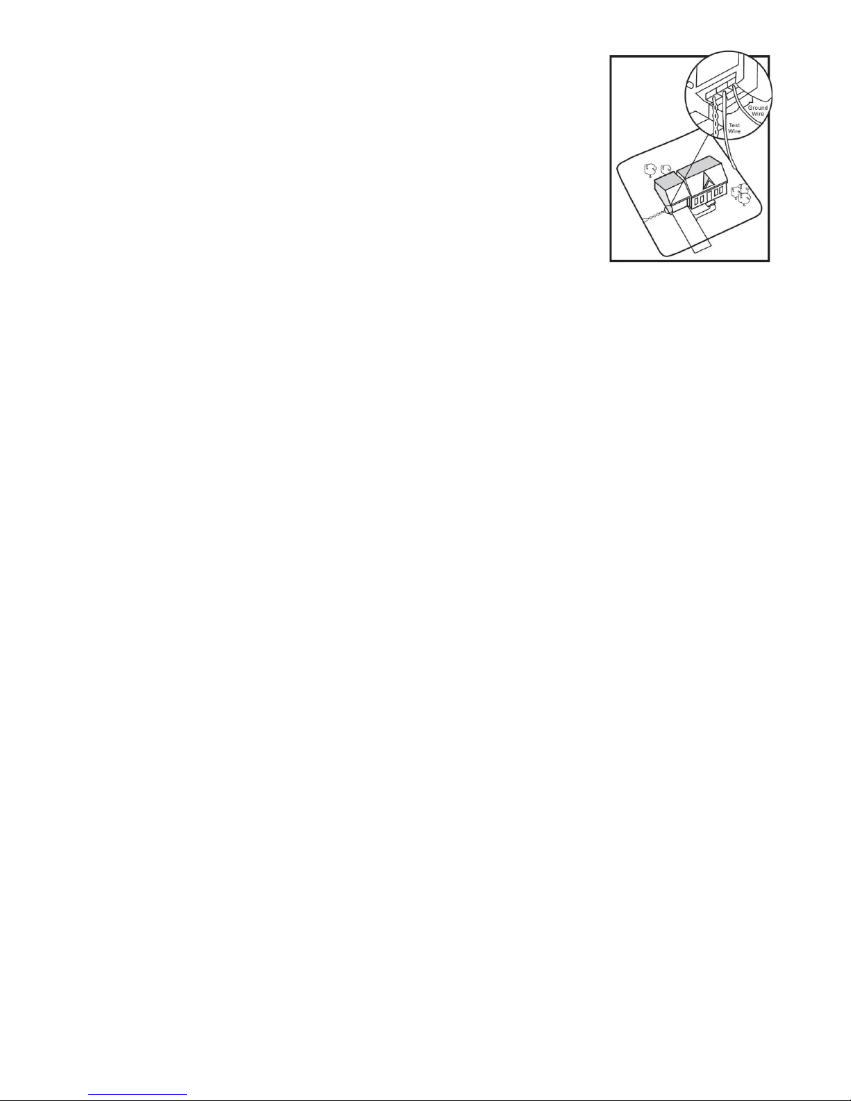
19
5. Locate the halfway point of your boundary and cut the Boundary
Wire.
6. Splice the other end of the Test Wire to either side of your Boundary
Wire where you cut it in half.
7. Plug in the Fence Transmitter and check the Loop Indicator light. If
the Loop Indicator Light is on you can assume the break is in the
other half of the Boundary Wire.
8. If the Loop Indicator Light did not come on, you may assume there is
a break in this portion of the Boundary Wire. However, there is a
small chance of having more than one break in your system. Be sure
to check both halves of your entire loop.
9. Replace the damaged Boundary Wire with new Boundary Wire.
10.Reconnect the Boundary Wire to the Fence Transmitter.
11.Check the Loop Indicator Light. If the Loop Indicator Light is on, test the system with the
Receiver Collar.
Terms of Use and Limitation of Liability
1. Terms of Use
This Product is offered to you conditional upon your acceptance without modification of the
terms, conditions and notices contained herein. Usage of this Product implies acceptance of
all such terms, conditions, and notices.
2. Proper Use
This Product is designed for use with dogs where training is desired. The specific
temperament of your dog may not work with this Product. We recommend that you not use
this Product if your dog is less than 7Kg or if your dog is aggressive. If you are unsure
whether this is appropriate for your dog, please consult your veterinarian or certified trainer.
Proper use includes reviewing the entire Guide provided with your Product and any specific
Caution Statements.
3. No Unlawful or Prohibited Use
This Product is designed for use with dogs only. This dog training device is not intended to
harm, injure or provoke.
4. Limited of Liability
In no event shall Machines Gadgets and Gizmows Ltd be liable for any direct, indirect,
punitive, incidental, special or consequential damages, or any damages whatsoever arising
out of or connected with the use or misuse of this Product. Buyer assumes all risks and
liability from the use of this Product.
5. Modification of Terms and Conditions
Machines Gadgets and Gizmows Ltd reserves the right to change the terms, conditions and
notices under which this Product is offered.
CAUTION
The In-Ground Radio Fence is NOT a solid barrier. The system is designed to act as a deterrent
to remind dogs by electric stimulation to remain in the boundary established. It is important that
you reinforce training with your dog on a regular basis. Since the tolerance level to static
electrical stimulation varies from dog to dog, Machines Gadgets and Gizmows Ltd CANNOT
guarantee that the system will in all cases, keep a dog within the established boundary. Not all
dogs can be trained to avoid crossing the boundary! Therefore, if you have reason to believe that
your dog may pose a danger to others or harm itself if it is not kept from crossing the boundaries,
you should NOT rely solely upon the In-Ground Radio Fence to confine your dog. Machines
Gadgets and Gizmows Ltd shall NOT BE LIABLE for any property damage, economic loss or any
consequential damages, sustained as a result of any animal crossing the boundary.

20
Made in China for Machines Gadgets and Gizmows Ltd., PO Box 592, Kerikeri New Zealand
Website: www.MGG.co.nz Email: [email protected]
Table of contents
Other MGG Pet Care Product manuals


