MGG Maxi User manual


2
© MGG Products New Zealand 2021
Index Page Number
Contents 3
Additional items you may need 3
Key-terms 3
Suitable for 4
How the system works 4
Warranty 4
Operating Guide
STEP 1: Positioning the transmitter 5
STEP 2: Laying out the system 5
STEP 3: Layout the proposed boundary-wire 7
STEP 4: Connecting the boundary-wire to the transmitter 8
STEP 5: Preparing the collar-receiver 9
STEP 6: Setting the boundary width & testing the Collar-receiver 10
STEP 7: Installing the boundary wire 11
STEP 8: Placing the boundary training flags 12
STEP 9: Fitting the collar-receiver 12
Step 10: Training Guide 13
Trouble-shooting 17
Short loop test 18
Locating a break in the wire 18
Terms of use and limitation of liability 19
Caution 19
MGG offer a return-to-base warranty for 12 months against faulty manufacture
Please retain your original invoice for warranty purposes

3
© MGG Products New Zealand 2021
Contents
A standard system will contain the following:
•1 x transmitter
•1 x 12v mains adaptor
•1 x collar-receiver unit
•1 x collar strap
•1 set each of long & short prongs (contact-points)
•1 x collar-receiver test light
•1 x 5v USB mains adaptor
•200m boundary-wire
•6 x waterproof heat-shrink joiners
•1 x set of boundary training flags
•Instruction manual
You may have ordered additional wire or collar-receivers, please check these against your invoice
Additional items you may need
•Tape measure
•Drill & mounting hardware
•Flat-edged spade or lawn edger
•Pliers
•Wire stripping pliers
•Scissors
•Lighter
•Electrical tape
•Additional MGG waterproof heat-shrink joiners
•Cable ties
•Ground rod & clamp
•Waterproofing compound (e.g. silicone caulk)
•Length of hosepipe if crossing a driveway
Key-words
Transmitter - the device that transmits the radio-signal through the boundary wire
Dog containment area - the area within the containment boundary where your dog can roam
freely
Static-correction zone - the area where your dog’s collar-receiver will emit a beep & static
correction as signals to return the dog to the dog containment area
Boundary-width - the distance between the start of the static-correction zone and the boundary
Collar-receiver - the device that receives the radio-signal from the boundary wire
Prongs (contact-points) - the metal prongs which screw onto the collar-receiver. These are the
contact-points through which the collar-receiver delivers the safe static-correction when your dog
moves into the static-correction zone
Power-input socket - this connects the 12v mains adaptor into the transmitter
Boundary-control switch –located on the side of the transmitter, this switch has three options to
select the length of boundary-wire being used
Ground terminal - the terminal where the ground wire connects to the transmitter
Boundary-wire terminals - the terminals where the boundary-wires connect to the transmitter in
order to complete a continuous loop
Loop indicator light –this light indicates that the boundary-wire makes a complete loop which
enables the signal to be transmitted. This will illuminate to indicate the system is working
Boundary-width control - an adjustable knob on the front of the transmitter which adjusts the
width of the static correction zone. It does not adjust the level of static-correction delivered by the
collar-receiver

4
© MGG Products New Zealand 2021
The MGG Maxi Dog Containment System is suitable for:
•All breeds of dog over 7kgs in weight
•The system should only be used with healthy dogs
•Contact your veterinarian if you have concerns about the medical condition of your dog
(medication, pregnant, heart conditions etc) prior to purchasing any dog containment system
•This system is for residential use only
•The static-correction will get your dog’s attention but will not cause harm. It is designed to
startle, not to punish
•This system is NOT suitable for aggressive dogs. If your dog poses a threat to others, DO NOT
USE THIS SYSTEM. If you are unsure if your dog is aggressive, please consult your
veterinarian or a certified dog trainer prior to purchasing any containment system
How the System Works
The MGG Maxi Dog Containment System has been proven safe, comfortable and effective for all
breeds of dog over 7kgs in weight. The system works by producing a radio-signal from the
transmitter which is sent through the boundary-wire (effective for up to 1000 metres of boundary-
wire). The dog containment area is created by the boundary-wire which can be buried or attached
to a fixed object such as an existing fence. Where there is no visual boundary for your dog, such
as a fence or hedge, you can initially define the dog containment area with the boundary training
flags to act as a visual aid during your dog’s training period. When dog containment is required,
your dog will wear the collar-receiver with the prongs making direct contact with the skin of the
neck. Once trained in the dog containment area and aware of the static-correction zone, your dog
can then roam freely within the designated dog containment area. If your dog reaches the static-
correction zone, the collar-receiver will issue a beep and a safe static-correction will be delivered
through the prongs (contact-points), diverting their attention to return to the designated dog
containment area.
Warranty
The MGG Maxi Dog Containment System comes with a 12-month limited warranty as specified on
our website mggproducts.co.nz/terms-conditions.
Events which ARE COVERED under the warranty
1. Any defect or damage which is a result of the manufacturing process
2. If the product ceases to function during the warranty period which is not the result of improper
use or damage
Events which are NOT COVERED under the warranty
1. This instruction manual is designed to minimise damage and faults arising as a consequence of
inappropriate set-up or use of the product
IMPORTANT: please read this instruction manual carefully BEFORE set-up
2. Damage caused by wear and tear
3. Damage caused by improper use or lack of maintenance
4. Any situation where the product is not able to be returned to MGG Products for a technicians
inspection
5. Product failure due to incorrect set-up or overcharging of the collar-receiver beyond the time-
limit specified in this manual
5
© MGG Products New Zealand 2021
OPERATING GUIDE
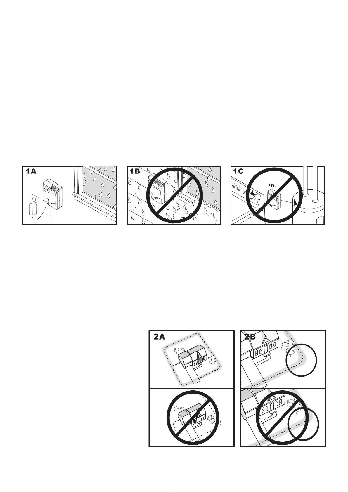
STEP 1: Positioning the Transmitter
The transmitter must be placed as follows:
•In a dry, well-ventilated and protected area (1A, 1B)
•In an area where temperatures do not fall below freezing (e.g. garage, basement, shed, closet)
•Secured to a stationary surface using appropriate mounting hardware (not included)
•At least 1-metre from large metal objects or electrical appliances which may interfere with the
consistency of the radio-signal (1C)
•In a place where the boundary-wire can exit the building. This can be accomplished through a
4mm hole drilled through the wall or a window or door frame. Ensure the drill path is clear of
any utilities. Check to make certain the boundary-wire is not cut off, pinched by a window, door
or garage door which overtime, will cause damage to the system
To prevent fires and electrical hazards, install the transmitter in buildings that are in accordance
with national and local electrical safety standards.
STEP 2: Basic tips for planning the layout for the Dog Containment Area
It is recommended that you read this entire manual BEFORE planning the design of your dog’s
containment area. This will save time and avoid unnecessary changes.
•Design a layout that is suitable for your yard. Sample layouts are provided in this section
•The boundary-wire MUST START at the transmitter & make a continuous loop back to it (2A)
•Always use gradual turns at the corners to produce a more consistent boundary (2B).
DO NOT use sharp turns which will cause gaps in the boundary of the dog containment area
•Avoid making passageways which are too narrow for your dog to move about freely, for
example, along the sides of a house
Caution:
The boundary-wire must be laid at
least 2 metres from the walls of the
house. This is because electrical
cables in the walls can pick-up the
radio-signal and redistribute it via all
electrical cables in your house, garden
or shed. The same rule applies to
laying the boundary-wire within 2
metres of other out-buildings where
there are electrical cables in the wall
structure.
The collar-receiver must be removed
when your dog is inside the house.
This may require you to consider an
alternative layout. See sample layouts on page 6

6
© MGG Products New Zealand 2021
Sample Layouts
Sample 1 - Single perimeter loop (2C & 2D)
The most common layout which allows your dog to roam safely and freely within the designated
dog containment area of your property (2C). It can also be used to protect gardens, pools &
landscaping (2D).
Sample 2 - Single perimeter loop using existing fence (2E)
This layout allows you to include your existing fence as part of your layout. It prevents your dog
from jumping over or digging under the existing fence. It reduces the amount of wire needed to be
buried.
From the transmitter, run the wire to A, A to B, B to C, C to D, D
to E, E to A, twist the wires from Aback to the transmitter.
See ‘Install the boundary-wire’section for further details
regarding attaching the boundary-wire to a fence.
Sample 3 - Double loop
If you are NOT establishing the boundary zone on all sides of your property (as in samples 1 & 2),
a double loop MUST BE USED.
Caution:
When using a double loop, the boundary-wire MUST BE SEPERATED by a minimum of 1 to 1.5
metres. This avoids cancelling the signal
Note: A Double loop requires twice as much wire
Sample 4 - Front boundary only (double loop) 2F
From the transmitter, run the wire to A, A to B, B back to A
keeping the wire separated by at least 1 to 1.5 metres.
Twist the wire from Aback to the transmitter.
2F

7
© MGG Products New Zealand 2021
STEP 3: Layout the proposed boundary-wire
BEFORE burying the boundary-wire or attaching it to an existing fence, lay out the proposed dog
containment area and TEST the system first. This will minimise inadvertent problems and make
any necessary changes to the layout much easier.
Caution:
Running the boundary-wire parallel to and within 1.5 metres of electrical wires, neighbouring
containment systems, telephone wires, satellite dishes, televisions or antenna cables will cause an
inconsistent signal. If you must cross any of these, do so at a 90° angle (i.e. perpendicular)
Areas where the signal needs to be cancelled
Twisting the ‘out-going’ and ‘in-coming’ boundary wire together cancels the signal and allows your
dog to cross over that area safely. In addition, twisting the boundary-wire from the transmitter to
the starting point of the designated dog containment area will cancel the signal and minimise any
inadvertent issues associated with electrical wires in the wall or other nearby household
appliances. Containing the boundary-wire in plastic or metal piping will not cancel the signal.
Twist the boundary-wire 8 to 10 times per 30cms to cancel the signal.
Splicing or repairing the boundary-wire using the MGG waterproof heatshrink joiners
If additional boundary-wire is required to extend the wire loop, you will need to splice the wires
together. Strip away approximately 3-4mm of insulation from the ends of the boundary-wires to be
spliced. Make sure the exposed copper boundary-wire is not corroded. If the wire is corroded, cut
it back further to expose clean copper wire. Insert the stripped ends into the MGG waterproof,
heatshrink joiners supplied with the system. Crimp the centre of the joiner together firmly with a
pair of pliers. Once crimped, use the heat of a flame from a lighter (to avoid burning do not touch
the joner with the flame itself) to activate the shrinkage process. This will create a strong,
waterproof join.
Useful tip: Any future breaks in the boundary-wire tend to be at the splicing joints. It is
recommended that you make a sketch of the dog containment area and the position of the
boundary-wire, noting where any splicing has been made.
Additional boundary-wire
We recommend the use of MGG’s genuine UV-inhibitor treated boundary-wire as supplied with
this MGG Maxi Dog Containment System. This can be used for direct burial or attachment of the
wire to an existing fence. Extra MGG 2.4mm boundary-wire can be purchased at
www.mggproducts.co.nz
Note: When adding boundary-wire, it must still act as a continuous loop. Waterproof heatshrink
joiners must be used.
The length of boundary-wire required is dependent on the amount of twisted wire required, the
shape of the layout and single or double loop systems. Approximate lengths are as follows:
Acreage
Length of boundary-wire
required (approx.)
1/4 acre
1/3 acre
1/2 acre
1 acre
2 acres
5 acres
10 acres
130m
150m
185m
260m
370m
580m
880m
8
© MGG Products New Zealand 2021
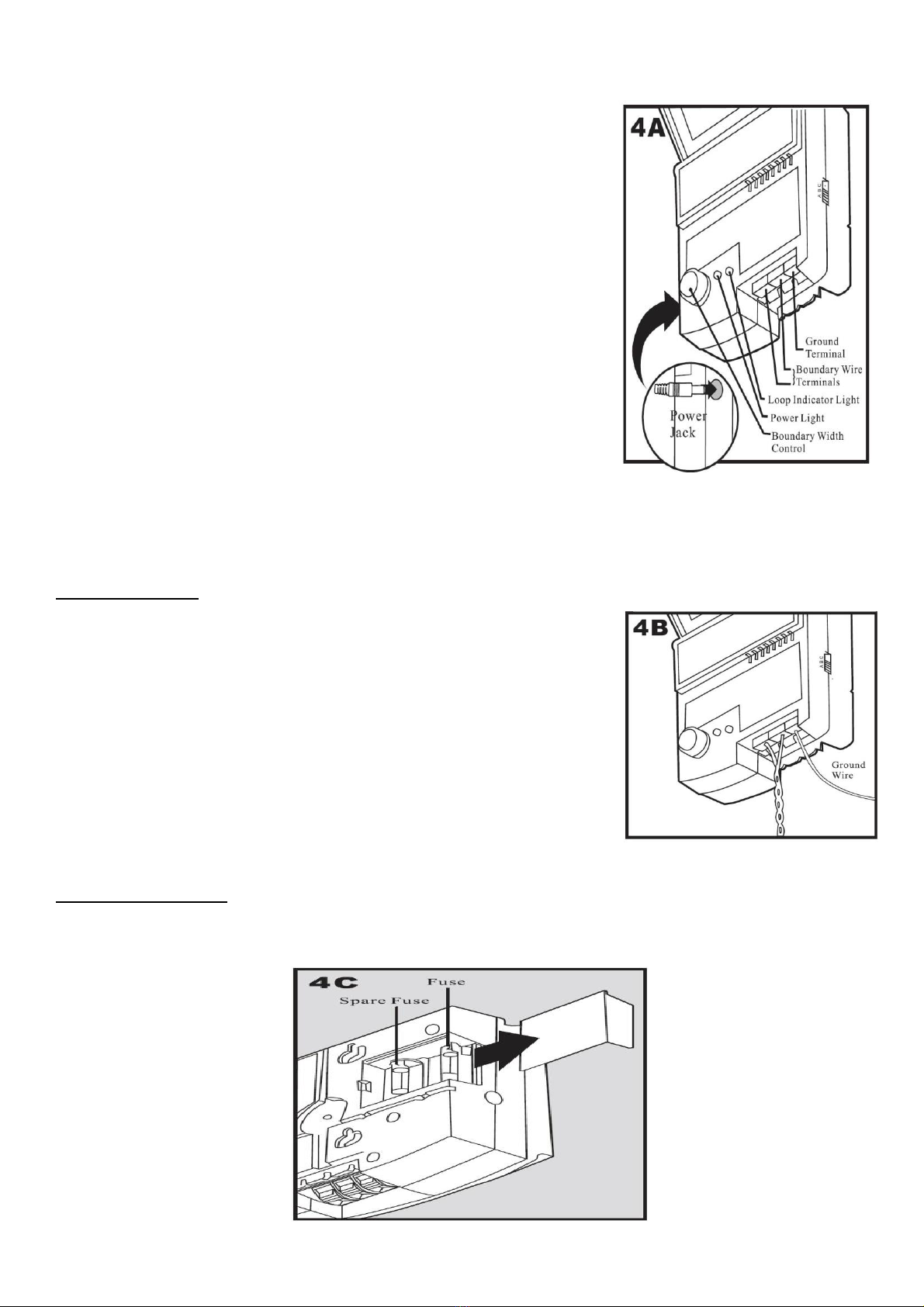
STEP 4: Connecting boundary-wire to the transmitter (4A)
•Run the boundary-wire to the transmitter. This may require
drilling a hole through a wall, window frame or beneath a door
•The boundary-wires need to be twisted together to cancel
signals occurring from other electrical sources (see page 7)
•Strip the ends of the boundary-wire by approximately 1cm and
insert directly into the RED boundary-wire terminals of the
transmitter (4A)
When the entire system set-up is complete
•Ensure the boundary-width is set as per STEP 6 page 10
•Turn the boundary-width control knob on the front of the
transmitter clockwise to 10. This will set the warning zone to
the maximum width
Caution: Do not turn up the boundary-width to high without
the wires being connected. This will damage the transmitter
•Plug the 12v power adapter into a mains socket then insert the
other end of the cable into the power-input socket of the
transmitter
•Both the power light and the loop indicator light should come on. If this does not happen, see
the ‘Troubleshooting’section (page 17)
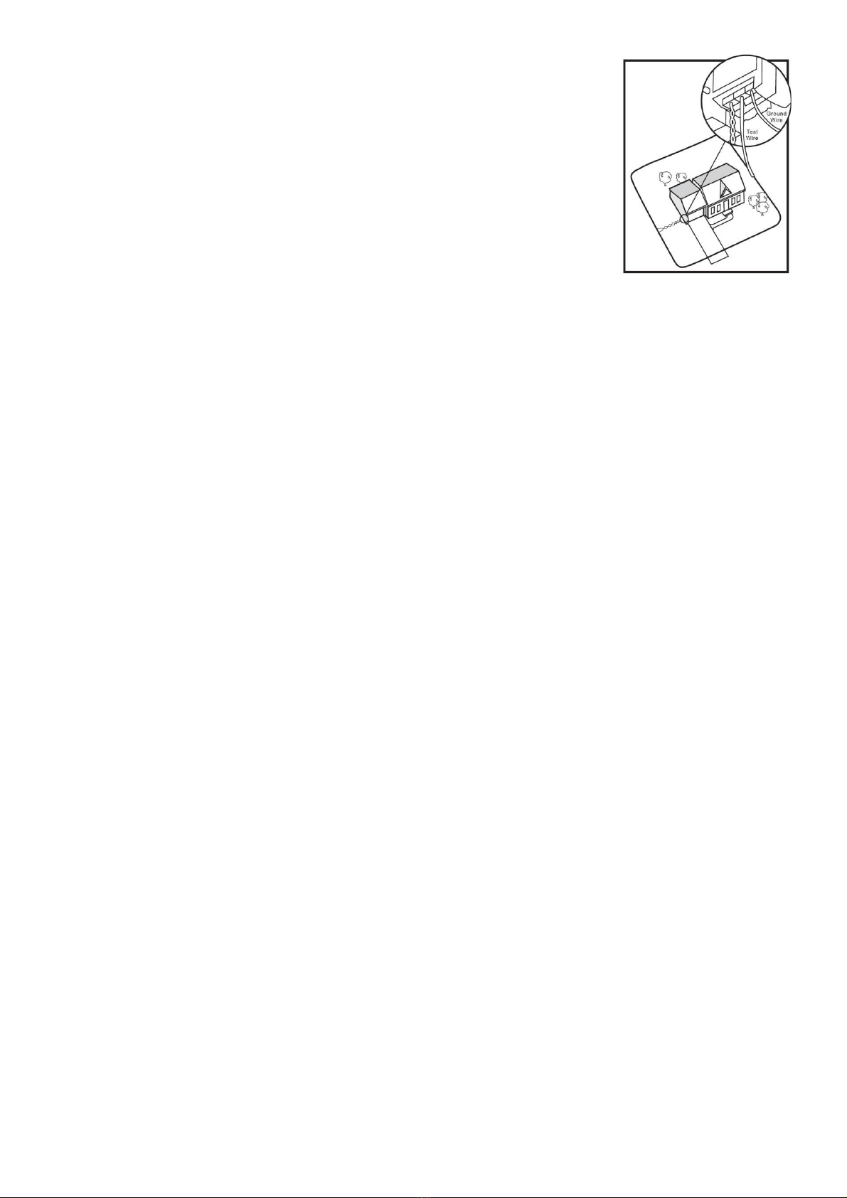
Ground wire (4B)
If you are not using an anti-surge device, effective grounding is
required to minimise the risk of electrical power surges which can
damage the transmitter and/or power adapter.
To ground the unit:
•Use a solid (not stranded) ground wire (1 to 1.5mm core
insulated copper wire) with a ground rod and clamp.
These can be obtained at most electrical supply stores
•Bury the ground rod at least 1-metre deep into the earth in a
location as close as possible to the transmitter
•Connect one end of the ground wire to the BLACK ground
terminal located on the transmitter and the other end of the
ground wire to the ground rod
Fuse Protection (4C)
The transmitter is also equipped with a 250 volt, ½ amp fuse to help protect the unit’s electronic
circuitry from power surges. To locate the fuse, slide off the lid on the back of the transmitter as
shown in 4C.

9
© MGG Products New Zealand 2021
STEP 5: Preparing the collar-receiver
The maxi collar-receiver supplied with this system is suitable for dogs over 7kgs in weight.
For smaller breeds of dog, please contact MGG Products to advise on a more appropriate size of
collar-receiver.
Preparing the collar-receiver
•Determine the size of prongs required for your dog.
Larger prong size is suited to longer-haired dog breeds; shorter prongs for short-haired breeds.
Choose one set and screw these onto the contact probes of the collar-receiver
•Attach the collar-strap as per the diagram below. The strap should sit snugly against the back of
the collar-receiver box i.e. the reverse side of the prongs
Note: Fitting of the collar-receiver is described in STEP 9. This is to ensure the system is set-up
safely and all the checks have been made before commencing training of your dog
Charging the collar-receiver
1. Connect the charging cable to the mains adaptor. Plug into the mains & switch on, then connect
to the collar-receiver. A RED light on the collar-receiver indicates it is charging
2. When fully charged, the red light changes to BLUE
3. Disconnect the collar-receiver from the adaptor, the blue light will turn off
4. Switch off the mains power to the adaptor
5. The collar-receiver is ready to use
Important:
The first time the unit is charged takes approximately 8-6 hours to fully charge the collar-receiver
battery. The battery will hold approximately 2-3 weeks of charge
*Thereafter re-charging of the collar-receiver battery only requires 2-3 hours recharge*
DO NOT exceed 2-3 hours of recharging
DO NOT recharge overnight or for longer than the stated times
Overcharging of the collar-receiver battery can lead to damage of the internal workings of the
system which is NOT COVERED under warranty.
MGG Maxi rechargeable collar-receiver
Suitable for dogs over 7kgs in weight
(Collar-strap colour & material can vary)
10
© MGG Products New Zealand 2021
Setting the warning level & intensity on the collar-receiver
There are 5-settings of warning intensity. Always start with the lowest setting first & monitor your
dog’s response.
•To turn ON the collar-receiver, PRESS & HOLD the ON/OFF button until the collar beeps
TWICE, then release
•To set the appropriate level of warning, SHORT-PRESS the button.
Each short-press of the button will gradually increase the warning intensity which is indicated by
the number of light flashes. For example:
1 short-press = light flashes ONCE for an audible BEEP to warn your dog
2 short-presses = light flashes TWICE for mild intensity static-correction
3 short presses = light flashes 3-TIMES for moderate intensity static-correction
4 short presses = light flashes 4-TIMES for strong intensity static-correction
•Once set, the warning level will remain the same unless you change it with the short-press of
the button
•To switch OFF the collar-receiver, PRESS & HOLD the ON/OFF button until the collar-receiver
beeps once
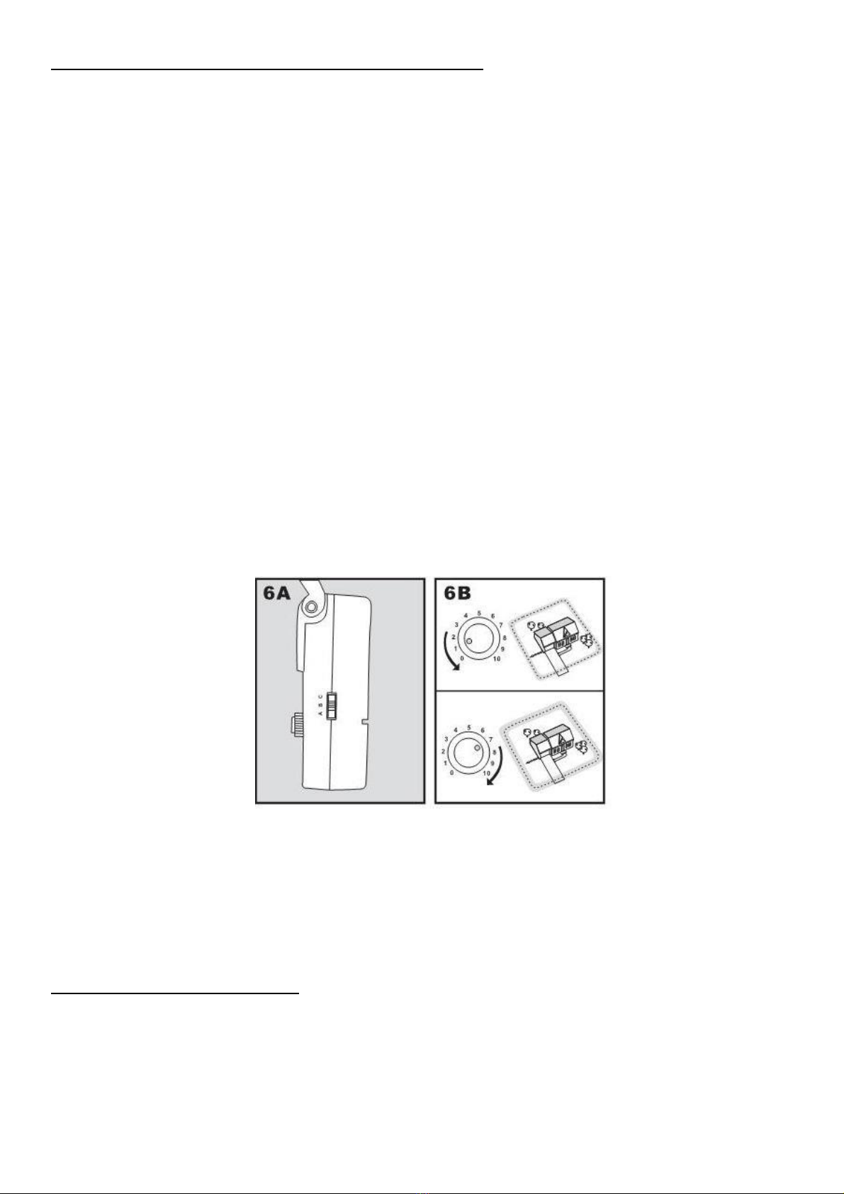
STEP 6: Setting the boundary-width & testing the collar-receiver
To set the width of boundary zone, determine the total amount of boundary-wire being used. Then
select the appropriate setting with the boundary control switch, located on the side of the
transmitter (6A). There are THREE settings:
A - use this setting for distances of over 750m of boundary-wire
B- use this setting for up to 400m of boundary-wire
C - use this setting for distances between 400m –750m boundary-wire
Once the boundary-control switch has been set to the correct length of wire used, then set the
width of the static-correction zone using the Boundary-width control knob located on the front of
the transmitter (6B).
Set the boundary-width as wide as possible (minimum 2m is recommended) to give your dog a
large enough static-correction zone without further reducing the overall dog containment area.
Note: The Boundary-width control knob does not alter the intensity of static-correction. This is
covered in STEP 5 –setting the warning level and intensity on the collar-receiver
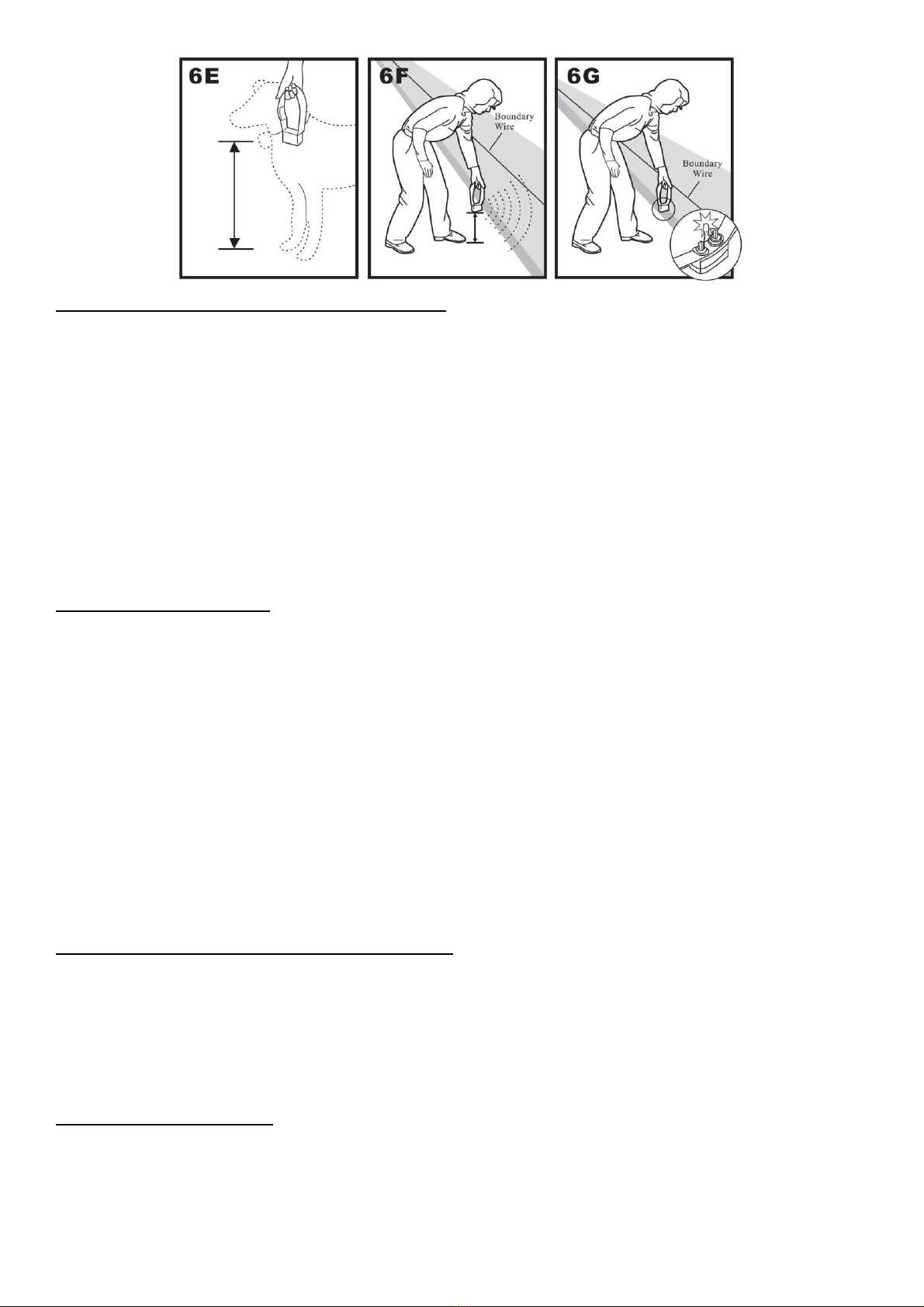
Setting the static-correction zone
•Ensure the collar-receiver is prepared and fully charged as per STEP 5
•Set the collar-receiver to setting 1 (beep only) as described above
•Attach the collar-receiver test light to the collar-receiver prongs (contact points)
•Holding the collar-strap at the level of your dog’s neck, with the prongs pointing upwards (6E),
walk towards the boundary-wire until the collar-receiver beeps and the test light flashes (6F &
6G)
11
© MGG Products New Zealand 2021
Adjusting the width of the static-correction zone
Turn the Boundary-width control knob CLOCKWISE to INCREASE the width of the static-
correction zone. Turn ANTI-CLOCKWISE to REDUCE it. Repeat this procedure as needed until
the collar-receiver beeps and the test light flashes at the desired distance from the boundary-wire
Note: The numbers on the Boundary-width control knob indicate signal strength i.e. the higher the
number the wider the boundary.
TIP: If adjustment of the Boundary--width control knob does not give the desired range, change
the setting (A, B or C) of the Boundary-control switch (located on the side of the transmitter).
TIP: If using a Double Loop, you may need to increase the distance of separation between the
boundary-wires to achieve the desired range (Sample 3, page 6)
Testing the collar-receiver
The collar-receiver beeps as a warning tone and ticks when delivering a static-correction. Walk
towards the boundary-wire, as previously instructed in diagrams 6E, 6F & 6G. On entering the
static-correction zone, the collar-receiver will beep, tick and the test-light should flash. This
indicates the static-correction has been delivered (6G).
It is recommended that you repeat this test in several areas of the dog containment area to ensure
the system is working where it is intended.
Once complete, remove the test-light from the collar-receiver prongs. You are now ready to
complete the installation of the boundary-wire. If the collar-receiver did not beep and the test light
did not flash, please refer to the ‘Troubleshooting’section (page 17).
STEP 7: Installing the boundary-wire
The following section covers various options to safely install the boundary-wire.
Attaching the boundary-wire to an existing fence
The boundary-wire of the MGG Maxi Dog Containment system can be attached using cable ties to
an existing fence. The boundary-wire can be attached as high as needed, although you will need
to ensure that the boundary-width is set to a sufficient range for the collar-receiver to receive the
signal.
Caution: Do not staple the boundary-wire to the fence as this may damage the insulation and the
function of the system
Burying the boundary-wire
In situations where the boundary-wire cannot be attached to an existing fence, it is recommended
to bury the wire as follows:
•Using the edge of a flat spade, cut a slit approximately 2 to 6cm deep along your planned
boundary

12
© MGG Products New Zealand 2021
•Place the boundary-wire carefully into the slit maintaining some slack to allow for expansion and
contraction with temperature variations
•Carefully secure the boundary-wire into the slit using a blunt tool such as a wooden spatula to
avoid damaging the wire
Crossing hard surfaces / driveways (7D)
•Place the boundary-wire in a convenient expansion
slot or create a groove using a circular saw and
masonry blade
•For best results, clean out with a brush any dust or
debris before inserting the wire
•Cover with an appropriate patching compound, such
as a bead of silicone
Crossing a gravel or dirt driveway (7E)
Place the boundary-wire in a PVC pipe or water hose to
protect the wire before burying.
STEP 8: Placing the boundary training flags
During the training period, the boundary training flags are useful visual reminders for your dog of
where the static-correction zone lies. Place the flags as follows:
•Hold the collar-receiver by the strap at the height
of your dog’s neck
•Walk towards the static-correction zone until the
collar-receiver beeps (8A).
•Place a boundary training flag in the ground (8B).
•Walk back into the dog containment area until the
beeping stops
•Repeat this process around the entire perimeter of
the dog containment area until it is marked with
boundary training flags approximately every 3
metres
With the boundary-wire fully installed, the collar-receiver tested and static-correction zone marked
with training flags, it is time to introduce your dog to the system.
STEP 9: Fitting the collar-receiver
Careful and correct placement of the collar-receiver is important for both training and effective use
of the dog containment system. The collar-receiver should be placed as follows:
1. Before starting, the transmitter must be turned OFF
2. Start with your dog standing comfortably (not sitting) (9A)
3. Centre the prongs on the underside of your dog’s neck. The prongs need to make direct
contact with the skin. Trimming of the fur will be required in longer-haired dog breeds, to
achieve this
4. Check the tightness of the collar-strap by
inserting one finger between the collar
and your dog’s neck. The fit should be
snug but not constricting (9B)
5. Allow your dog to wear the collar-
receiver for several minutes, then
recheck the fit. This should be repeated
as your dog becomes more comfortable
with the collar-receiver

13
© MGG Products New Zealand 2021
6. The collar-receiver strap is adjustable. You may need to
remove excess strap length as follows:
- mark the desired length of the collar-strap with a pen (9C)
allowing for growth if your dog is young, or grows a thicker
winter coat
- remove the collar-receiver from your dog. Cut the excess
strapping with scissors. If it is a fabric collar, heat seal the
cut end to avoid fabric fraying
IMPORTANT:
For comfort, safety and effectiveness of the system please ensure the following:
•Check the fit of the collar-receiver by being able to insert one finger between the collar and
your dog’s neck
•The dog should not wear the collar-receiver for more than 12-hours in any one day
•On a daily basis, examine the contact area of the prongs to the dog’s skin for any signs of skin
irritation, rash or skin sores. If this is observed, discontinue the use of the collar-receiver until
the skin is fully healed. If the condition persists beyond 48 hours, see your veterinarian
•On a weekly basis, wash the underside skin area of your dog’s neck together with the prongs
using a mild hand soap and water, rinse and dry thoroughly. Check the prongs for tightness
With the collar-receiver correctly fitted, you are ready to start training your dog with the system.
STEP 10: TRAINING GUIDE
Correct training of your dog is essential to the effectiveness of the Maxi Dog Containment System.
Read this section completely before embarking on training your dog. Remember that the MGG
Maxi Dog Containment System is not a solid barrier. Training is a process as follows:
•Be patient with your dog
•Training should be fun, fair, firm and consistent
•Make training sessions short. Train for a maximum 10 to 15 minutes at a time
•Do not try to do too much too quickly. Frequent, short sessions work best
•If your dog shows signs of stress, slow down the training schedule, add additional days of
training or increase the amount of play time with your dog in the dog containment area.
Common stress signals include:
❖Dog pulling on leash toward the house
❖Ears tucked
❖Tail down
❖Body lowered
❖Nervous/frantic movement or stiffening of dog’s body
•Your dog must be completely comfortable near the boundary training flags at the end of every
training session. Spend at least 5 minutes of “play time” at the completion of each session
within 3 metres of the boundary training flags
•Remove the collar-receiver after each training session
•Finish each training session on a positive note with lots of praise and play
•Be sure to contain your dog by another means during the training period (e.g. pen, tie-out,
leash, etc.)
Important
The aim of training is to teach your dog not to cross the boundary line and remain in the dog
containment area. However, there are times you will want the dog to cross the boundary and
leave the containment area with you. On these occasions, you need to demonstrate to the dog
that it is safe to do so. This is achieved by:
14
© MGG Products New Zealand 2021
1. Putting the dog on the leash
2. Remove the collar-receiver & turn it OFF
3. The dog can be now cross the boundary line safely WITH YOU LEADING the dog on the
leash; or carrying the dog over the boundary line or taking it in the car and driving over the
boundary line. This is imperative during the training process to reinforce a distinction
between when it is safe to cross the boundary and when it is not.
Day 1 –Boundary flag awareness phase
The aim of the first day’s training session is to introduce your dog to the boundaries of the dog
containment area using the combination of boundary training flags and warning beep from the
collar-receiver. Ideally, 3-short 10-15 minute sessions for day 1.
Setup
•Outside of the dog containment area, put a separate non-metallic collar on your dog’s neck and
attach a leash
•If your dog is food-responsive, it is ideal to have a bag of tiny pieces of edible treats as rewards
for correct behaviour. Alternatively, use your dog’s favourite toy as a reward
Steps
1. Walk your dog on a leash into the centre of the dog containment area. Calmly praise and talk
to your dog.
2. Prepare the collar-receiver by switching it ON and setting it to BEEP ONLY MODE as outlined
in “Setting the warning & intensity on the collar-receiver” on page 10.
3. Place the collar-receiver on your dog, positioning it BELOW the additional collar and leash.
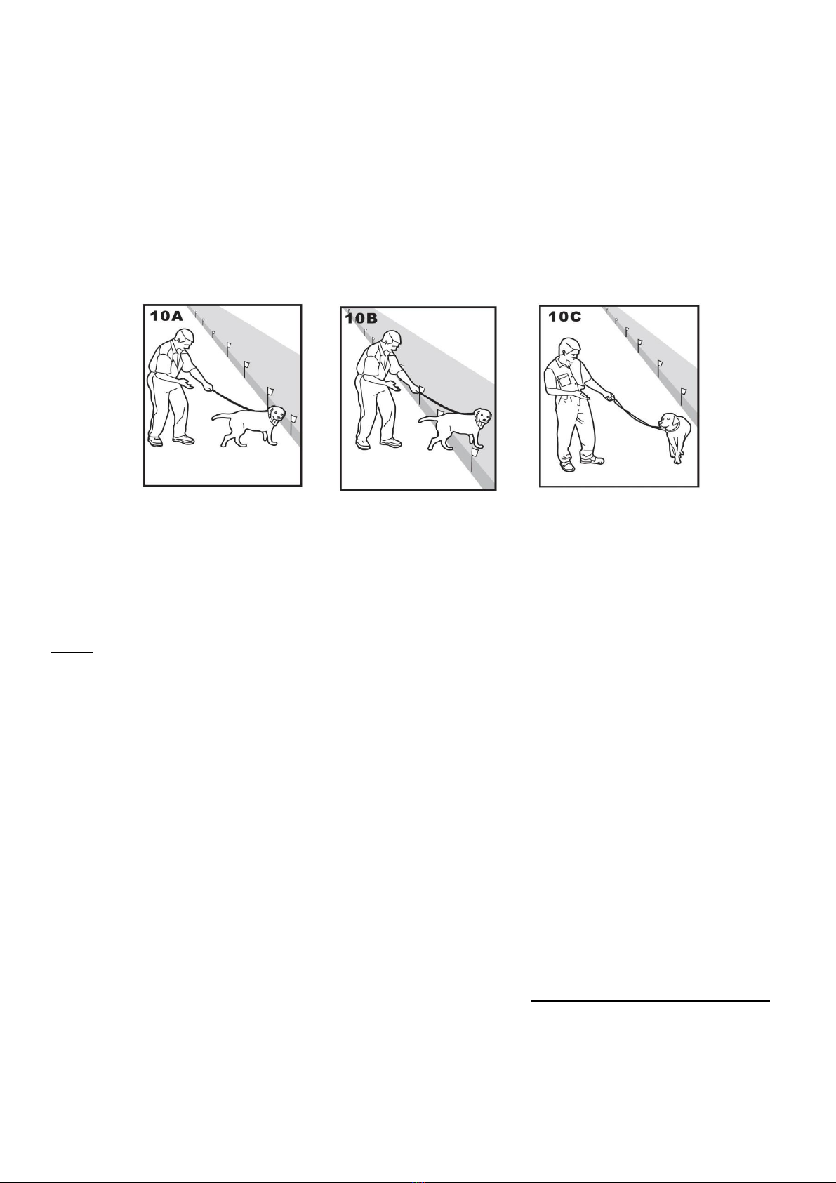
4. Begin by walking the dog towards the boundary training flags (10A). Keeping your mood
relaxed and with full control of your dog on the leash, toss a treat beyond the boundary flags
and within the static-correction zone. Allow your dog to enter the static-correction zone to
attempt to recover the treat (10B). As soon as the beep signal occurs, gently tug the leash and
guide your dog swiftly back into the dog containment area (10C).Immediately praise your dog
inside the dog containment area.
5. Repeat step 4 at the same point once or twice more. Do not allow your dog to retrieve or eat
the treat in the static-correction zone. Treats should only be eaten by the dog as a reward
within the dog containment area only.
6. Once your dog is familiar with the BEEP at the same boundary point, take the dog to several
different boundary flags. Your dog should start to resist attempting to retrieve the treat in the
static-correction zone.
7. End this first training session by removing the collar-receiver inside the dog containment area
and turn the collar-receiver OFF. Take a few minutes to praise and play with your dog. When
you are ready to leave the dog containment area, remove the collar-receiver, ensure your dog
is on the leash and you lead the dog across the boundary line. Your dog will learn this is a
safe way to get across the boundary with you.

15
© MGG Products New Zealand 2021
Days 2 onwards –Continue boundary flag awareness
Short training sessions which happen consistently (ideally 2–3 times per day) will encourage your
dog to quickly identify where the boundary zone lies. This is achieved by repeating steps 1-7 in
DAY 1. Once your dog is aware of the boundary line with the BEEP mode, it is time for your dog
to receive the static-correction. It is important you are there with your dog to ensure the dog’s
safety and give positive reassurance. Steps to train your dog with the static-correction are as
follows:
8. Following the steps of DAY 1 training, set the collar-receiver to MILD intensity static-correction
as outlined in “Setting the warning & intensity on the collar-receiver” on page 10.
Important
Always start the static-correction at the LOWEST intensity level
9. Continue to follow the steps 4 –7 of DAY 1 training, allowing your dog to attempt to retrieve
the treat from the static-correction zone. At the same time as the audible BEEP occurs, a
mild-intensity static-correction is delivered. Tug the leash to pull your dog away from the static-
correction zone back into the dog containment area.
10. Monitor your dog’s reaction to the change of correction for any of the reactions or behaviours
listed on page 13. Be reassuring with your dog within the dog containment area. This
reinforces the zone as a safe area.
11. Repeat steps 4-7 using the mild-static-correction plus beep in several other areas. Be vigilant
to your dog’s reaction. Discontinue training if your dog is showing any indicators of stress as
listed on page 13.
Important
For some dogs, the BEEP is a sufficient warning signal as to the boundary line whilst others
will require the combination with the static-correction. Always start at the lowest level of
intensity of static-correction and increase in gradual increments of intensity as outlined in
“Setting the warning & intensity on the collar-receiver” on page 10.
Distraction training
Once you feel your dog is aware of the boundary-line whilst on the leash during training session, it
is time to train your dog within the dog containment area with distractions outside of the boundary
line. This is achieved as follows:
12. With full control of your dog on the leash, continue following steps 4-11.
13. Create distractions which tempt your dog into the static-correction zone, such as:
- A second person standing on the other side of the static-correction zone
- Throw a ball outside of the dog containment area
- Have a neighbour walk their dog outside of the dog containment area
14. If your dog does not move toward the distraction, praise and offer a treat.
15. If your dog does react to the distraction, allow your dog to go into the static-correction zone. If
they do not return after 3-seconds, tug gently on the leash and assist your dog back into the
dog containment area.
16. Treat and praise your dog each time your dog returns to the dog containment area with or
without help.
17. Repeat steps 12-16 with other distractions.
Gradually increase training session times to one hour. Once your dog demonstrates consistent
avoidance of the entire boundary line and remains within the dog containment area regardless of
distractions (whilst leashed), it is time to start unleashed supervised training.

16
© MGG Products New Zealand 2021
Unleashed supervised training
The aim of these training sessions is to ensure your dog has free-
run of the dog containment area, off-leash but supervised. DO
NOT leave the dog unattended until you have completed this
section.
18. Starting with your dog in the dog containment area, set the
mode on the collar-receiver to the level of correction you have
been using in distraction training; turn it ON. Place the collar-
receiver on the dog and remove the leash (leaving the second
collar strap in place.
19. Walk around the dog containment area and play with your dog, staying within the boundary
zone at all times.
20. Pre-occupy yourself with another task in the dog containment zone whilst observing your dog.
21. Should your dog escape, retrieve your dog. Switch OFF the collar-receiver and remove it.
Attach the leash and lead your dog back into the dog containment area.
22. Repeat steps 18-21 until your dog remains within the dog containment area. This may take
several sessions.
Only when your dog is familiar with the dog containment area and consistently demonstrates
awareness of its boundary regardless of distractions on the other side, can you move to
unsupervised freedom within the dog containment area.
When you are satisfied that your dog’s training is complete, remove every other boundary flag
once a week, until all the flags are removed. Save boundary flags for future use.
Taking your dog outside of the dog containment area
Once training is completed, your dog will be familiar with the boundary of the dog containment
area and will be reluctant to cross the boundary. If you have followed the training programme,
your dog will know it is safe to cross the boundary line when you have:
- Removed the collar-receiver and turned it OFF
- Leashed the dog and lead it across the boundary line, ideally at the same point
- Carry it across the boundary line
- Placed it in a car to cross the boundary line
Important
The entire family need to be taught the training and “rules” your dog understands with the MGG
Maxi Dog Containment System. Consistency is key here to ensuring your dog does not get mixed
messages and become confused. As such, it is important to establish a routine with your dog in
terms of entering and leaving the dog containment area. All family members/house or dog-sitters
need to be familiar with this routine. Your dog needs to know that the only way to safely leave the
dog containment area is leashed, with the collar-receiver removed and with a person.
Congratulations! You have now successfully completed the training programme

17
© MGG Products New Zealand 2021
Trouble-shooting
The following are suggestion to resolve some of the common issues which may arise with the dog
containment system. Please follow these. If unresolved, call MGG Product Services to speak with
a staff member for advice: Freephone 0800 449 669 (Mon-Fri 9.15am to 4pm)
Problem
Suggestions to resolve the issue
Collar-receiver is not
beeping or delivering a
static-correction
•Ensure the collar-receiver is fully charged as per STEP 5 ‘Charging the collar-
receiver’on page 9
•Check both power and loop indicator lights are illuminated on the transmitter. If not,
perform the short-loop test as outlined on page 18
The collar-receiver is
beeping but the dog is
not responding to the
static-correction
•Re-test the collar-receiver with the test-light as outlined on page 11
•If the test-light flashes, check the fit of the collar-receiver on your dog as outlined in
STEP 9 ‘Fitting the collar-receiver’ on page 12
•It may be necessary to trim the fur where the prongs make contact with the skin of
the underside of your dog’s neck. Alternatively you may need to change to the
longer length prongs to ensure good skin contact is achieved
•Repeat training steps to reinforce boundary lines
•Increase the intensity of the static-correction level as per page 10
The collar-receiver does
not activate until the dog
is on or across the
boundary-wire
•Ensure the collar-receiver is fully charged as per STEP 5 on page 9
•On the transmitter, adjust the boundary-width by turning the Boundary-width control
knob CLOCKWISE to increase the distance of the static-correction zone i.e. from the
boundary-wire to the dog containment area where the collar-receiver is activated
•On the side of the transmitter change the setting using the boundary control switch
as outlined in STEP 6 on page 10
•If using a double loop, ensure there is a minimum separation between the boundary-
wires of 1 to 1.5 metres as outlined on page 6
•If the collar-receiver continues to activate only at the boundary wire, perform a short-
loop test as outlined on page 18
The collar-receiver
activates inside the
house
There are too many electrical appliances which have the potential to activate the collar-
receiver inside the house. We strongly recommend that collar-receivers are completely
removed from the dog in the dog containment area BEFORE the dog enters the house.
And dogs DO NOT wear collar-receivers inside the house.
However, there may be instances where the signal from the house can interfere with
the collar-receiver:
•If the boundary-wire is positioned too close to the house, the signal can transmit
through the walls of your house. Ensure the boundary-wires are twisted from the
transmitter to the boundary as outlined in STEP 3 on page 7
There is an inconsistent
signal
•Ensure the transmitter is at least 1-metre from any large metal objects or appliances
•Check that ALL corners of the boundary-wire are gradual, as outlined in STEP 2 on
page 5
•Make sure the boundary-wire is not running parallel to, or within 1.5 metres of
electrical wires, neighbouring containment systems, telephone wires, television or
antenna cables, or satellite dishes
The power & loop
indicator lights are off
•Check that the power adapter is plugged into the transmitter
•Try plugging the transmitter into another 240 volt outlet
•Remove the fuse door on the back of the transmitter and change the fuse
•If the lights still do not come on, the transmitter and/or power adapter may need to be
replaced
The power light is on,
the loop indicator light is
off & the transmitter loop
alarm is sounding
•Ensure both ends of the boundary-wire are plugged into Boundary-wire terminals of
the transmitter. Check that 1cm of the insulation is stripped so that the copper wire is
exposed and making a direct connection to the terminals
•Perform the short-loop test as outlined on page 18 to determine if the fault lies with
the transmitter or if there is a break in the boundary-wire
•If a break in the boundary-wire is identified, refer to ‘Locating a break in the
boundary-wire’ system on page 18
The fuse on the
transmitter blows when
it is replaced
•Ensure a surge protector is in place. If the fuse continues to blow, the transmitter
and/or power adaptor need to be replaced
18
© MGG Products New Zealand 2021
Short-loop test
The short-loop test is a simple test to determine if individual components
of the containment system (transmitter, collar-receiver and boundary-
wire) are functioning properly. This is achieved as follows:
1. Disconnect the boundary-wire and grounding wire (if used).
2. Cut approximately 4 metres of unused boundary-wire and connect it
to the Boundary-wire terminals of the transmitter in a short-loop.
3. Spread the boundary-wire out into a circle. Set the Boundary-control
switch on the side of the transmitter to position B.
4. Set the Boundary-width control knob on the front of the transmitter to
level 10.
5. When the loop-indicator light is NOT LIT, the transmitter may not be functioning correctly.
6. If the loop-indicator light DOES light up, disconnect one end of the test-loop from the
Boundary-wire terminal. The loop-alarm should sound. If this does not happen, the transmitter
needs to be replaced.
7. When the loop-alarm sounds, plug the test-loop wire back into the Boundary-wire terminal of
the transmitter.
8. Turn the collar-receiver ON and set it to the beep and static-correction mode (as per page 10).
Attach the test-light bulb to the collar-receiver. Hold the collar-receiver next to the test-loop
wire. The collar-receiver should beep up to 30cm away from the test-loop wire. The test-light
should flash as you hold the collar-receiver closer to the test-loop wire.
9. If the collar-receiver does not beep and/or the test-light does not flash, try re-charging the
collar-receiver and repeat the test again.
10. When the collar-receiver beeps and the test-light flashes, this shows that both the transmitter
and collar-receiver are functioning correctly. Therefore the issue lies with the boundary-wire.
To locate a break in the boundary-wire
1. Remove the short-test loop and reconnect the boundary-wire to the terminals on the
transmitter.
2. Using the plan of your boundary-wire layout, locate the original wire splicing. Ensure they are
in a good, solid and waterproof condition. If not, re-join the boundary-wire with the supplied
heatshrink water-proof joiners (page 7)
3. Check your yard to determine any other possible damage to the boundary-wire. For example,
recent digging, rodent burrowing or any other noticeable disturbance which could be the cause
of a possible break. If you cannot find an obvious break in the boundary-wire the simplest
solution is to replace the wire.
MGG Products helpline
MGG Products offer a trouble-shooting telephone service. It is advised that you have this manual
with you when you speak to one of our team.
Call Freephone 0800 449 669 weekdays 9.15am to 4pm

19
© MGG Products New Zealand 2021
Terms of use and limitation of liability
1. Terms of Use
This product is offered to you conditional upon your acceptance without modification of the
terms, conditions and notices contained herein. Usage of this product implies acceptance of
all such terms, conditions and notices as outlined on our website mggproducts.co.nz
2. Proper Use
This product is designed for use with dogs where training is desired. The specific
temperament of your dog may not work with this product. We DO NOT recommend this
product in dogs with aggressive behaviours. If you are unsure whether this is appropriate for
your dog, please consult your veterinarian or certified trainer.
Proper use includes reading this entire instruction manual BEFORE set-up and includes any
specific caution or important statements.
3. No unlawful or prohibited use
This product is designed for use with dogs only. This dog training device is not intended to
harm, injure or provoke.
4. Limitation of liability
In no event shall MGG Products be liable for any direct, indirect, punitive, incidental, special or
consequential damages, or any damages whatsoever arising out of or connected with the use
or misuse of this product. Buyer assumes all risks and liability from the use of this product.
5. Modification of terms and conditions
MGG Products reserves the right to change the terms, conditions and notices under which this
product is offered.
CAUTION
The MGG Maxi Dog Containment System is NOT a solid barrier. The system is designed to act as
a deterrent to remind dogs (via static-correction) to remain within the boundary established. It is
important that you reinforce training with your dog on a regular basis.
Since the tolerance level to static-correction varies from dog to dog, MGG Products CANNOT
guarantee that the system will, in all cases, keep a dog within the established boundary.
Furthermore, not all dogs can be trained to avoid crossing the boundary! Therefore, if you have
reason to believe that your dog may pose a danger to others, or harm itself if it is not kept from
crossing the boundaries, you should NOT rely solely upon the MGG Maxi Dog Containment
System to confine your dog.
MGG Products shall NOT BE LIABLE for any property damage, economic loss or any
consequential damages, sustained as a result of any animal crossing the boundary.

Other manuals for Maxi
1
Table of contents
Other MGG Pet Care Product manuals


