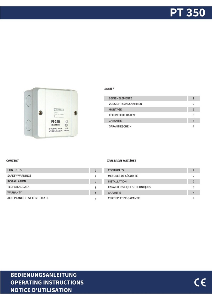
Mi-Heat E91 User manual

Einsatzbereich
Der E91 Thermostat kann zur Regelung von Fußbodenheizsystemen wie z.B. elektrischen Heizmatten oder Heizfolien, sowie für NC-Stellventile (normally closed /
stromlos geschlossen) für wassergeführte Bodenheizungen eingesetzt werden. Über das Wochenprogram sorgt das Thermostat dafür, dass die gewünschte
Temperatur zur gewünschten Zeit zur Verfügung steht.
Wichtige Hinweise
•Wir empfehlen, die Montage des Temperaturreglers und der Heizanlage Fachkräften zu überlassen.
•Die elektrischen Verbindungen und den Netzanschluss des Gerätes sollten nur qualifizierte Elektrofachkräfte ausführen.
•Trennen Sie die Leitungen vom Strom bevor Sie ein Thermostat installieren, überprüfen oder austauschen.
•Den Schaltplan und die Montagehinweise zum Gerät finden Sie in dieser Anleitung.
•Die Herstellergarantie erstreckt sich nicht auf Fehlfunktionen des Gerätes, die infolge mechanischer Beschädigung, fehlerhafter Montage, unsachgemäßer
Handhabung und bei der Nutzung für Zwecke oder Bedingungen die nicht in der vorliegenden Montage- und Gebrauchsanweisung aufgeführt sind,
entstehen.
Sicherheitshinweise
Trennen Sie die Leitungen von der Spannung bevor Sie ein Thermostat installieren, überprüfen oder austauschen. Die Arbeiten an elektrischen Verbindungen
und dem Netzanschluss des Gerätes dürfen nur von qualifizierten Elektrofachkräften durchgeführt werden. Andernfalls erlischt die Garantie. Es dürfen nur
Kunststoffunterputzdosen für die Thermostatinstallation eingesetzt werden. Stellen Sie während der Installation des Wellrohrs und nochmals vor der
Verlegung des Estrichs sicher, dass der Sensor im Wellrohr verlegt und wieder herausgenommen werden kann.
Achtung!
Der Bodensensor fungiert als Temperaturbegrenzer. Die Bodenbegrenzungs-Temperatur muss in den Einstellungen „3LIT“ festgelegt werden.
Empfohlene Einstellungen:
•Max. Temperatur Fliesenboden: + 45 ° C
•Max. Temperatur Holz-, Laminatboden: + 27 ° C
•Max. Temperatur Vinyl-, PVC-Boden: es ist die vom Bodenbelagshersteller angegebene maximal Temperatur einzustellen
Display-Symbole:
Funktionen:
Seite 1-4
Page 5-8
Mi-Heat Heizsysteme GmbH
Ol Streek 39a | 26607 Aurich | Deutschland
Tel.: +49 (0)4941-6971930 | Web: mi-heat.com | Mail: info@infrarot-fussboden.de

2
Technische Daten: Schaltplan:
Spannung
230 VAC, 50-60 Hz
Max. Schaltleistung
16A
Stromverbrauch
2 W
Temperatureinstellbereich
+5 bis +90°C
IP-Schutz
IP20
Temperatur-Begrenzung
+5 bis +60°C (Standard: 35°C)
Hysterese
0.5-10°C (Standard 1.0°C)
Umgebungstemperaturbereich
-5 ~ 50°C
Bodensensor R25°C
10kOhm
Programmierung:
Drücken Sie die Menu Taste für 5 Sekunden um mit der Programmierung zu
beginnen.
Anmerkung:
1) Der vorprogrammierte Sollwert (15°C) für Ereignis 3&4 ist
derselbe wie bei Ereignis 2, bitte stellen Sie diesen Ihren
individuellen Anforderungen entsprechend ein.
2) Das Symbol "OFF" wird angezeigt, wenn der Sollwert den
minimalen Einstellwert erreicht und der Thermostat in diesem
Ereignis ausgeschaltet wird.
Abmessungen (mm):
Montageschritte:
1. Lösen Sie die Frontabdeckung, indem Sie einen Schraubendreher in den
unteren Schlitz stecken.
2. Demontieren Sie die Montageplatte nach folgendem Schema.
3. Befestigen Sie die Montageplatte mit einem Schraubendreher in der
Wand-Montagedose/Hohlwanddose.
4. Nach dem Anschluss der Drähte (siehe Schaltplan) wird der Thermostat auf
die Montageplatte montiert und der Rahmen wieder aufgesetzt.

3
Bedienung:
1. Thermostat Ein- bzw. Ausschalten
2. Drücken Sie im Modus Wochenprogramm die Taste ▲oder ▼um die temporäre Steuerung zu aktivieren.
3. Verwenden Sie die Tasten HOCH ▲oder RUNTER ▼zur Einstellung des Temperaturwertes.
4. Drücken Sie die Taste für 5 Sekunden, um die Einstellung für den Tag und die Uhrzeit vorzunehmen. Stellen Sie mit den Tasten ▲/ ▼die
Minuten ein, durch drücken der gelangen Sie zur Einstellung der Stunde, stellen Sie diese mit den Tasten ▲/ ▼ein. Durch erneutes drücken der
gelangen Sie zur Tag-Einstellung (1-7 / Mo.-So.) stellen Sie den aktuellen Tag mit den Tasten ▲/ ▼ein und drücken Sie erneute um die
Einstellung zu speichern.
5. Drücken Sie die Taste , um den Modus (manuell / Wochenprogramm) zu wählen.
6. Im Modus Wochenprogramm wird abwechselnd die SOLL-Temperatur und Uhrzeit unten im Display angezeigt. Die IST-Raumtemperatur kann mittig
im Display direkt abgelesen werden.
7. Um die Tastensperre zu aktivieren bzw. deaktivieren, drücken Sie die Taste ▲und ▼gleichzeitig für 5 Sekunden. Bei aktiver Tastensperre erscheint
das -Symbol im Display.
Erweiterte Einstellungen:
Um die erweiterten Einstellungen aufzurufen, ist das Gerät zunächst auszuschalten (OFF steht im Display).
Drücken Sie anschließend die Taste und gleichzeitig die Taste.
1ADJ: Kalibrierung Temperatur-Sensor.
Taste ▲oder ▼drücken um Wert einzustellen.
Einstellbar zwischen -9,9 und +9,9°C. Standard 0,0°C.
Menu Taste drücken, für nächsten Schritt.
6PRG: Tag/Gruppierung für die
Wochenprogrammierung einstellen.
Taste ▲oder ▼drücken um Wert einzustellen.
Modus 5/2-Tage (Mo.-Fr. + Sa.-So.)
Modus 6/1-Tage (Mo.-Sa. + So.)
Modus 7 Tage (Mo-So.)
Modus OFF (kein Wochenprogramm)
Menu Taste drücken, für nächsten Schritt.
2SEN: Auswahl des Sensormodus.
Taste ▲oder ▼drücken um Wert einzustellen.
IN: interner Sensor
OUT: Bodensensor
ALL: Beide Sensoren, Bodensensor ist der
Grenzwertgeber
Menu Taste drücken, für nächsten Schritt.
7RLE: Funktion bei diesem Model nicht verfügbar.
Menu Taste drücken, für nächsten Schritt.
3LIT: Einstellung der Temperaturbegrenzung
Taste ▲oder ▼drücken um Wert einzustellen.
Einstellbar zwischen +5 und +60°C. Standard 0,0°C.
Menu Taste drücken, für nächsten Schritt.
8DLY: Funktion bei diesem Model nicht verfügbar.
Menu Taste drücken, für nächsten Schritt.
4DIF: Einstellung der Hysterese
Taste ▲oder ▼drücken um Wert einzustellen.
Einstellbar zwischen +0,5 und +10°C. Standard 1,0°C.
Menu Taste drücken, für nächsten Schritt.
9HIT: Einstellung der Max. Temperatur
Taste ▲oder ▼drücken um Wert einzustellen.
Einstellbar zwischen +35 und +90°C. Standard 50°C.
Menu Taste drücken, für nächsten Schritt.
5LTP: Frostschutzfunktion
Taste ▲oder ▼drücken um Wert (OFF/ON)
einzustellen.
Menu Taste drücken, für nächsten Schritt.
AFAC: Zurücksetzen auf Werkseinstellung
Taste ▲solange drücken, bis --- im Display erscheint
Anschließend die Taste drücken.

4
Sensor Installation:
Wir empfehlen, den Bodensensor in einem Wellrohr (Ø 16mm –s. Bild)
zu verlegen, um diesen im Fall eines Fehlers problemlos austauschen zu können.
Für Informationen, wie Sie den Bodensensor auf Ihrer Heizung anbringen müssen,
lesen Sie bitte die Installations- und Betriebsanleitung Ihrer Heizmatte.
Sensor Fehler:
E0: interner Sensor kurzgeschlossen oder getrennt.
E1: externer Sensor kurzgeschlossen oder getrennt.
Wenn Fehler E0/E1 angezeigt wird, sollten Sie das Thermostat überprüfen und der
Fehler zu beseitigen.
Entsorgungshinweis
Dieses Gerät nicht im Hausmüll entsorgen! Elektronische Geräte sind
entsprechend der Elektro- und Elektronik-Altgeräte Richtlinie über die örtlichen
Sammelstellen für Elektronik-Altgeräte zu entsorgen.
Hinweis zur Konformität
Das CE-Zeichen ist ein Freiverkehrszeichen, dass sich ausschließlich an die
Behörden wendet und keine Zusicherung von Eigenschaften beinhaltet
Dokumentation © 2022 Mi-Heat Heizsysteme GmbH
Alle Rechte vorbehalten. Ohne schriftliche Zustimmung des Herausgebers darf diese Anleitung auch nicht auszugsweise in irgendeiner Form reproduziert oder
vervielfältigt werden. Es ist möglich, dass das vorliegende Handbuch drucktechnische Mängel oder Druckfehler aufweist. Für Fehler technischer oder
drucktechnischer Art und ihre Folgen übernehmen wir keinerlei Haftung.
Mi-Heat Heizsysteme GmbH
Ol Streek 39a
26607 Aurich
Deutschland
Internet: mi-heat.de
E-Mail: info@infrarot-fussboden.de

5
Range of application
The E91 thermostat can be used to control floor heating systems such as electric heating mats or heating foils, as well as for NC control valves (normally closed)
for water-guided floor heating systems. Via the weekly programme, the thermostat ensures that the desired temperature is available at the desired time.
Important Notes
•We recommend leaving the installation of the temperature controller and the heating system to specialists.
•Only qualified electricians should carry out the electrical connections and the mains connection of the appliance.
•Disconnect the cables from the power supply before installing, checking or replacing a thermostat.
•The wiring diagram and installation instructions for the unit can be found in this manual.
The manufacturer's warranty does not cover malfunctions of the appliance that occur as a result of mechanical damage, faulty installation, improper handling and
use for purposes or under conditions not specified in these instructions for installation and use.
Safety instructions
Disconnect the cables from the power supply before installing, checking or replacing a thermostat. Work on electrical connections and the mains connection of
the appliance may only be carried out by qualified electricians. Failure to do so will invalidate the warranty. Only plastic flush-mounted boxes may be used for
thermostat installation. During installation of the corrugated pipe and again before laying the screed, make sure that the sensor can be placed in the
corrugated pipe and removed again.
Attention!
The floor sensor functions as a temperature limiter. The soil limiter temperature must be set in the "3LIT" settings.
Recommended settings:
•Max. Temperature tile floor: + 45 ° C
•Max. Temperature wood, laminate floor: + 27 ° C
•Max. Temperature vinyl, PVC flooring: the maximum temperature specified by the flooring manufacturer must be set.
Display symbols:
Functions:
Page 5-8
Mi-Heat Heizsysteme GmbH
Ol Streek 39a | 26607 Aurich | Germany
Tel.: +49 (0)4941-6971930 | Web: mi-heat.com | Mail: info@infrarot-fussboden.de
USER MANUAL

6
Technical data: Circuit diagram:
Voltage
230 VAC, 50-60 Hz
Max. Switching capacity
16A
Power consumption
2 W
Temperature setting range
+5 to +90°C
IP protection
IP20
Temperature limit
+5 to +60°C (Standard: 35°C)
Hysteresis
0.5-10°C (Standard 1.0°C)
Ambient temperature range
-5 ~ 50°C
Bodensensor R25°C
10kOhm
Programming:
Press the Menu button for 5 seconds to start programming.
Note:
1) The pre-programmed setpoint (15°C) for event 3&4 is the same
as for event 2, please adjust it according to your individual
requirements.
2) The "OFF" symbol is displayed when the setpoint reaches the
minimum setting value and the thermostat is switched off in this
event.
Dimensions (mm):
Assembly steps:
1. Loosen the front cover by inserting a screwdriver into the lower slot.
2. Dismantle the mounting plate according to the following diagram.
3. Secure the mounting plate in the wall mounting box/cavity wall box using
a screwdriver.
4. After connecting the wires (see circuit diagram), the thermostat is mounted
on the mounting plate and the frame is put back on.

7
Operation:
1. Switch the thermostat on or off
2. Press the ▲or ▼button in the weekly programme mode to activate the temporary control.
3. Use the UP ▲or DOWN ▼buttons to set the temperature value.
4. Press the button for 5 seconds to set the day and time. Set the minutes with the ▲/ ▼keys, pressing the to reach the hour setting, set it
with the ▲/ ▼keys. Press to set the current day (1-7 / Mon.-Sun.) with the ▲/ ▼keys and press again to save the setting.
5. Press the button , to select the mode (manual / weekly programme).
6. In the weekly programme mode, the SET temperature and time are shown alternately at the bottom of the display. The ACTUAL room temperature
can be read directly from the centre of the display.
7. To activate or deactivate the key lock, press the ▲and ▼key simultaneously for 5 seconds. When the key lock is active, the -symbol appears in
the display.
Advanced settings:
To access the advanced settings, first switch off the unit (OFF appears in the display).
Then press the and key at the same time.
1ADJ: Calibration temperature sensor.
Press the ▲or ▼key to set the value.
Adjustable between -9.9 and +9.9°C. Standard 0.0°C.
Press the Menu key for the next step.
6PRG: Set day/grouping for weekly programming.
Press the ▲or ▼key to set the value.
Mode 5/2-days (Mon.-Fri. + Sa.-Sun.)
Mode 6/1 days (Mon.-Sun. + Sun.)
Mode 7 days (Mon.-Sun.)
Mode OFF (no weekly programme)
Press the Menu key for the next step.
2SEN: Selection of the sensor mode.
Press the ▲or ▼key to set the value.
IN: internal sensor
OUT: floor sensor
ALL: both sensors, floor sensor is the limit sensor
Press the Menu key for the next step.
7RLE: Function not available on this model.
Press the Menu button for the next step.
3LIT: Setting the temperature limit
Press the ▲or ▼key to set the value.
Adjustable between +5 and +60°C. Standard 0.0°C.
Press the Menu key for the next step.
8DLY: Function not available on this model.
Press the Menu button for the next step.
4DIF: Setting the hysteresis
Press the ▲or ▼key to set the value.
Adjustable between +0.5 and +10°C. Standard 1.0°C.
Press the Menu key for the next step.
9HIT: Setting the max. Temperature
Press the ▲or ▼key to set the value.
Adjustable between +35 and +90°C. Standard 50°C.
Press the Menu button for the next step.
5LTP: Frost protection
Press the ▲or ▼key to set the value (OFF/ON).
Press the Menu button for the next step.
AFAC: Reset to factory setting
Press the ▲key until --- appears in the display.
Then press the button.

8
Sensor installation:
We recommend installing the floor sensor in a corrugated tube (Ø 16mm - see
picture).
in order to be able to replace it easily in the event of a fault.
For information on how to install the floor sensor on your heater, please read the
installation and operating instructions for your heating mat.
Sensor error:
E0: internal sensor short-circuited or disconnected.
E1: external sensor short-circuited or disconnected.
If error E0/E1 is displayed, you should check the thermostat and eliminate the error.
Disposal note
Do not dispose of this appliance in household waste! Electronic devices must be
disposed of in accordance with the Waste Electrical and Electronic Equipment
Directive via the local collection points for waste electronic equipment.
Note on conformity
The CE mark is an over-the-counter mark that is addressed exclusively to the
authorities and does not imply any assurance of properties.
Documentation © 2022 Mi-Heat Heizsysteme GmbH
All rights reserved. No part of this manual may be reproduced or duplicated in any form without the written consent of the publisher. It is possible that this
manual contains typographical defects or printing errors. We accept no liability for errors of a technical or printing nature and their consequences.
Mi-Heat Heizsysteme GmbH
Ol Streek 39a
26607 Aurich
Germany
Internet: mi-heat.com
E-Mail: info@infrarot-fussboden.de
This manual suits for next models
1
Table of contents
Languages:
Other Mi-Heat Thermostat manuals
Mi-Heat
Mi-Heat MST1 User manual

Mi-Heat
Mi-Heat TH213 User manual

Mi-Heat
Mi-Heat MH7H-EH User manual
Mi-Heat
Mi-Heat TH213 User manual
Mi-Heat
Mi-Heat SAS816RF User manual
Mi-Heat
Mi-Heat SAS918RF User manual
Mi-Heat
Mi-Heat MTS200 User manual

Mi-Heat
Mi-Heat Optima Wlan Classic User manual

Mi-Heat
Mi-Heat TC-500 Wifi User manual
Mi-Heat
Mi-Heat C16 User manual

