Microtest 7630 User manual

HI-POT TESTER
7630 7605
1.3
User Manual
02st Apr 2019

2
Table of Contents
1. Precautions before use .................................................................................................................4
1.1 Electrification and Electric Shock....................................................................................4
1.2 Ground .............................................................................................................................4
1.3 Power ...............................................................................................................................4
1.4 Connect the testing cable to the high voltage output terminal.........................................4
1.5 Warm up ...........................................................................................................................4
1.6 External control host ........................................................................................................4
1.7 Machine malfunction .......................................................................................................4
1.8 Test End............................................................................................................................4
1.9 Placement and Storage .....................................................................................................4
1.10 Emergency Measures .......................................................................................................4
2. General description ......................................................................................................................5
2.1 Package and Accessories..................................................................................................5
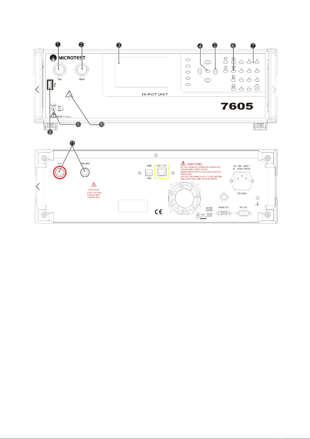
2.2 Front Panel .......................................................................................................................6
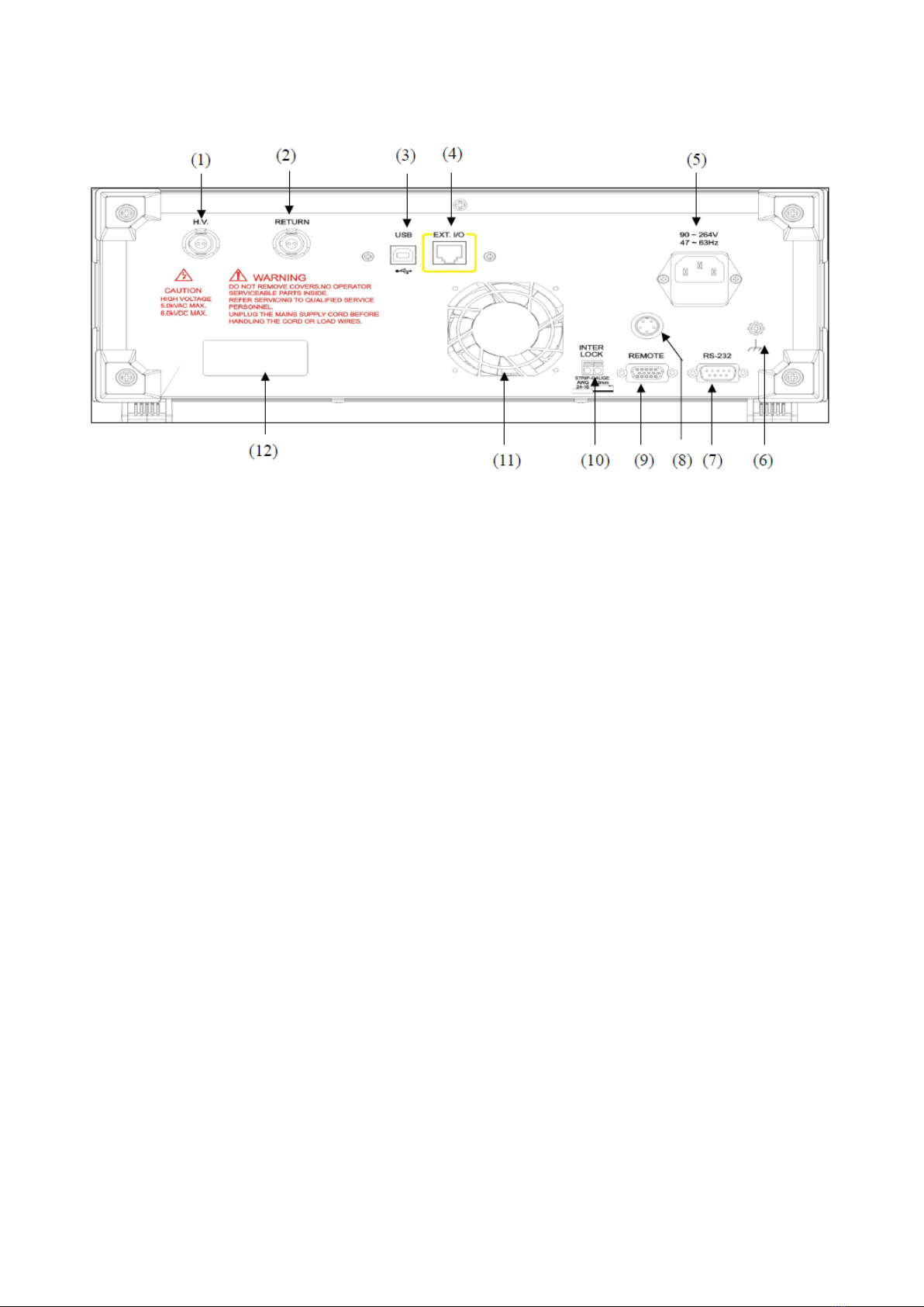
2.3 Rear Panel ........................................................................................................................8
3. Basic Operations ........................................................................................................................10
3.1 Function Block Diagram................................................................................................10
3.2 Standby Screen............................................................................................................... 11
3.3 System Settings (SYSTEM)...........................................................................................12
3.4 Function Setting (FUNC)...............................................................................................13
3.5 Specification Settings Description 1 (SETUP) ..............................................................14
3.6 Specific Setting Description 2 (SETUP)........................................................................15
3.7 File Management (FILE) ...............................................................................................17
4. Start test......................................................................................................................................20
4.1 Before testing .................................................................................................................20
4.2 Testing............................................................................................................................21
4.3 End Test..........................................................................................................................22
4.4 Releasing Determined Result.........................................................................................23
5. Remote Control I/O Description (REMOTE)............................................................................24
6. RS-232/USB DEVICE Instructions ...........................................................................................26
6.1 RS-232 interface specifications .....................................................................................26
6.2 Command Format ..........................................................................................................26
6.3 Connectors .....................................................................................................................26
6.4 Cables and Connecting Methods....................................................................................27
6.5 USB DEVICE Interface Specifications .........................................................................27

3
7. Remote Interface Instructions ....................................................................................................28
7.1 Instruction Summary......................................................................................................28
7.2 Instruction Description...................................................................................................30

4
1. Precautions before use
This tester outputs voltage as high as 5kVac/6kVdc for external testing; accidents will happen if this
tester is used incorrectly or improperly. Therefore, in consideration of your own safety, please read
the precautions described in this chapter carefully and memorize them in order to prevent accidents
from occurring.
1.1 Electrification and Electric Shock
In order to prevent electric shocks, the wearing of insulating plastic gloves is recommended
before using this tester to perform testing related tasks.
1.2 Ground
This is a safety ground terminal on the rear panel case of this tester. Please ground this
terminal properly in order to prevent electric shock accidents from occurring when touching
the case.
1.3 Power
Power that can be used with this machine is AC 100Vac~240Vac with a frequency range
from 47Hz~63Hz; please confirm whether the input power voltage and frequency are within
range before inserting the power.
1.4 Connect the testing cable to the high voltage output terminal
While the tester is powered off, insert the high voltage testing cables to the high voltage
output terminals on the tester respectively, and confirm that the exteriors of the testing
cables are not ruptured or shed.
1.5 Warm up
The tester can operate normally once the power is turned on; however, in order to achieve
the accuracy within specification, please turn on the machine in advance and let it warm up
for 15 minutes or more before use.
1.6 External control host
This tester can perform external control; make sure the operator is not touching the high
voltage output terminal and DUT when performing such controls in order to avoid causing
danger.
1.7 Machine malfunction
If it is discovered that this tester has malfunctioned, for example: the voltage displayed on
the voltmeter differs greatly from the voltage set, or there is no high voltage output but the
high voltage output warning indicator remains on etc., cease usage immediately and contact
our company or your dealer to perform repairs.
1.8 Test End
Turn off the power switch when the tester is not being used.
1.9 Placement and Storage
The normal temperature and humidity range of this machine is 5oC –40oC, 80% RH; the
actions might be abnormal if exceeding this range. The storage temperature and humidity
range of this machine is -20oC–70oC, 80% RH. In order to achieve accurate testing and for
safety considerations, do not place this machine in environments with direct sunlight
exposure, high temperature, high humidity, frequent vibrations or excessive dust.
1.10 Emergency Measures
When there is an electric shock or if the DUT or machine catches on fire, please switch
off the power and unplug the power cable.

5
2. General description
2.1 Package and Accessories
Standard accessories included with the HT-7630 high voltage tester package should include the
following items:
1. HT-7630 high voltage tester *1
2. High voltage testing cable (red) *1
3. Low voltage terminal testing cable (black)*1
4. Power cable *1
5. User Manual Disc *1
6. Inter Lock short-circuit cable *1
Standard accessories included with the HT-7605 high voltage tester package should include the
following items:
1. HT-7605 high voltage tester *1
2. High voltage testing cable (red) *1
3. Low voltage terminal testing cable (black)*1
4. Power cable *1
5. User Manual Disc *1
6. Inter Lock short-circuit cable *1

6
2.2 Front Panel
(1) Test button (includes PASS indicator): Pressing this button while the machine is in READY
status will start performing testing; if the test result passed, this indicator will light up.
(2) Abort button (includes FAIL indicator): Pressing this button while the machine is in testing
status will stop the test and switch off the high voltage output; if the test result failed, this
indicator will light up and the alarm will sound. At this time, this button also needs to be
pressed to turn off the alarm.
(3) Color LCD display: Displays the various settings and testing results.
(4) Software buttons: This software button does not have any fixed function; the screen will
prompt its current function. For example: Copy or Delete etc. If there is no prompt on the
screen, it means that this button currently has no effect.
(5) Direction buttons: These can move the cursor to perform editing. If this field includes
selectable items, the left and right buttons can also be pressed to switch the options.
(6) Function buttons: Press the corresponding button to enter that function and perform settings;
they will be explained in the function settings chapter.
(7) Number buttons: Performs number editing.
(8) USB port: Insert portable storage devices to access settings files and perform firmware
updates. Note: Only supports FAT format
(9) Power switch: Switches the power of the host On or Off
(10) High voltage output warning indicator: When there is voltage output at the high voltage
output terminal, this warning indicator will light up. Do not touch the high
voltage output terminal when the high voltage warning indicator is on in
order to avoid the danger of electric shocks.
(11) High and low voltage output ports: Ports used to output test voltages.

7
(1) Test button (includes PASS indicator): Pressing this button while the machine is in READY
status will start performing testing; if the test result passed, this indicator will light up.
(2) Abort button (includes FAIL indicator): Pressing this button while the machine is in testing
status will stop the test and switch off the high voltage output; if the test result failed, this indicator
will light up and the alarm will sound. At this time, this button also needs to be pressed to turn off
the alarm.
(3) Color LCD display: Displays the various settings and testing results.
(4) Software buttons: This software button does not have any fixed function; the screen will
prompt its current function. For example: Copy or Delete etc. If there is no prompt on the screen, it
means that this button currently has no effect.
(5) Direction buttons: These can move the cursor to perform editing. If this field includes
selectable items, the left and right buttons can also be pressed to switch the options.
(6) Function buttons: Press the corresponding button to enter that function and perform settings;
they will be explained in the function settings chapter.
(7) Number buttons: Performs number editing.
(8) USB port: Insert portable storage devices to access settings files and perform firmware updates.
Note: Only supports FAT format
(9) Power switch: Switches the power of the host On or Off
(10) High voltage output warning indicator: When there is voltage output at the high voltage output
terminal, this warning indicator will light up. Do not touch the high voltage output terminal when
the high voltage warning indicator is on in order to avoid the danger of electric shocks.
(11) High and low voltage output ports: Ports used to output test voltages

8
2.3 Rear Panel
(1) High voltage output terminal: Used to connect to expansion box.
(2) Low voltage output terminal: Used to connect to expansion box.
(3) USB device port: Used to connect to computer; instructions can be used to control the machine
from the computer terminal.
(4) Expansion box port: This terminal needs to be connected to the expansion box with a cable
when connecting an expansion box.
(5) AC power socket: AC power input terminal; it includes a 250V/3.15A fuse inside.
(6) Shell terminal: Used to connect the ground terminal; in order to allow the machine to operate
more stably, please connect this terminal to ground.
(7) RS-232 port: Used to connect to computer; instructions can be used to control the machine
from the computer terminal.
(8) High voltage testing rod port: Used to connect the high voltage testing rod.
(9) Remote control port: External control signal; it can output the determined results and the
signals during testing. External signals can also be input to control the machine functions of
starting or stopping tests.
(10) Inter Lock port: High voltage output safety switch; short-circuit the two points of this port
when performing tests in order to output test voltage. If this port is an open circuit during
testing, the machine will stop testing immediately and display the message INTER LOCK on
the screen.
(11) Exhaust vent: Exhaust vent used for cooling.
(12) Serial number sticker: Records the production serial number of the machine.

9
(3) USB device port: Used to connect to computer; instructions can be used to control the machine
from the computer terminal.
(4) Expansion box port: This terminal needs to be connected to the expansion box with a cable
when connecting an expansion box.
(5) AC power socket: AC power input terminal; it includes a 250V/3.15A fuse inside.
(6) Shell terminal: Used to connect the ground terminal; in order to allow the machine to operate
more stably, please connect this terminal to ground.
(7) RS-232 port: Used to connect to computer; instructions can be used to control the machine
from the computer terminal.
(8) High voltage testing rod port: Used to connect the high voltage testing rod.
(9) Remote control port: External control signal; it can output the determined results and the
signals during testing. External signals can also be input to control the machine functions of starting
or stopping tests.
(10) Inter Lock port: High voltage output safety switch; short-circuit the two points of this port
when performing tests in order to output test voltage. If this port is an open circuit during testing,
the machine will stop testing immediately and display the message INTER LOCK on the screen.
(11) Exhaust vent: Exhaust vent used for cooling.
(12) Serial number sticker: Records the production serial number of the machine.

10
3. Basic Operations
3.1 Function Block Diagram
Standby
screen/Ready
System/Sys
Setup/Setup
Configuration/
Config
File/File
System/Sys
Baud Rate
Upload Data
Key Sound
PassWord
Pass Volume
Fail Volume
Setup/Setup
MODE
VOLT
FREQ
HI.
LO.
Ramp
DWEL
ARC
OFFS
OPEN
DLAY
Function/Func
Key Lock
Pass Hold Time
Trig Wait Time
Alarm Mode
Instant
Test Mode
Next Step By
Break Test
Output Signal
File/File
Save As..
Load File
Del. File
New File
Save File
To USB
Save File
From USB

11
3.2 Standby Screen
(1) Displays the current test mode; the text ACW is displayed when testing AC withstand voltage,
the text DCW is displayed when testing DC withstand voltage and the text IR is displayed when
testing insulation resistance.
(2) Displays the voltage value and current value (the resistance value will be displayed when the
measuring mode is IR) of the output terminal, as well as test time for the current measurement;
if the test has not yet been performed, it will display the current voltage value set and the test
time.
(3) Displays the current status of the machine; the table below shows detailed descriptions of the
various statuses displayed.
Status display
Description
READY
The machine is in ready status; press the TEST button to start testing
immediately
TEST
Testing
WAIT
Wait time; the Trig Wait Time can be set in CONFIG
WAIT KE Y
Trigger signal to wait for the next step of the test
PASS
Determined result as PASS
Break Down
Leakage current exceeded the maximum measurement value
Arcing
Arc exceeded maximum limit
Lo-Limit
Measurement value lower than minimum limit
Hi-limit
Measurement value higher than maximum limit
FAIL
During multi-step tests, one or more of the steps were determined as
failed
INTER-LOCK
High voltage safety lock activation
V O LT-ERROR
High voltage output error
OPEN
Test cable detached error
(4) Displays the first five test steps of the current file.
(5) The orange frame is the steps and test specifications of the current test; the down button of the
directional buttons can be used to move the cursor to the step you want to test. If the ENTER
button is pressed, it will enter the settings item for that step.
(6) Displays the current file name; if there is an asterisk at the end of a file name, it means that the
file has been edited but has not yet been saved; files that have not yet been saved cannot copy
the data currently set into mobile storage devices.

12
3.3 System Settings (SYSTEM)
(1) Baud Rate: Sets the transmission speed of RS-232; there are five speeds available for selection:
9600, 19200, 38400, 57600 and 115200. The speed selection must match the speed of the control
terminal.
(2) Upload Data: Automatically uploads the test result; options include OFF, RS-232, FLASH and
BOTH. When the function is set as RS-232, the machine will automatically reply the current
status. Its statuses include: When the machine is booting up, it will return the string POWER ON
and START; when the test ends, the machine will return the current test step and result. For
example: 01,ACW,1.001e+03,7.169e-06,PASS, in which the data includes a total of five fields
which are separated using a comma. The first field represents the number of the test step. The
second field represents the test mode, which includes seven types: ACW, DCW, IR, CONTACT,
ACW-P, DC W-P and IR-P. The third field represents the output voltage during the test, and is
indicated by a scientific notation. The fourth field represents the current value during the test,
and is indicated by a scientific notation (if the test item is IR, this field will return the resistance
value). The fifth field represents the determined result, which includes PASS (passed), Hi-Limit
(exceeded maximum limit of the setting value), Lo-Limit (lower than the minimum limit of the
setting value), INTER-LOCK (high voltage safety lock activated), ABORT (test stopped),
BREAKDOWN (crash point detected), ARCING (discharge detected), VOLT ERR (voltage
output error) and OPEN (DUT connection error) etc. If multi-step test was performed, the final
determined result will be added when the test ends. When the function is set as FLASH, after the
machine finishes testing, it will automatically write the test result onto the mobile storage device;
its format will be the same as the content of RS-232. The data storage path is \7630\S TAT \current
test file name.csv. When the function is set as BOTH, the two actions above will be performed
simultaneously. When the function is set as OFF, this function will be disabled.
Note: When the RS-232 and FLASH functions are enabled, since the data transmission
requires some time (the time varies according to the transmission speed set and the
mobile access device), it will cause some time delays to continuous or multi-step tests.
(3) Key Sound: Button sound switch; when enabled, there will be sounds when buttons are pressed.
(4) Pass Word: Changes the password of the keyboard lock. When the keyboard lock is enabled, the
correct password must be entered in order to release the keyboard lock function. This function
allows changing of the password. The default factory password of this machine is 7630.
(5) Pass Volume: The volume for tests that have passed; 1-5 stages of volumes can be set where 1 is
the lowest volume and 5 is the loudest volume. To turn off the volume, set it in Func.
(6) Fail Volume: The volume for tests that have failed; 1-5 stages of volumes can be set where 1 is
the lowest volume and 5 is the loudest volume. To turn off the volume, set it in Func.
(7) OPT: When this symbol appears on the screen, press the software button to adjust the options.

13
3.4 Function Setting (FUNC)
(1) Key Lock: The key lock is the function used to prevent people from changing test conditions
due to misuse; when the function is enabled, users can only start and stop tests, but cannot change
settings data. When this function is enabled, to release the key lock function, the password
originally set must be entered in order to release it. To change the password, please refer to the
descriptions in system settings.
(2) Pass Hold Time: Holding time to determine as PASS. After the test has ended, if the result was
determined to have passed, the machine will display the text PASS and output signal from the
remote control port. This function can set the length of time for the display and output signal;
settings values include seven options: 50mS, 100mS, 500mS, 1S, 2S, 5S and Infinity (always
On). If set as Infinity, the test result will always be displayed until the ABORT (stop button)
switch is pressed.
(3) Trig Wait Time: Test wait time; after pressing the Test button, the machine will enter the test
screen (the status field will display the text WAIT) and then wait for the amount of time set, and
then output the high voltage to perform testing. This is generally used to trigger the test fixture
and then waits until the fixture reaches the proper position before performing the test.
(4) Alarm Mode: Alarm mode can be set to all alarm (ALL), pass alarm (PASS), fail alarm (FAIL)
or OFF etc.
(5) Instant: Instant test mode; only when the TEST button is pressed and held down will the test be
performed. If the TEST button was released during testing, the machine will stop testing
immediately.
(6) Test Mode: Allows selecting a single step test mode and multi-step test mode. After setting as
single step mode, the up and down directional buttons can be pressed at the REAY screen to
move the cursor to the step to test to perform testing; when the test is complete, the result will be
determined immediately. If set as multi-step mode, the machine will perform the test according
to the order from the first step all the way down to the final set in SETUP, and use the follow-up
settings items to determine when the result will be determined.
(7) Next Step By: When performing multi-step test, after the first step test has ended, it will move
to the next step test according to the trigger source set. When set as AUTO, it will automatically
move to the next step and perform the test; if set as Trig, the TEST button must be held down in
order to move to the next step to perform the test. This item requires setting Test Mode as ALL
in order for it to appear.
(8) Break Test: When performing multi-step test, if the result was determined to be a FAIL, the
machine will either stop testing or continue testing based on the settings of this field. When set
as 1 FAIL, the machine will stop testing immediately when determined to FAIL. If set as OFF,
all the steps will be tested for it to end. This item requires setting Test Mode as ALL in order
for it to appear.
(9) Output Signal: When performing multi-step test, if this item is set to EACH, then each step will
have a result determined output signal; if set to TOTAL, the test has to end before there will be a
PASS or FAIL signal output.

14
3.5 Specification Settings Description 1 (SETUP)
(1) STEP: Step number; each file supports a maximum of only 16 steps. To add a second step, the
COPY software button needs to be pressed. Steps are also deleted by pressing the DEL software
button; it deletes the step the cursor is currently on. Each file must have at least 1 step. The cursor
must move to this field before the step can be copied or deleted.
(2) MODE: Test mode setting includes three modes: ACW, DCW and IR. The software buttons can
be used to select the mode.
(3) VOLT: Sets the size of the test voltage; the number buttons can be used to enter directly. The
maximum value of the voltage varies according to the test mode; ACW: 5.0kV, DCW: 6kV, IR:
1kV, their minimum values are all 0.1kV.
(4) FREQ: Test frequency; there are two types: 50Hz and 60Hz. The software buttons can be used
to select the mode.
(5) HI.: Maximum reference value; if the measured value is greater than this settings value, it will
be determined as a FAIL and the test will stop immediately. The maximum value of this item
varies according to the test mode; ACW: 26mA, DCW: 11mA, IR: 1200MΩ. If IR is set to 1200M,
determining the maximum value will not be performed.
(6) Lo.: Minimum reference value; if the measured value is less than this settings value, it will be
determined as a FAIL and the test will stop immediately. If set to 0, determining the minimum
value will not be performed.
(7) Ramp: The time needed for the voltage to increase from 0 voltage to the voltage set. The
maximum value is 10S and the minimum value is 0.1S.
(8) DWEL: Continuation time refers to the time to continue testing after the voltage has increased
to the voltage set. If the time is set to 0, it will test continually until the ABORT button is pressed
or determined as a FAIL for it to stop.
(9) ARC: Sensitivity setting for detecting arcs; the greater the value set, the lower the sensitivity is.
If it is set to 0, if an arc occurs during testing, the tester will ignore it and not make any
determinations.
(10) OFFS: Offset value for the test terminal; in order to prevent the accuracy of the machine from
being affected due to connecting external fixtures, this field can deduct the leakage current caused
by the fixture first and display the actual leakage current on the DUT. The formula is “measured
value displayed = actual measured value - offset value”. There are two settings methods; one is
manual setting and the other is automatic setting. The manual setting method can be completed
by entering numbers directly. Automatic setting method: First wait until the DUT detaches, then
move the cursor to the OFFS field and press the AUTO software button. The machine will
perform testing according to the voltage value set and display the measured value on the screen.
When the test ends, the string SAVE=ENTER will appear on the screen; pressing the ENTER
button at this time will save the test value. If you do not want to save, press the EXIT button to
cancel saving. Once it is saved, the offset value will be deducted automatically for every test,
allowing the test value to be more accurate.

15
3.6 Specific Setting Description 2 (SETUP)
(1) OPEN: Open circuit detection sensitivity. When performing withstand voltage test, if the high
voltage test cables were not connected to the DUT correctly, the measurement current will
become lower and causing the result to be determined as a PASS. When this function is enabled
(settings value not 0), the machine will first use low voltage to measure the capacitance on the
DUT when performing high voltage tests (measuring time approximately 200ms); if the
capacitance is lower than the settings value, it is possible that the test cables were not connected
to the DUT correctly. At this time, the machine will display OPEN and stop testing.
There are two settings methods; one is manual setting and the other is automatic setting. The
manual setting method can be completed by entering numbers directly. Automatic setting
method: First connect the DUT properly, then move the cursor to the OPEN field and press the
AUTO software button. The machine will perform testing according to the output channel set.
When the test ends, the string SAVE=ENTER will appear on the screen; pressing the ENTER
button at this time will save the test value. If you do not want to save, press the EXIT button to
cancel saving.
Note: If the value with DUT connected and the value without DUT connected are very
close (less than 20), it means that the capacitance of the DUT is very small, and this
method is not suitable to use to determine open circuits.
(2) DLAY: Mode must be set as IR for this item in order for it to be edited. Determination delay
time; if the DUT includes capacitance characteristics when testing IR, it must wait until the
capacitor is fully charged before performing determinations. The delay time starts counting after
the voltage reaches the value set; during this time, only the measured value will be displayed, but
maximum and minimum limits will not be determined. It will wait until the delay time ends and
then enter determining mode immediately. The determination delay time is included in the
testing time, so when setting the delay time, it cannot be set to greater than or equal to the
testing time.

16
(3) High voltage output time and result determination timing: The two figures below mainly
explain that when the user presses the TEST button, the timing to determine the result, especially
during the delay time and rising time of IR, and the determining of maximum and minimum
limits are not performed, and only the maximum limit is determined during the rising time of
ACW and DCW mode.
Determinatio
n delay time
Rising time
Do not determine
Test time
Maximum and minimum limit determination
Maximum limit
determination
Maximum and minimum limit
determination
Do not
determine
Rising time
Rising time

17
3.7 File Management (FILE)
(1) Save As..: Save as new file; saves the file set using a new file name (a maximum of 30 sets can
be saved inside this machine). After entering the save screen, the screen will display all files
already saved inside; if a portable access device is inserted in the USB slot, the USB icon will
appear at the top-right corner of the screen. At this time, the software buttons can be pressed to
choose whether to save the file on the USB memory or internal memory. The new file name can
be entered directly or use the directional buttons to select an existing file. (As shown in the figure
below).

18
(2) Load File: Read file; reads the file that was saved. After entering the read file screen, the screen
will display all files saved inside; if a portable access device is inserted in the USB slot, the USB
icon will appear at the top-right corner of the screen. At this time, the software buttons can be
pressed to choose whether to read the file on the USB memory or internal memory. The file name
can be entered directly or use the directional buttons to select an existing file. (As shown in the
figure below). Note: All settings files must be generated inside the machine; do not modify
the data in order to prevent data damage or machine malfunctions.
(3) Del File: Delete file; deletes existing files. Its operations are the same as saving and loading files.
(4) New File: Create new file; initializes all settings files and creates a new file name.
(5) Copy File To USB: Copies the settings file saved on this machine to USB; if the file names are
the same, it will be overwritten directly. After entering the menu, the screen will display the file
names currently saved on this machine. Press the software buttons to select the three functions
OPT, ALL or COPY; OPT is to select the file to copy, multiple files can be selected. ALL is to
select all files and COPY will perform the copy action immediately. ALL is limited to only
selecting all files on the current page; if there is a next page, the steps above must be repeated and
executed again (as shown in the figure below).

19
(6) Copy File From USB: Copies the settings file on the USB drive to inside the machine; if the file
names are the same, it will be overwritten directly. After entering the menu, the screen will display
the file names currently saved on the USB drive. Press the software buttons to select the three
functions OPT, ALL or COPY; OPT is to select the file to copy, multiple files can be selected. ALL
is to select all files and COPY will perform the copy action immediately. ALL is limited to only
selecting all files on the current page; if there is a next page, the steps above must be repeated and
executed again (as shown in the figure below).

20
4. Start test
4.1 Before testing
(1) Confirm whether the specification settings are correct.
(2) Confirm whether the machine and DUT is connected properly.
(3) Check whether the text READY is displayed on the message field.
(4) Press the TEST button to perform testing
This manual suits for next models
1
Table of contents
Other Microtest Test Equipment manuals

Microtest
Microtest 7600 User manual

Microtest
Microtest CT-8750 User manual

Microtest
Microtest 7700 User manual

Microtest
Microtest MICROSCANNER User manual

Microtest
Microtest 6235 User manual

Microtest
Microtest OMNIScanner User manual

Microtest
Microtest MT-6920R User manual

Microtest
Microtest 626 Series User manual

Microtest
Microtest 6235 User manual

Microtest
Microtest HT-7630 User manual