Minebea OPT-564-71 User manual

DIGITAL TRANSMITTER
CANopen Interface
OPT-564-71
Instruction Manual
EN294-1926


I
Introduction
Thank you for purchasing the OPT-564-71 Digital Transmitter for flange type torque
transducers using optical transmission with CANopen interface.
This instruction manual describes how to operate the device, as well as noteworthy points.
Note that handling or operating the device incorrectly may result in malfunctions. Read this
manual thoroughly before use for safety and optimal results.
Keep this instruction manual in a location where it is readily accessible to end users.
Please note that this instruction manual is intended for use by engineers.
Readers of this manual must have a basic understanding of CANopen compatible PLC
programs and the CANopen interface.
Pictograms and Conventions Used in This Manual
This manual uses the following pictograms to indicate actions to avoid at all times, aspects
requiring caution, and other noteworthy matters.
Be sure to read the descriptions provided alongside these pictograms.
WARNING
This indicates circumstances in which incorrect handling may result in death or serious injury to
users.
Avoid the actions described here at all times.
CAUTION
This indicates circumstances in which incorrect handling may result in injury to users or damage to
property.
This indicates operating or procedural precautions or restrictions.
Always read the details included here to avoid malfunctioning.

II
Positioning of This Document
This instruction manual describes connection and usage with the optional CANopen interface
specifications for the OPT-564.
For information on other product functions, basic handling instructions, and precautions, refer
to the OPT-564 instruction manual.
OPT-564 Instruction Manual (DRW No. EN294-1924*)

III
Revision History
Date Manual No. Revision reason (details)
February 2021 DRW. No. EN294-1926 First edition, Ver. 1.000

IV
Contents
Introduction.........................................................................................................................................I
Pictograms and Conventions Used in This Manual..........................................................................I
Positioning of This Document...........................................................................................................II
Revision History................................................................................................................................III
Overview......................................................................................................................................1
Features ................................................................................................................................................ 1
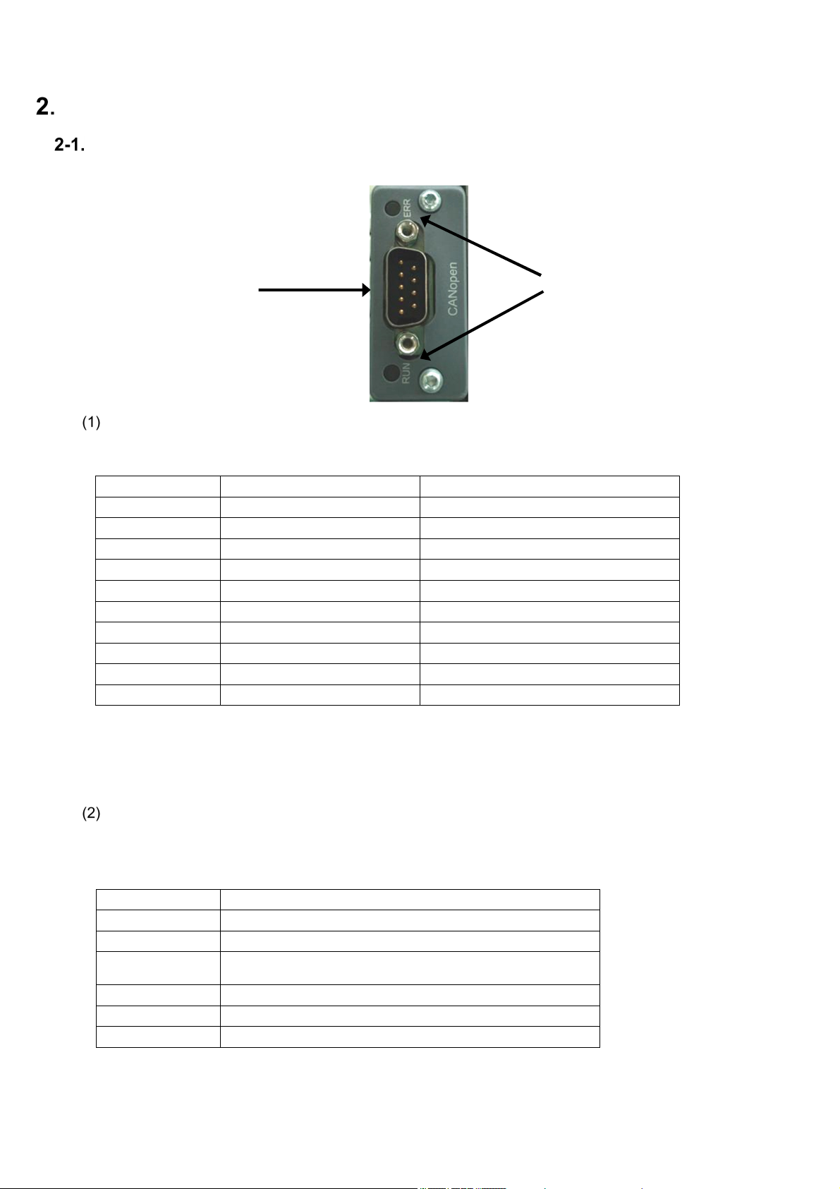
Part Names and Functions .........................................................................................................2
Rear Panel CANopen Interface.............................................................................................................. 2
Connections ................................................................................................................................3
Interface Connector Pin Configuration ................................................................................................... 3
Cable Length ......................................................................................................................................... 3
Wiring precautions ................................................................................................................................. 3
CANopen Communication Settings...........................................................................................4
Switching to Function Mode ................................................................................................................... 4
CANopen Setting Items ......................................................................................................................... 4
Access Sequence........................................................................................................................5
CANopen Object Mapping ..................................................................................................................... 6
Errors...........................................................................................................................................9
Interface Specifications............................................................................................................10
CANopen Interface Specifications ....................................................................................................... 10
Accessories ......................................................................................................................................... 10

1
Overview
This device is a CANopen slave device.
The CANopen interface can be added to the OPT-564 to provide support for CANopen
communication functions (CiA DS301).
Features
The main features of the OPT-564-71 are as follows:
PDO transfer
Supports PDO transmission. Receiving is not supported.
• Torque + rotation speed
• Torque status + rotation speed status
SDO transfer
Supports SDO transfer
• Torque (reading only)
• Rotation speed (reading only)
• Torque status (reading only)
• Rotation speed status (reading only)
• Torque units/decimal place/polarity (reading/writing possible)
• Rotation speed units/decimal place (reading only)
• Rotation speed polarity (reading/writing possible)
• Manufacturer Device Name (reading only)
• Manufacturer Hardware Version (reading only)
• Manufacturer Software Version (reading only)
• PDO transmission interval
CANopen parameter settings
CAN bus address and baud rate can be set.

2
Part Names and Functions
Rear Panel CANopen Interface
Interface connector
This is the CANopen interface connector.
The connector pin configuration is as follows:
Pin No. Signal Details
1 N.C. Not used
2 CAN_L CAN signal Low
3 CAN_GND CAN ground
4 N.C. Not used
5 CAN_SHLD Shield
6 N.C. Not used
7 CAN_H CAN signal High
8 N.C. Not used
9 N.C. Not used
Housing SHIELD Shield
* The connector is not included. Compatible plug: Dedicated CANopen connector
Select a CIA DR-303-1 standard connector.
* Do not connect wires to the N.C. pins.
* Insulated by photocoupler from internal circuit.
Status LEDs
Communication status is indicated by two LEDs.
Defined by DR303-3 (CiA) standard.
RUN LED (green)
Status Description
Off Off
Lit Operation
Continuous
flashing Before operation
Flashes once Stopped
Flickering Automatically detecting baud rate
Lit red Shift to exception status
(2) Status LEDs (1) Interface
connecto
r

3
ERR LED (red)
Status Description
Off Off or operating
Flashes once Error counter has reached or exceeded preset value
Flickering Automatically detecting baud rate
Flashes twice NMT slave or NMT master is detecting Heartbeat event
(Heartbeat consumer)
On Bus off
Connections
Interface Connector Pin Configuration
See "2-1. Rear Panel Interface Connector".
Cable Length
The correlation between baud rate and total distance is as follows:
Baud rate Total distance
10 kbps Up to 1,000 m
20 kbps Up to 1,000 m
50 kbps Up to 1,000 m
100 kbps Up to 600 m
125 kbps Up to 500 m
250 kbps Up to 250 m
500 kbps Up to 100 m
800 kbps Up to 50 m
1 Mbps Up to 25 m
Wiring precautions
Always turn off power before connecting or disconnecting the equipment.
Do not turn on the AC power until all installation work is complete. There is no power ON/OFF switch on
the unit itself.
Keep cables connected to the unit as far away as possible from sources of noise such as power lines or
control interfaces.
Always ground the equipment. Use Type D single grounding. Do not share a ground with the power
supply system.
Turn on the terminal resistance on the CANopen connector farthest from the PLC.
Use a dedicated CANopen cable as the connecting cable.
Select a CiA DR-303-1 compliant connecting cable.

4
CANopen Communication Settings
When using the CANopen interface, configure the following items:
Switching to Function Mode
Function mode can be selected as follows:
1) Hold down the key for 2 seconds.
2) [FUNC] is displayed. Press the key.
3) Confirm the function number to be set.
For details of Function mode settings and operations, see "9. Function Mode" in the OPT-564
Instruction Manual (DRW No. EN294-1924).
CANopen Setting Items
Function No. Item Setting value Details
F-42 Node ID 001 to 127
001
F-43 Baud Rate
0 10 kbps
1 20 kbps
2 50 kbps
3 100 kbps
4 125 kbps
5 250 kbps
6 500 kbps
7 800 kbps
8 1 Mbps
F-45 PDO output interval 0 to 100 0: Off
Units: 1 ms
100
Node ID
Sets the node ID number.
Set in the range 001 to 127.
The default setting is 001.
Baud rate
Sets the baud rate (units: bps).
Select 10 k, 20 k, 50 k, 100 k, 125 k, 250 k, 500 k, 800 k, or 1 M.
The default setting is 1 M.
PDO output interval
Set the PDO output interval (units: 1 msec).
Set in the range 0 to 100. (0: OFF)
The default setting is 100.
The settings take effect only after the power is turned off and then back on again. Turn the power
off and then back on again after the settings have been altered.
To set CANopen objects, load an EDS file.
This can be downloaded from our website (http://www.minebea-mcd.com/) if necessary.

5
Access Sequence
CANopen access is as shown below:
PDO transmission
* (4) PDO transmission is performed only if the data values updated in (2) and (3) have changed.
SDO transmission (SDO reading)
SDO receiving (SDO writing)
Rotation speed
senso
r
Torque sensor
Torque
transducer
System
Software
CAN
Master
device
(4) PDO
transmission
OPT-564
(1) Timer event
(2) Information
acquisition
(3) DPRAM
update
CANbus
CANopen
interface
OPT-564
Rotation speed
senso
r
Torque sensor
Torque
transducer
System
Software (2) Get_Attribute
(3) Information
acquisition
(4) Response transmission (5) SDO
response
(1) SDO upload
CAN
Master
device
CANbus
CANopen
interface
Rotation speed
senso
r
Torque sensor
Torque
transducer
System
Software (2) Set_Attribute
(3) Information
update
(4) Response transmission (5) SDO
response
(1) SDO download
CAN
Master
device
CANbus
OPT-564
CANopen
interface

6
CANopen Object Mapping
Manufacturer Specific Object
Order# Index
(ADI# + 0x2000)
Sub Index
(ADI Element#) Data Type Data
1 0x2001 0x00 SINT32 Torque (*1)
2 0x2002 0x00 SINT32 Rotation speed (*2)
3 0x2011 0x01 UINT32 Torque status (*3)
0x02 UINT32 Rotation speed status (*4)
4 0x2333 0x00 UINT16 Torque units (0: N⋅m/ 1: k N⋅m/ 2: V)
5 0x2334 0x00 UINT16
Torque decimal point position
(0: No decimal point / 1 to 4: Digits after
decimal point)
* Decimal point position is returned as 3
only when the torque units are V and the
decimal point position is 4.
6 0x2335 0x00 UINT16 Torque polarity (135: Counter-clockwise is
+ / 136: Clockwise is +)
7 0x2343 0x00 UINT16 Rotation speed units (1644: fixed at rpm)
8 0x2344 0x00 UINT16 Rotation speed decimal point position
(0: Fixed at no decimal point)
9 0x2345 0x00 UINT16
Rotation speed polarity
(135: Counter-clockwise is + /
136: Clockwise is +)
10 0x2350 0x00 UINT16 PDO transmission interval (ms)
PDO mapping
PDO# Transmission
details
COB-ID
(*5) Tx Type Inhibit
Time
Event
Timer Mapped Objects
1 Torque +
rotation speed
0x180 COS(254) 0 0
0x2001 - 0x00
0x2002 - 0x00
2 Status
0x280 COS(254) 0 0
0x2011 - 0x01
0x2011 - 0x02
If used in the shipped state without changing the configuration, data will be output once from the
COB-ID 0x380+ Device Address and 0x480+ Device Address when a communication start request is
received from the master. This is not output if the configuration has been changed.
(*1). Torque format (SINT32)
0x8000_0000: IN-1 error
0x8000_0001: +OL error
0x8000_0002: -OL error
(*2). Rotation speed format (SINT32)
0x8000_0000: The function F-24 setting is OFF (rotation speed detection signal is off).
0x8000_0001: +OS error
0x8000_0002: -OS error

7
(*3). Torque status format (UINT32)
bit0 (ST):
1: Torque value normal
0: Abnormal value
bit1 (+OL):
1: +OL error / 0: Normal
bit2 (-OL):
1: -OL error / 0: Normal
bit3 (IN-1):
1: IN-1 error / 0: Normal
bit16 (EPR):
1: EEPROM error / 0: Normal
bit17 (CER):
1: PDO communication error / 0: Normal
(*4). Rotation speed status format (UINT32)
bit0 (ST):
1: Rotation speed value normal
0: Abnormal value
bit1 (+OS):
1: +OS error / 0: Normal
bit2 (-OS):
1: -OS error / 0: Normal
bit16 (EPR):
1: EEPROM error / 0: Normal
(*5). The actual COB-ID consists of the value indicated with the device address added.
If configuration has been performed, the COB-ID will be fixed at the value set in the configuration.
ST
07
15 8
1623
31 24
+OL-OL
IN-1
EPRCER
d.c.d.c.
d.c. d.c.
ST
07
15 8
1623
31 24
+OS-OS
EPR
d.c.d.c.
d.c. d.c.

8
SDO mapping
Details CANopen Object Write Notes
Manufacturer Device Name 0x1008 - 0x00 ×
Manufacturer Hardware Version 0x1009 - 0x00 ×
Manufacturer Software Version 0x100A - 0x00 ×
Torque, rotation speed, status See "Manufacturer
Specific Object" ×
Torque units, decimal point
position, polarity
See "Manufacturer
Specific Object"
Rotation speed units, decimal
point position
See "Manufacturer
Specific Object" ×
Rotation speed polarity See "Manufacturer
Specific Object"
PDO transmission interval See "Manufacturer
Specific Object"
* The COB-ID uses the default value (from server: 0x580+Device Address, from client: 0x600+Device
Address).

9
Errors
Error Details
IN-1 error Indicates when no torque signal is input in measurement mode or monitor mode.
+OL error
Indicates when the input torque value exceeds [+110% of maximum display value]
or exceeds 384 kHz in measurement mode. (When 16 kHz is exceeded when F-54
= 0)
-OL error
Indicates when the input torque value is less than [-110% of maximum display
value] or is less than 96 kHz in measurement mode. (When less than 4 kHz when
F-54 = 0)
+OS error Indicates when the rotation speed exceeds 27,500 in measurement mode.
-OS error Indicates when the rotation speed is less than -27,500 in measurement mode.
EEPROM error Indicates when an EEPROM write or read error is detected.
PDO
communication
error
Indicates when a PDO communication error is detected.

10
Interface Specifications
CANopen Interface Specifications
Specifications Details
Baud Rate Select 10 kbps, 20 kbps, 50 kbps, 100 kbps, 125 kbps, 250 kbps, 500 kbps,
800 kbps, or 1 Mbps
Node ID Select within the range 001 to 127
PDO output interval Select within the range 000 to 100 (units: 1 ms)
Cable length Baud rate (bps) Total distance (m)
10 k Up to 1,000
20 k Up to 1,000
50 k Up to 1,000
100 k Up to 600
125 k Up to 500
250 k Up to 250
500 k Up to 100
800 k Up to 50
1 M Up to 25
Connecting cable Use a dedicated CANopen cable.
Connector Use a dedicated CANopen connector.
Termination Use a connector with built-in terminal resistance.
Status LEDs [RUN], [ERR]
Accessories
CANopen instruction
manual ×1


●The contents of this manual may subject to change without notice.
HEAD QUARTER: MinebeaMitsumi Inc.
4106-73 Miyota, Miyota-machi, Kitasaku gun, Nagano-ken 389-0293 Japan
Tel: +81-267-32-2200 Fax: +81-267-31-1350
Sensing Device Product Sales Management:
1-1-1, Katase, Fujisawa-shi, Kanagawa-ken, 251-8531 Japan
Tel: +81-466-23-2681 Fax: +81-466-22-7191
Sensing Device Business Unit
FUJISAWA PLANT 1-1-1, Katase, Fujisawa-shi, Kanagawa-ken, 251-8531 Japan
Tel: +81-466-22-7151 Fax: +81-466-22-1701
KARUIZAWA PLANT 4106-73 Miyota, Miyota-machi, Kitasaku gun, Nagano-ken 389-0293 Japan
Tel: +81-267-31-1309 Fax: +81-267-31-1353
HOMEPAGE ADDRESS http://www.minebea-mcd.com
Table of contents
Other Minebea Transmitter manuals

Minebea
Minebea CSA-524 User manual

Minebea
Minebea CSA-591 User manual

Minebea
Minebea CSA-593 User manual

Minebea
Minebea OPT-564 User manual

Minebea
Minebea CSA-507C User manual

Minebea
Minebea OPT-563B-71 User manual

Minebea
Minebea CSA-528-80-4 User manual

Minebea
Minebea NS100A User manual

Minebea
Minebea CSA-521 User manual

Minebea
Minebea CSA-562B User manual