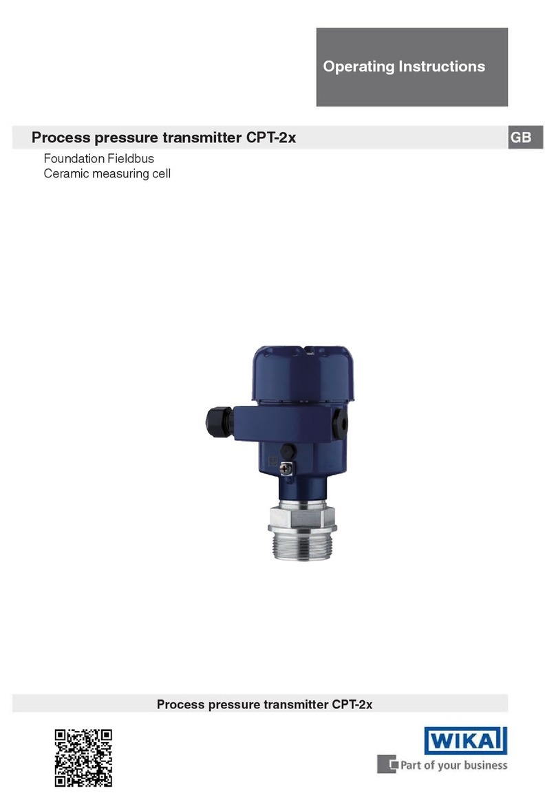
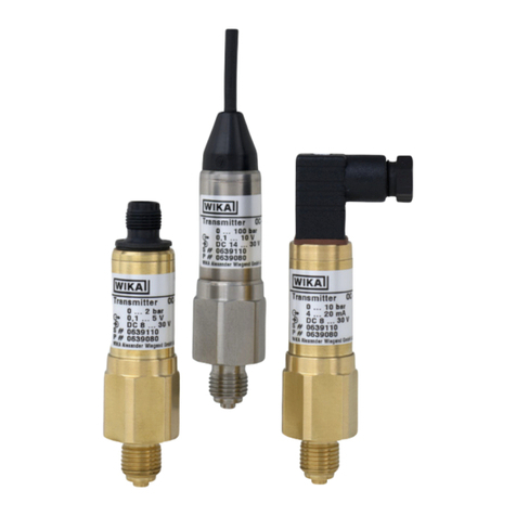
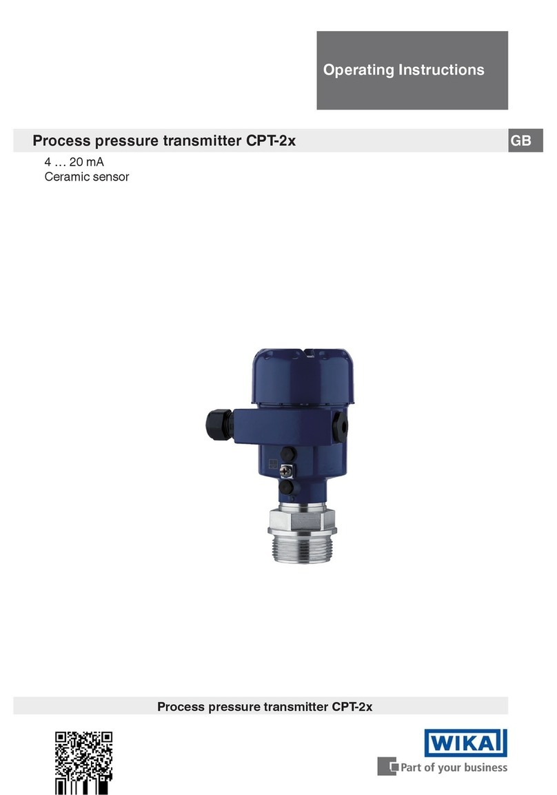
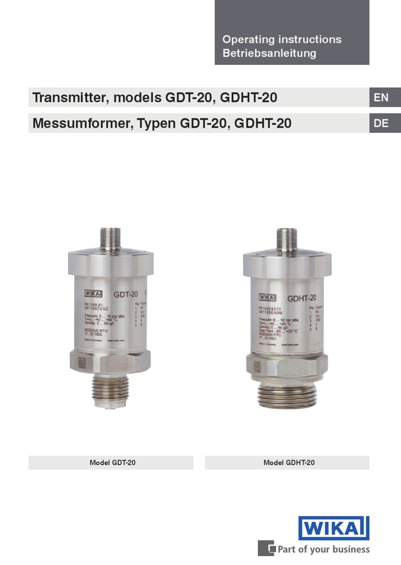
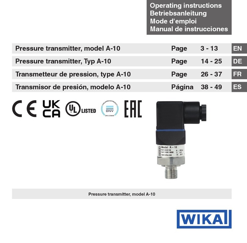
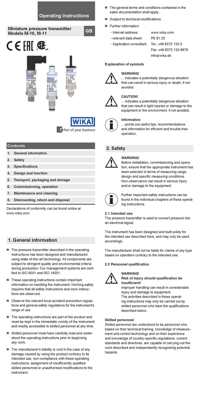
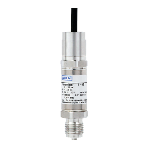
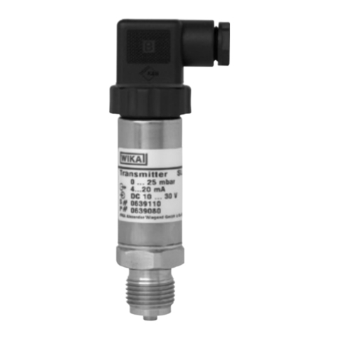
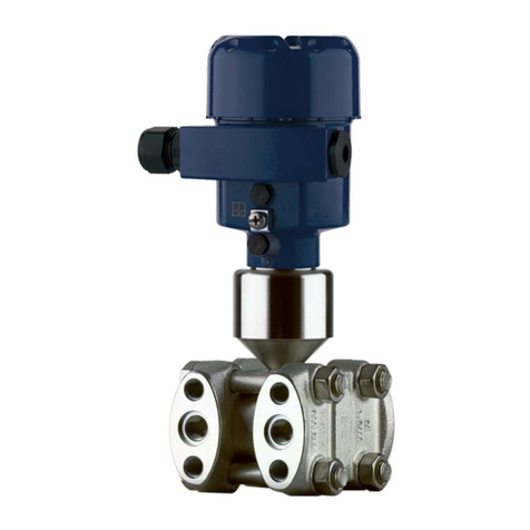
WIKA UPT-20 Installation manual

Additional information
Zusatzinformation
Informations complémentaires
Información adicional
EN
DE
FR
ES
Zusatzinformation für explosionsgefährdete Bereiche
Typen UPT-20 und UPT-21
Plastic version Stainless steel version
Additional information for hazardous areas
Models UPT-20 and UPT-21
Información adicional para zonas potencialmente explosivas
Modelos UPT-20 y UPT-21
Informations complémentaires concernant les zones explosives
Types UPT-20 et UPT-21

2
14381795.02 04/2020 EN/DE/FR/ES
WIKA operating instructions process transmitter, model UPT-2x
EN
DE
FR
ES
© 12/2019 WIKA Alexander Wiegand SE & Co. KG
All rights reserved. / Alle Rechte vorbehalten.
WIKA®is a registered trademark in various countries.
WIKA®ist eine geschützte Marke in verschiedenen Ländern.
Prior to starting any work, read the operating instructions!
Keep for later use!
Vor Beginn aller Arbeiten Betriebsanleitung lesen!
Zum späteren Gebrauch aufbewahren!
Lire le mode d‘emploi avant de commencer toute opération !
A conserver pour une utilisation ultérieure !
¡Leer el manual de instrucciones antes de comenzar cualquier trabajo!
¡Guardar el manual para una eventual consulta!
Zusatzinformation
Typ UPT-2x Seite 9 - 16
Additional information
Model UPT-2x Page 3 - 8
Información adicional
Modelo UPT-2x Página 25 - 31
Informations complémentaires
Type UPT-2x Page 17 - 24

3WIKA operating instructions process transmitter, model UPT-2x
EN
14381795.02 04/2020 EN/DE/FR/ES
Contents
Contents
Declarations of conformity can be found online at www.wika.com
1. Ex marking 4
2. Safety 5
3. Commissioning 6
4. Special conditions for safe use (X-conditions) 7
5. Dismounting 7
6. Specifications 7
Appendix: EU declaration of conformity 8

4WIKA operating instructions process transmitter, model UPT-2x
EN
14381795.02 04/2020 EN/DE/FR/ES
Supplementary documentation:
▶
This additional information for hazardous areas applies in conjunction with the
operating instructions „Process transmitter, model UPT-2x“ (article number 14068347).
1. Ex marking
1. Ex marking
DANGER!
Danger to life due to loss of explosion protection
Non-observance of these instructions and their contents may result in the
loss of explosion protection.
▶
Observe the safety instructions in this chapter and further explosion
instructions in these operating instructions.
▶
Observe the information given in the applicable Ex certificate and the
relevant regulations for installation and use in hazardous areas.
Check whether the classication is suitable for the application. Observe the relevant
national regulations.
Approval Marking
ATEX Zone 1 gas
Zone 1 mounting to zone 0 gas
Zone 2 gas
Zone 21 dust
Zone 21 mounting to zone 20 dust
[II 2G Ex ia IIC T4/T5/T6 Gb]
[II 1/2G Ex ia IIC T4/T5/T6 Ga/Gb]
[II 3G Ex ic IIC T4/T5/T6 Gc]
[II 2D Ex ia IIIC T135 °C Db]
[II 1/2D Ex ia IIIC T135 °C Da/Db]
IECEx Zone 1 gas
Zone 1 mounting to zone 0 gas
Zone 2 gas
Zone 21 dust
Zone 21 mounting to zone 20 dust
[Ex ia IIC T6 ...T3 Gb]
[Ex ia IIC T6 ...T3 Ga/Gb]
[Ex ia IIC T6 ...T3 Gc]
[Ex ia IIIC T135 °C Db]
[Ex ia IIIC T135 °C Da/Db]
Approval ratings ATEX and IECEx
■
Gases and mist Mounting to zone 0 (EPL Ga/Gb)
Installation in zone 1 (EPL Gb) and zone 2 (EPL Gc)
■
Dusts Mounting to zone 20 (EPL Da/Db); installation in zone 21 (EPL Db)
For further certicates and approvals, see local website.

5WIKA operating instructions process transmitter, model UPT-2x
EN
14381795.02 04/2020 EN/DE/FR/ES
2. Safety
2. Safety
2.1 Explanation of symbols
DANGER!
... indicates a potentially dangerous situation in the hazardous area that can
result in serious injury or death, if not avoided.
2.2 Intended use
Process transmitter approved for use in hazardous areas, type tested in accordance
with the following standards:
IEC 60079-0:2011 + Corr.1:2012 + Corr.2:2013 / EN 60079-0:2012 + A11:2013
IEC 60079-11:2011 + Corr.1:2012 / EN 60079-11:2012
IEC 60079-26:2015 / EN 60079-26:2015
2.3 Responsibility of the operator
The responsibility for classication of zones lies with the plant operator and not the
manufacturer/supplier of the equipment.
2.4 Personnel qualication
Special knowledge for working with instruments for hazardous areas
The skilled personnel must have knowledge of ignition protection types, regulations and
provisions for equipment in hazardous areas.
2.5 Risks in hazardous areas
Observe the information given in the type examination certicate and the country-specic
regulations for installation and use in hazardous areas (e.g. IEC 60079-14, NEC, CEC). If
this is not observed, serious injuries and damage could occur.
Do not commission any damaged instruments within hazardous areas. Damaged instru-
ments cannot reliably guarantee any explosion protection. Obvious damage must be
reported immediately.
2.6 Labelling, safety marks
Product label
Approval ratings

6WIKA operating instructions process transmitter, model UPT-2x
EN
14381795.02 04/2020 EN/DE/FR/ES
3. Commissioning
The process transmitter should only be commissioned and operated by skilled personnel.
The skilled personnel must have knowledge of ignition protection types, regulations and
provisions for equipment in hazardous areas.
DANGER!
Danger to life from explosion
Incorrect mounting and non-compliance with the contents of this chapter
can lead to a risk of explosion.
▶
Carefully read and comply with the following sub-chapters.
3.1 Mounting the process transmitter
DANGER!
Damaged diaphragm of the ush process connection
If the diaphragm is damaged, the explosion protection is no longer guaranteed.
Through any explosion resulting from this, there will be a high danger to life.
▶
Before commissioning, the diaphragm should be checked for visible
damage. Leaking fluid is indicative of damage.
▶
Protect the diaphragm from contact with abrasive media and against any
impacts.
3.2 Electrical installation
DANGER!
Danger to life from explosion
Incorrect mounting and non-compliance with the contents of this chapter
can lead to a risk of explosion.
▶
Carefully read and comply with the following sub-chapters.
Observe the information given in the type examination certicate and the country-specic
regulations for installation and use in hazardous areas (e.g. IEC 60079-14, NEC, CEC)
. If
this is not observed, serious injuries and damage could occur.
→ Type examination certicate is available for download at www.wika.com.
3.2.1 Requirements regarding intrinsic voltage supply
■
Power the process transmitter via an intrinsically safe circuit (Ex ia). Both the internal
capacitance and inductance must be considered (→ see chapter 6 “Specications”).
■
Provide the required voltage supply separation between Ex and non-Ex areas with a
certied isolated barrier or Zener barrier (suitable isolated barrier, model IS-Barrier).
■
For applications that require EPL Gb or Db, the power sup
ply and signal circuit should
have a protection level of “ib”. Then the interconnections and the transmitter will have
a protection level of II 2G Ex ib IIC T4/T5/T6 Gb or II 2D Ex ib IIIC T4/T5/T6 Db, even if
the process transmitter is marked otherwise (→ see EN 60079-14 section 5.4).
3. Commissioning
7WIKA operating instructions process transmitter, model UPT-2x
EN
14381795.02 04/2020 EN/DE/FR/ES
4. Special conditions for safe use (X-conditions)
For the case “mounting to zone 0 (EPL Ga/Gb)”
The instrument’s internal separation (diaphragm) from the wetted area has a wall thick-
ness of < 0.2 mm in order to ensure proper functioning. In operation, it must be ensured
that any impairment of the separation, e.g. by aggressive media or through mechanical
damage, is eliminated.
5. Dismounting
Observe the information given in the type examination certicate and the country-specic
regulations for installation and use in hazardous areas (e.g. IEC 60079-14, NEC, CEC)
. If
this is not observed, serious injuries and damage could occur.
6. Specications
Permissible temperature ranges
Temperature classes/surface temperatures for all variants except for
UPT-2*-*I*-**-**-*****-*4****-** (model without cooling element):
Temperature class/surface temperature Ambient and medium temperature (°C)
T5, T6 -40 ≤ Ta ≤ +60
T4 -40 ≤ Ta ≤ +80
T135 °C -40 ≤ Ta ≤ +40 for Pi = 750 mW
-40 ≤ Ta ≤ +70 for Pi = 650 mW
-40 ≤ Ta ≤ +80 for Pi = 550 mW
Temperature classes/surface temperatures only for variant
UPT-2*-*I*-**-**-*****-*4****-** (model with cooling element):
Temperature class Max. medium temperature (°C)
Ambient temperature (°C)
T4 120 -40 ≤ Ta ≤ +50
T3 150 -40 ≤ Ta ≤ +40
Restrictions to temperature ranges
Medium temperature
Gas hazardous application Temperature class (maximum ambient
temperature)
Dust hazardous application maximum output values of the current supply
(EN/IEC 60079-11, section 5.6.5).
4. Special conditions for ... /5. .../6. Specications

8WIKA operating instructions process transmitter, model UPT-2x
EN
14381795.02 04/2020 EN/DE/FR/ES
Appendix: EU declaration of conformity

9WIKA Betriebsanleitung Prozesstransmitter, Typ UPT-2x
DE
14381795.02 04/2020 EN/DE/FR/ES
Inhalt
Konformitätserklärungen nden Sie online unter www.wika.de.
1. Ex-Kennzeichnung 10
2. Sicherheit 11
3. Inbetriebnahme 12
4. Besondere Bedingungen für den sicheren Betrieb 13
5. Demontage 13
6. Technische Daten 14
Anlage 1: EG-Konformitätserklärung Typ UPT-2x 15
Inhalt

10 WIKA Betriebsanleitung Prozesstransmitter, Typ UPT-2x
DE
14381795.02 04/2020 EN/DE/FR/ES
Ergänzende Dokumentation:
▶
Diese Zusatzinformation für explosionsgefährdete Bereiche gilt im Zusammenhang mit
der Betriebsanleitung „Prozesstransmitter, Typ UPT-2x“ (Artikelnummer 14068347).
1. Ex-Kennzeichnung
1. Ex-Kennzeichnung
GEFAHR!
Lebensgefahr durch Verlust des Explosionsschutzes
Die Nichtbeachtung dieser Inhalte und Anweisungen kann zum Verlust des
Explosionsschutzes führen.
▶
Sicherheitshinweise in diesem Kapitel sowie weitere Explosionshinweise
in dieser Betriebsanleitung beachten.
▶
Die Angaben der geltenden Ex-Zertifikate sowie die jeweiligen Vorschrif-
ten zur Installation und Einsatz in explosionsgefährdeten Bereichen
einhalten.
Überprüfen, ob die Klassizierung für den Einsatzfall geeignet ist. Die jeweiligen natio-
nalen Vorschriften und Bestimmungen beachten.
Zulassung Kennzeichnung
ATEX Zone 1 Gas
Zone 1 Anbau an Zone 0 Gas
Zone 2 Gas
Zone 21 Staub
Zone 21 Anbau an Zone 20 Staub
[II 2G Ex ia IIC T4/T5/T6 Gb]
[II 1/2G Ex ia IIC T4/T5/T6 Ga/Gb]
[II 3G Ex ic IIC T4/T5/T6 Gc]
[II 2D Ex ia IIIC T135 °C Db]
[II 1/2D Ex ia IIIC T135 °C Da/Db]
IECEx Zone 1 Gas
Zone 1 Anbau an Zone 0 Gas
Zone 2 Gas
Zone 21 Staub
Zone 21 Anbau an Zone 20 Staub
[Ex ia IIC T6 ...T3 Gb]
[Ex ia IIC T6 ...T3 Ga/Gb]
[Ex ia IIC T6 ...T3 Gc]
[Ex ia IIIC T135 °C Db]
[Ex ia IIIC T135 °C Da/Db]
Zulassungseigenschaften ATEX und IECEx
■
Gase und Nebel Anbau an Zone 0 (EPL Ga/Gb)
Einbau in Zone 1 (EPL Gb) und Zone 2 (EPL Gc)
■
Stäube Anbau an Zone 20 (EPL Da/Db); Einbau in Zone 21 (EPL Db)
Weitere Zulassungen und Zertikate siehe lokale Internetseite.

11WIKA Betriebsanleitung Prozesstransmitter, Typ UPT-2x
DE
14381795.02 04/2020 EN/DE/FR/ES
2. Sicherheit
2.1 Symbolerklärung
GEFAHR!
... weist auf eine möglicherweise gefährliche Situation im explosionsgefähr-
deten Bereich hin, die zum Tod oder zu schweren Verletzungen führen kann,
wenn sie nicht gemieden wird.
2.2 Bestimmungsgemäße Verwendung
Prozesstransmitter zur bestimmungsgemäßen Verwendung in explosionsgefährdeten
Bereichen, bauartgeprüft nach folgenden Normen:
IEC 60079-0:2011 + Corr.1:2012 + Corr.2:2013 / EN 60079-0:2012 + A11:2013
IEC 60079-11:2011 + Corr.1:2012 / EN 60079-11:2012
IEC 60079-26:2015 / EN 60079-26:2015
2.3 Verantwortung des Betreibers
Die Verantwortung über die Zoneneinteilung unterliegt dem Anlagenbetreiber und nicht
dem Hersteller/Lieferanten der Betriebsmittel.
2.4 Personalqualikation
Besondere Kenntnisse bei Arbeiten mit Geräten für explosionsgefährdete
Bereiche
Das Fachpersonal muss Kenntnisse haben über Zündschutzarten, Vorschriften und
Verordnungen für Betriebsmittel in explosionsgefährdeten Bereichen.
2.5 Gefahren in explosionsgefährdeten Bereichen
Die Angaben der Baumusterprüfbescheinigung und die landesspezischen Vorschrif-
ten zur Installation und Einsatz in explosionsgefährdeten Bereichen einhalten (z. B.
IEC 60079-14, NEC, CEC). Werden diese nicht eingehalten, können schwere Körper-
verletzungen und Sachschäden entstehen.
Keine beschädigten Geräte in explosionsgefährdeten Bereichen in Betrieb nehmen.
Beschädigte Geräte gewährleisten keinen zuverlässigen Explosionsschutz. Oensichtli-
che Schäden unverzüglich mitteilen.
2. Sicherheit

12 WIKA Betriebsanleitung Prozesstransmitter, Typ UPT-2x
DE
14381795.02 04/2020 EN/DE/FR/ES
2.6 Beschilderung, Sicherheitskennzeichnungen
Typenschild
Zulassungseigenschaften
3. Inbetriebnahme
Prozesstransmitter nur durch Fachpersonal in Betrieb nehmen und betreiben.
Das Fachpersonal muss Kenntnisse haben über Zündschutzarten, Vorschriften und
Verordnungen für Betriebsmittel in explosionsgefährdeten Bereichen.
GEFAHR!
Lebensgefahr durch Explosion
Bei fehlerhafter Montage und Nichtbeachten der Inhalte dieses Kapitels
besteht Explosionsgefahr.
▶
Folgende Unterkapitel aufmerksam lesen und einhalten.
3.1 Prozesstransmitter montieren
GEFAHR!
Beschädigte Membrane des frontbündigen Prozessanschlusses
Bei einer beschädigten Membrane ist der Explosionsschutz nicht mehr
gewährleistet. Durch eine daraus resultierende Explosion besteht höchste
Lebensgefahr.
▶
Vor Inbetriebnahme die Membrane optisch auf Beschädigungen überprü-
fen. Auslaufende Flüssigkeit weist auf eine Beschädigung hin.
▶
Die Membrane vor Kontakt mit abrasiven Messstoffen und gegen Schläge
schützen.
3.2 Elektrische Installation
GEFAHR!
Lebensgefahr durch Explosion
Bei fehlerhafter Montage und Nichtbeachten der Inhalte dieses Kapitels
besteht Explosionsgefahr.
▶
Folgende Unterkapitel aufmerksam lesen und einhalten.
2. Sicherheit/3. Inbetriebnahme

13WIKA Betriebsanleitung Prozesstransmitter, Typ UPT-2x
DE
14381795.02 04/2020 EN/DE/FR/ES
Die Angaben der Baumusterprüfbescheinigung und die landesspezischen Vorschrif-
ten zur Installation und Einsatz in explosionsgefährdeten Bereichen einhalten (z. B.
IEC 60079-14, NEC, CEC). Werden diese nicht eingehalten, können schwere Körper-
verletzungen und Sachschäden entstehen.
→ Baumusterprüfbescheinigung steht unter www.wika.de zum Download bereit.
3.2.1 Anforderungen an eigensichere Spannungsversorgung
■
Den Prozesstransmitter aus einem eigensicheren Stromkreis (Ex ia) versorgen. Die
innere wirksame Kapazität und Induktivität beachten (→ siehe Kapitel 6 „Technische
Daten“).
■
Die nötige Trennung der Spannungsversorgung zwischen Ex- und Nicht-Ex-Bereich
mit einer bescheinigten Trennbarriere oder Zenerbarriere herstellen. (Geeignete
Trennbarriere Typ IS-Barrier)
■
Bei Anwendungen, die einen EPL Gb oder Db erfordern, darf der Versorgungs-
und Signalstromkreis das Schutzniveau „ib“ haben. Dann besitzt die Zusammen-
schaltung und der Transmitter das Schutzniveau II 2G Ex ib IIC T4/T5/T6 Gb oder
II 2D Ex ib IIIC T4/T5/T6 Db, auch wenn der Prozesstransmitter anders gekennzeich-
net ist (→ siehe EN 60079-14 Abschnitt 5.4)
4. Besondere Bedingungen für den sicheren Betrieb
Für den Fall „Anbau an Zone 0 (EPL Ga/Gb)“
Die geräteinterne Trennwand (Membrane) zum medienberührten Bereich weist funkti-
onsbedingt eine Wandstärke < 0,2 mm auf. In der Verwendung ist sicherzustellen, dass
eine Beeinträchtigung der Trennwand z. B. durch aggressive Medien oder durch mecha-
nische Gefährdungen ausgeschlossen wird.
5. Demontage
Die Angaben der Baumusterprüfbescheinigung und die landesspezischen Vorschrif-
ten zur Installation und Einsatz in explosionsgefährdeten Bereichen einhalten (z. B.
IEC 60079-14, NEC, CEC). Werden diese nicht eingehalten, können schwere Körper-
verletzungen und Sachschäden entstehen.
3. Inbetriebnahme/4. .../5. Demontage

14 WIKA Betriebsanleitung Prozesstransmitter, Typ UPT-2x
DE
14381795.02 04/2020 EN/DE/FR/ES
6. Technische Daten
Zulässige Temperaturbereiche
Temperaturklassen/Oberächentemperaturen für alle Varianten außer
UPT-2*-*I*-**-**-*****-*4****-** (Modell mit Kühlelement):
Temperaturklasse/Oberächentemperatur Umgebungs- und Messstotemperatur (°C)
T5, T6 -40 ≤ Ta ≤ +60
T4 -40 ≤ Ta ≤ +80
T135 °C -40 ≤ Ta ≤ +40 für Pi = 750 mW
-40 ≤ Ta ≤ +70 für Pi = 650 mW
-40 ≤ Ta ≤ +80 für Pi = 550 mW
Temperaturklassen/Oberächentemperaturen nur für Variante
UPT-2*-*I*-**-**-*****-*4****-** (Modell mit Kühlelement):
Temperaturklasse Max. Messstotemperatur (°C)
Umgebungstemperatur (°C)
T4 120 -40 ≤ Ta ≤ +50
T3 150 -40 ≤ Ta ≤ +40
Einschränkungen der Temperaturbereiche
Messstotemperatur
Gas-Ex-Anwendung Temperaturklasse (maximale Umgebungstem-
peratur)
Staub-Ex-Anwendung Maximale Ausgangswerte der Stromversorgung
(EN/IEC 60079-11, Abschnitt 5.6.5).
6. Technische Daten

15WIKA Betriebsanleitung Prozesstransmitter, Typ UPT-2x
DE
14381795.02 04/2020 EN/DE/FR/ES
Anlage 1: EG-Konformitätserklärung Typ UPT-2x

16 WIKA operating instructions process transmitter, model UPT-2x
14381795.02 04/2020 EN/DE/FR/ES

17WIKA mode d'emploi transmetteur de process, type UPT-2x
FR
14381795.02 04/2020 EN/DE/FR/ES
Sommaire
Sommaire
Déclarations de conformité disponibles en ligne sur www.wika.com
1. Marquage Ex 18
2. Sécurité 19
3. Mise en service 20
4. Conditions spéciques pour une utilisation sûre (conditions X) 21
5. Démontage 21
6. Spécications 22
Annexe : Déclaration de conformité UE 23

18 WIKA mode d'emploi transmetteur de process, type UPT-2x
FR
14381795.02 04/2020 EN/DE/FR/ES
Documentation supplémentaire :
▶
Ces informations complémentaires concernant les zones explosives s'appliquent
en combinaison avec le mode d'emploi “Transmetteur de process, type UPT-2x”
(numéro d'article 14068347).
1. Marquage Ex
1. Marquage Ex
DANGER !
Danger de mort dû à la perte de la protection contre les explosions
Le non-respect de ces instructions et de leurs contenus peut entraîner
une perte de la protection contre les explosions.
▶
Observer les instructions de sécurité de ce chapitre et les autres instruc-
tions liées aux explosions de ce mode d'emploi.
▶
Respecter les indications du certificat Ex de même que les prescriptions
respectives concernant le montage et l'utilisation en zone explosive.
Contrôler que la classication est adaptée à l'application. Observer les réglementations
nationales concernées.
Homologation Marquage
ATEX Zone 1 gaz
Zone 1 pour installation dans zone 0 gaz
Zone 2 gaz
Zone 21 poussière
Zone 21 pour installation dans zone 20
poussière
[II 2G Ex ia IIC T4/T5/T6 Gb]
[II 1/2G Ex ia IIC T4/T5/T6 Ga/Gb]
[II 3G Ex ic IIC T4/T5/T6 Gc]
[II 2D Ex ia IIIC T135 °C Db]
[II 1/2D Ex ia IIIC T135 °C Da/Db]
IECEx Zone 1 gaz
Zone 1 pour installation dans zone 0 gaz
Zone 2 gaz
Zone 21 poussière
Zone 21 pour installation dans zone 20
poussière
[Ex ia IIC T6 ...T3 Gb]
[Ex ia IIC T6 ...T3 Ga/Gb]
[Ex ia IIC T6 ...T3 Gc]
[Ex ia IIIC T135 °C Db]
[Ex ia IIIC T135 °C Da/Db]
Agréments ATEX et IECEx
■
Gaz et brouillard Installation en zone 0 (EPL Ga/Gb)
Installation en zone 1 (EPL Gb) et zone 2 (EPL Gc)
■
Poussières Installation en zone 20 (EPL Da/Db) ; installation en zone 21
(EPL Db)
Pour plus de certicats et d'agréments, voir site web local.

19WIKA mode d'emploi transmetteur de process, type UPT-2x
FR
14381795.02 04/2020 EN/DE/FR/ES
2. Sécurité
2. Sécurité
2.1 Explication des symboles
DANGER !
... indique une situation en zone explosive présentant des risques susceptib-
les de provoquer la mort ou des blessures graves si elle n'est pas évitée.
2.2 Utilisation conforme à l'usage prévu
Transmetteur de process homologué pour un usage en zone explosive, type testé en
conformité avec les normes suivantes :
IEC 60079-0:2011 + Corr.1:2012 + Corr.2:2013 / EN 60079-0:2012 + A11:2013
IEC 60079-11:2011 + Corr.1:2012 / EN 60079-11:2012
CEI 60079-26:2015 / EN 60079-26:2015
2.3 Responsabilité de l'opérateur
La classication des zones est une responsabilité qui incombe à l'exploitant du site et
non au fabricant/fournisseur de l'équipement.
2.4 Qualication du personnel
Connaissances spéciques pour l'utilisation des instruments en zone explosive
Le personnel qualié doit avoir les connaissances requises des types de protection
contre l'ignition, des règlementations et dispositions concernant les équipements en
zones explosives.
2.5 Risques en zones explosives
Respecter les indications du certicat d'examen de type de même que les prescriptions
nationales respectives concernant le montage et l'utilisation en zone explosive (par
exemple CEI 60079-14, NEC, CEC). Un non-respect de ces consignes peut entraîner
des blessures corporelles graves et des dégâts matériels.
Ne pas mettre en service des instruments endommagés en zone explosive. Des instru-
ments endommagés ne peuvent garantir aucune protection contre l'explosion. Commu-
niquer immédiatement les dégâts constatés.
2.6 Etiquetage, marquages de sécurité
Plaque signalétique
Agréments

20 WIKA mode d'emploi transmetteur de process, type UPT-2x
FR
14381795.02 04/2020 EN/DE/FR/ES
3. Mise en service
Le transmetteur de process ne doit être mis en service et exploité que par du personnel
qualié.
Le personnel qualié doit avoir les connaissances requises des types de protection
contre l'ignition, des règlementations et dispositions concernant les équipements en
zones explosives.
DANGER !
Danger d'explosion mortelle
Une installation incorrecte et le non-respect du contenu de ce chapitre
peuvent conduire à un risque d'explosion.
▶
Lire attentivement et exécuter les sous-chapitres suivants.
3.1 Installation du transmetteur de process
DANGER !
Membrane endommagée du raccord process aeurant
Si la membrane est endommagée, la protection contre l'explosion n'est plus
garantie.Une explosion résultant de ceci représente un danger mortel.
▶
Avant la mise en service, il faut vérifier la membrane pour voir si elle ne
présente aucun dommage visible. Une fuite de liquide indique un dommage.
▶
Protéger la membrane du contact avec des fluides abrasifs et contre tout
impact.
3.2 Installation électrique
DANGER !
Danger d'explosion mortelle
Une installation incorrecte et le non-respect du contenu de ce chapitre
peuvent conduire à un risque d'explosion.
▶
Lire attentivement et exécuter les sous-chapitres suivants.
Respecter les indications du certicat d'examen de type de même que les prescriptions
nationales respectives concernant le montage et l'utilisation en zone explosive (par
exemple CEI 60079-14, NEC, CEC)
. Un non-respect de ces consignes peut entraîner
des blessures corporelles graves et des dégâts matériels.
→ Le certicat d'examen de type est disponible pour téléchargement sur www.wika.com.
3. Mise en service
Other manuals for UPT-20
2
This manual suits for next models
1
Table of contents
Languages:
Other WIKA Transmitter manuals
Popular Transmitter manuals by other brands

TeknikSat Satellite Systems
TeknikSat Satellite Systems TPF 11-2 user guide

Williams Sound
Williams Sound Hearing Helper T800 Manual and user guide

Auto Mate
Auto Mate 7142A quick start guide

Crestron
Crestron DM-TX-401-C quick start guide

Intelix
Intelix AvoCat AVO-SVA2-WP-F Series installation manual

Audio Technica
Audio Technica ATW-T1006 Installation and operation