Mobeye PowerGuard CM2100 User manual

USER MANUAL
Mobeye®PowerGuard
CM2100
SW version 4.n


CONTENT
1. General description 2
2. Getting started 3
2.1 Insert a SIM card 3
2.2 Insert the batteries 3
2.3 Connect an external power supply 4
2.4 Program at least one telephone number 4
2.5 Switching on/off 5
2.6 Confirmation of the alarm message 5
3. Connect sensors to the inputs 6
4. Configuration 7
4.1 Program mode 7
4.2 The (security) code 8
4.3 Programming the settings by SMS 8
4.4 List of SMS commands for configuration 9
5. Possible settings 11
5.1 Phone numbers 11
5.2 Identification text 11
5.3 Alarm texts 12
5.4 SMS on/off 12
5.5 Call on/off 12
5.6 Input type 13
5.7 Exit delay time 13
5.8 Alarm delay time 13
5.9 Inactive time 14
5.10 Alarm repeat time 14
5.11 Power failure delay time 14
5.12 Power failure message 15
5.13 Automatic arming / disarming 15
5.14 Buttonlock 16
5.15 Low power mode 17
5.16 Test message 17
5.17 System reset 17
6. Request list of the status, settings and signal strength 18
7. Mobeye Internet Portal 19
8. Technical messages and status feedback 20

1
Attention! Very important
This user manual contains important guidelines for the installation and usage of the Mobeye®
device as described in this manual. Please read these thoroughly before you start using the
Mobeye® device.
In case of damage caused by disregarding the guidelines, the warranty becomes void.
The user must regularly check the proper functioning of the device. The manufacturer cannot
be held liable for any damage or loss caused by any incorrect use or incorrect functioning of
the Mobeye® device.
Safety guidelines
• The permitted ambient temperature during operation may not be exceeded (not lower
than -10°C and not higher than 50°C).
• The device is intended for use in dry and clean places.
• Protect the device from moisture, heat and water splashing. Not intended for external use.
• The guidelines for the battery usage must be regarded.
• Do not expose the device to strong vibrations.
• Do not let it fall from height.
• Do not use in an environment where any inflammable gases, vapors or dust are present
or could be present.
• Repair of the device may only be carried out by people, trained for Mobeye®repair.
• If the device must be repaired, only original replacement components may be used. The
use of different parts may lead to damage of the Mobeye®device.
Use in accordance with the regulations
The purpose of this device in accordance with the regulations is sending SMS text messages
and making telephone calls after an alarm situation. Other uses are not permitted and may
invalidate the warranty.
Battery recycling
CR123 batteries, as used in the Mobeye PowerGuard, are classified as non-hazardous waste
and can be recycled. Please take empty batteries to a nearest collection point.

2
1. GENERAL DESCRIPTION
The Mobeye PowerGuard is a battery operated GSM module used to send an alarm
notification after power failure or after a triggered input.
The factory settings of the Mobeye PowerGuard cause following reactions:
- When a power failure occurs, the Mobeye PowerGuard sends an alarm SMS text
message and calls the phone numbers programmed in by the user.
- When the power is restored, the Mobeye PowerGuard sends a ‘power restored’
SMS text message.
- When one of the inputs is activated by a sensor, the Mobeye PowerGuard sends
an alarm SMS text message and calls the phone numbers programmed in by the
user.
- When one of the inputs remain in the alarm status, the Mobeye PowerGuard
repeats sending the SMS alarm message every four hours.
- When the batteries need to be replaced, the Mobeye PowerGuard sends a ‘low
battery’SMS text message to the first telephone number (administrator).
The Mobeye PowerGuard has many options to influence the behaviour, which are
described in chapter 4. For additional alarm and monitoring functions the Mobeye
PowerGuard can be connected to the Mobeye Internet Portal, which is explained in
chapter 7.

3
2. GETTING STARTED
To get started with the Mobeye PowerGuard, at least the following steps need to be
taken in the following order:
1. Insert a SIM card
2. Insert the batteries
3. Connect an external power supply
4. Program at least one telephone number
5. Arming/disarming the system
These steps are further explained in this chapter. After these steps the module will be
operational.
2.1 INSERT A SIM CARD
Open the enclosure by removing the 4 screws and insert a SIM card into the module.
Push the black cover slightly outward to open the holder. Before installing the SIM
card should have PIN code "0000", or PIN code removed.
(A PIN code can be changed or removed by putting the SIM card in to any mobile phone and entering
the 'security' menu).
NB: Make sure the SIM card is inserted before the batteries are inserted. If you
replace a SIM card, first remove the batteries (and remove any other external power
supply). The settings are stored in the device memory. The SIM card shall have the
“normal” size and be suitable for 2G. It is advised to use an M2M SIM card.
2.2 INSERT THE BATTERIES
Insert the two batteries (CR123) in the module. Use the +/- indication for the correct
placement.

4
2.3 CONNECT AN EXTERNAL POWER SUPPLY
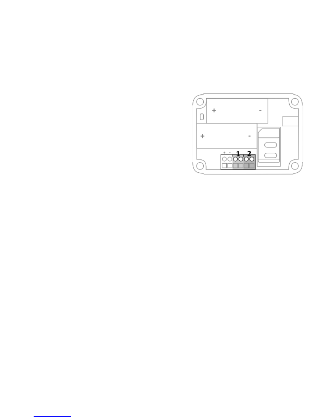
Connect the external power adapter (or any
other regulated 12VDC power supply) to the
power input of the connector (press on the
green pins to connect the wires):
- V+ (black lead with white stripe) to “+”
- Ground (black lead) to “-“
As soon as the batteries are placed and the power source is connected, the Mobeye
PowerGuard switches to the program mode. First the GSM module establishes
network connection. During this time the LED flashes green and red. Within 10-30
seconds the connection is established and the status LED starts flashing 1 sec. on/1
sec. off (or stays on continuously in case the first telephone number has been
configured).
2.4 PROGRAM AT LEAST ONE TELEPHONE NUMBER
The Mobeye PowerGuard is able to send messages up to 5 telephone numbers. The
first telephone number (TEL1) belongs to the administrator. Technical messages (such
as battery low) are sent to the administrator only. Without the administrators’phone
number, the Mobeye PowerGuard cannot function.
When the PowerGuard is in initial (factory) status and the batteries are inserted (so the
LED is flashing), the administrators’number is programmed by calling the telephone
number of the Mobeye PowerGuard using the administrators’ phone. The unit will
recognize this number and store it as administrator (TEL1). The administrator will
receive a confirmation SMS text message including the security code. This code is
needed to program the other settings in the unit.
NB: For this way of programming the number recognition in the administrator’s phone
must be ‘on’. To program or change the administrators’ number by SMS command,
please refer to 4.2.

5
2.5 SWITCHING ON/OFF
After the previous steps, the Mobeye PowerGuard is ready for use. It is armed
(switched on) automatically.
In order to switch off (disarm) the Mobeye PowerGuard:
- Press the on/ off button at the upper side for 1 second. The green LED switches off
to indicate the disarmed status.
In the disarmed status the Mobeye PowerGuard will not send alarm notifications.
The functions automatic arming and sending a ‘low battery’message, are still
active.
In order to switch on (arm) the Mobeye PowerGuard:
- Press the on/ off button at the upper side for 1 second. The green LED blinks once
every 3 seconds (battery-powered) or stays ‘on’ continuously (in case of an
external power supply).
If powered externally (GSM is open), switching can be done via SMS commands:
SMS-command to switch on: CODE ARM
SMS-command to switch off: CODE DISARM
example: 1111 ARM
The status can be requested via SMS command CODE STATUS? (see chapter 6).
2.6 CONFIRMATION OF THE ALARM MESSAGE
When the system is triggered it will send alarm notifications. First an SMS text
message is sent to all programmed alarm numbers, followed by a phone call. When
you pick up the phone, you will hear beeps. It is possible to confirm the phone call by
answering the phone and pressing any key. The other alarm numbers will not be
called afterwards.
By switching off the ‘SMS’ function, the system will only call. This prevents the other
numbers being notified by SMS.

6
3. CONNECT SENSORS TO THE INPUTS
Two external sensors can be connected to the inputs. As a standard reaction after a
triggered input, the Mobeye PowerGuard sends an SMS text message to the preset
numbers and calls these numbers.
Insert the 2 wires of an external sensor through
the hole in the enclosure and insert them in the
two connectors of input 1 (press on the green
pins for connecting the wires). It does not matter
which wire is connected to which connector.
A second sensor can be connected to input 2.
As default the inputs are programmed as Normally Open (NO) contacts. This means
the inputs are triggered if the input is closed for at least 1 second. In case the contact
is Normally Closed (NC), please refer to paragraph 5.4. If you require the sensor to be
activated for a shorter or longer period before triggering an alarm, please refer to 5.7.

7
4. CONFIGURATION
To program the Mobeye PowerGuard, the GSM module must have network
connection. In case only batteries are used, first switch the unit to the program mode.
Next send SMS commands for the configuration. All settings are stored and will be
kept in the unit, even in case the power supplies are removed.
4.1 PROGRAM MODE
If the unit is connected to an external power supply, the PowerGuard has continuous
network connection and the unit is permanently in program mode.
If the unit is battery-powered the program mode can be achieved by pressing the
on/off button for 5 seconds, until the LED starts flashing red and green. Alternatively,
the program mode can be accessed by (re) inserting the batteries.
First the GSM module establishes network connection. During this time the LED
flashes green/red. Normally this takes 10-30 seconds. Once the connection is
established the status LED starts flashing 1 sec. on/1 sec. off (or stays on continuously
in case the first telephone number has been configured).
In program mode, the device is ready to receive SMS commands. If no correct
command is received for 3 minutes, the GSM module switches off in order to save the
batteries. The unit returns to the low power operational mode.
The program mode is interrupted by pressing the on/off button for one second until the
LED switches off. The unit is switched off completely (disarmed).

8
4.2 THE (SECURITY) CODE
For configuration activities the (security) code of the Mobeye PowerGuard must be
used. The initial (security) code is ‘1111’. You can change the (security) code to your
own code. See section 4.4.
4.3 PROGRAMMING THE SETTINGS BY SMS
To program the settings by SMS text message:
1. Make sure the PowerGuard is in program mode (please refer to 4.1).
2. Send an SMS text message with the (security) code and the command.
3. The green LED blinks 3 times to indicate the successful configuration. In case of
an incorrect command, the red LED flashes 5 times.
SMS messages have the following content: CODE COMMAND:OPTION
- Do not forget the space character between (security) code and command.
- The commands are case insensitive.
- Several commands may be combined in one SMS message (with a maximum of
160 characters) by placing a # between the commands.
CODE COMMAND:OPTION#COMMAND:OPTION#COMMAND:OPTION
See section 4.4 for a full list of SMS commands.

9
4.4 LIST OF SMS COMMANDS FOR CONFIGURATION
The setting options for the PowerGuard. The commands are case insensitive.
Setting
SMS Command
Options
Default value
Change security code
INSTCODE:
0000···9999
1111
Set telephone number for
alarm messages
TEL1:
….
TEL5:
Empty
Delete telephone number
DEL1
….
DEL5
Identification text
NAME:
20 characters
Mobeye
Call on/off
CALL:
ON, OFF
ON
SMS on/off
SMS:
ON, OFF
ON
Input type input 1
TYPEIN1:
NO, NC
NO
Input type input 2
TYPEIN2:
NO, NC
NO
Exit delay
DELAYEXIT:
0···999 (sec)
0
Delay on input 1
DELAY1:
0···999 (sec)
1
Delay on input 2
DELAY2:
0···999 (sec)
1
Inactive time input 1
INACTIVEIN1:
0···60 (min)
0
Inactive time input 2
INACTIVEIN2:
0···60 (min)
0
Alarm repeat time
REPEAT:
0···24 (hrs)
4
Alarm text input 1
TEXT1:
20 characters
Alarm 1
Alarm text input 2
TEXT2:
20 characters
Alarm 2
Alarm text power failure
TEXT3:
20 characters
Power failure
Alarm text power failure
TEXT4:
20 characters
Power restored
Power failure delay time
DELAYPOW:
0···999 (min)
0
Power message
POWERMESSAGE:
OFF,ALERT,ALARM
ALARM
Actual time
TIME:
hhmm
Empty
Actual date
DATE:
yyyymmdd
Empty
Arming time
TIMEARM1:
hhmm
Empty
Disarming time
TIMEDISARM1:
hhmm
Empty
2nd arming time
TIMEARM2:
hhmm
Empty
2nd disarming time
TIMEDISARM2:
hhmm
Empty

10
Setting
SMS Command
Options
Default value
Assigning times 1
DAYS1:
1234567
Empty
Assigning times 2
DAYS2:
1234567
Empty
Use of on/off button
BUTTONLOCK:
ON (button locked)
OFF(unlocked)
OFF
Low power status
LOWPOWER:
ON, OFF
OFF
Interval ‘test SMS’
TEST:
0···30 (days)
0
Time test message
TESTTIME:
hhmm
Examples:
Set phone number 1: 1111 TEL1:0712345678
Delete phone number 1: 1111 del1
Be aware of the space between “1111” and the command.

11
5. POSSIBLE SETTINGS
5.1 PHONE NUMBERS
The Mobeye PowerGuard is able to send alarm messages to up to 5 phone numbers.
The first telephone number (TEL1) belongs to the administrator. Only this number
receives all system messages. The other phone numbers (including the administrator)
only get the alarm messages.
To set or change telephone numbers:
SMS command 1st telephone number: TEL1:
example: 1111 TEL1:07123456789
... similar for TEL2:, TEL3:,TEL4: and TEL5:
For foreign numbers, start with + followed by the country code (depending on the
country leave out the zero for the local area code).
example: 1111 TEL1:+447123456789
To delete telephone numbers:
SMS command delete 1st telephone number: DEL1
example: 1111 DEL1
... similar for DEL2, DEL3, DEL4 and DEL5
5.2 IDENTIFICATION TEXT
It is possible to add a standard identification text (NAME) to all messages sent out by
the Mobeye PowerGuard. The alarm messages are a combination of the name and
the alarm text. A user defined identification has a length of maximum 20 characters.
The default identification text is ‘Mobeye’.
SMS command identification text: NAME:
example: 1111 NAME:my Mobeye device

12
5.3 ALARM TEXTS
Unique alarm texts can be programmed into the Mobeye PowerGuard. User defined
texts have a maximum length of 20 characters.
Following default texts are programmed:
Text 1 (input 1): Alarm 1
Text 2 (input 2): Alarm 2
Text 3 (power failure): Power failure
Text 4 (power restored): Power restored
NB: text 3 and 4 are only valid at POWERMESSAGE set to ‘ALARM’.
SMS command text input 1 TEXT1:
....
SMS command text input 4:TEXT4:
example: 1111 TEXT2:garage door open
5.4 SMS ON/OFF
By default, the Mobeye PowerGuard sends alarm notifications via text message and
calls (you will hear a beep signal) to the preset contact persons. By turning off the
SMS, the unit will only call after a triggered input.
SMS command enable / disable SMS: SMS:ON or SMS:OFF
example: 1111 SMS:OFF
5.5 CALL ON/OFF
By default, the Mobeye PowerGuard sends alarm notifications via text message and
calls the preset contact persons. By turning off the CALL, the unit will only send an
SMS text message as alarm notification. It is not possible to switch off both the SMS
and the call.
SMS command enable / disable call: CALL:ON or CALL:OFF
example: 1111 CALL:ON

13
5.6 INPUT TYPE
The input type defines the character of the inputs IN1 and IN2. This can be Normally
Open (NO) or Normally Closed (NC). If an input is set to NO, the alarm will be
triggered as soon as the terminals of the input are closed. If the input is set to NC, the
alarm is triggered when the connection between the input terminals is broken. The
default input type is set to NO.
SMS command input type input 1: TYPEIN1:NO or TYPEIN1:NC
SMS command input type input 2: TYPEIN2:NO or TYPEIN2:NC
example: 1111 TYPEIN1:NC
5.7 EXIT DELAY TIME
The exit delay time defines the time between the moment of switching on the module –
while the input is active –and the moment the module starts sending the first alarm
message. Example: the module has been installed in a cabinet where a door magnet
contact is connected to the input. The exit delay time is the time between switching on
the module and closing the cabinet’s door. Only after this time has exceeded, alarm
messages will be sent. The time can be set between 0 and 999 seconds. As default,
the exit delay time is set to 0 second.
SMS command exit delay: DELAYEXIT:
example: 1111 DELAYEXIT:806
5.8 ALARM DELAY TIME
The input delay time defines the time that the input is triggered before an alarm is
initiated. If the input returns to the non-alarm status within the delay time, no alarm is
sent. The time can be set between 0 and 999 seconds. As default, the input delay time
is set to 1 second.
SMS command alarm delay input 1: DELAY1:
SMS command alarm delay input 2: DELAY2:
example: 1111 DELAY1:999

14
5.9 INACTIVE TIME
The “inactive time” defines the time an input is not active after an activation. During the
inactive time, no new alarm message will be sent. Only when the input returned to the
non-alarm status, gets activated again and remains active, an alarm will be sent yet
after the inactive time. If the time is set to “0” (minutes), the input will be active again
immediately after returning to the non-alarm status. The time can be set between 0
and 60 minutes. As default, the inactive time is set to “0”.
SMS command inactive time input 1: INACTIVEIN1:
SMS command inactive time input 2: INACTIVEIN2:
example: 1111 INACTIVEIN2:45
5.10 ALARM REPEAT TIME
In order to emphasize the urgency of the alarm messages, all alarms can be repeated.
As long as the input has not returned to the inactive status, the SMS alarm will be
repeated after the ‘alarm repeat time’. The time can be set between 0 and 24 hours.
As default the alarm repeat time is set to 4 hours.
SMS command alarm repeat time:REPEAT:
example: 1111 REPEAT:20
5.11 POWER FAILURE DELAY TIME
If the Mobeye PowerGuard is powered externally and the power fails it can notify the
contact person(s). The power failure delay time defines the time between the initial
power failure and the alarm notification. If the power is restored within the delay time,
no alarm is sent. The time can be set between 0 and 999 minutes. As default, the
delay time is set to 0.
SMS command power failure delay time: DELAYPOW:
example: 1111 DELAYPOW:15

15
5.12 POWER FAILURE MESSAGE
I If the Mobeye PowerGuard is powered externally and the power fails it sends an
SMS text message to the programmed telephone numbers followed by a call (setting
‘ALARM’), following the on/off settings of ‘CALL’ and ‘SMS’. Power restore results in
an SMS alert to all numbers. This setting can be set to ‘ALERT’ or ‘OFF’. If the setting
is ‘ALERT’ the power failure message and restore will be sent as SMS to the TEL1
(administrator). The setting ‘OFF’ means that no power failure message is sent. The
default setting for the ‘power failure message’ is set to “ALARM”.
SMS command power failure message: POWERMESSAGE:ALARM
(or ALERT or OFF)
example: 1111 POWERMESSAGE:ALERT
5.13 AUTOMATIC ARMING / DISARMING
The Mobeye PowerGuard only works if the unit is armed, which is done via the on/off
button. It is possible to automatically arm and disarm the unit, based on an arming
and/or disarming time scheme . Two schemes can be entered, which can be assigned
to the days in the week (e.g. to have a different weekend scheme).
For arming/disarming automatically, the internal clock time needs to be correct. Some
telecom providers offer this in the network, which the Mobeye PowerGuard
synchronizes during start-up and after sending test messages. It is possible to set the
time manually. To view the clock time, request a list of the settings by sending the
command 1111 SET?.
To set the actual date:
SMS command actual date: DATE:
To set the actual time:
SMS command actual time: TIME:
To set a daily arming scheme:
SMS command arming scheme 1: TIMEARM1:

16
To set a daily disarming scheme:
SMS command disarming scheme 1: TIMEDISARM1:
To set a second daily arming scheme:
SMS command arming scheme 2: TIMEARM2:
To set a second daily disarming scheme:
SMS command disarming scheme 2: TIMEDISARM2:
example: TIMEDISARM2:1455
As default the automatic (dis) arming times are valid for all days. It is possible to
assign them to a few days in the week. In this way it is possible to have two different
schemes, which are valid on different days.
To assign TIMEARM and/or TIMEDISARM to weekdays:
SMS command to assign ‘scheme 1’: DAYS1:
SMS command to assign ‘scheme 2’: DAYS2:
As value the weekdays can be entered. Monday is 1, Tuesday is 2, etc. If the scheme
is valid for several days, the days can be entered in one command (e.g. 12345 means
Monday till Friday).
examples: 1111 DAYS1:12345
1111 DAYS2:67
5.14 BUTTONLOCK
It can be useful to lock the on/off button to prevent the unit from being switched off
unintentionally. As default the buttonlock is unlocked (so, the button is enabled). To
disable the button, the buttonlock needs to be switched to on.
SMS command buttonlock: BUTTTONLOCK:
example: 1111 BUTTONLOCK:ON

17
5.15 LOW POWER MODE
A battery-powered Mobeye PowerGuard has the GSM module switched off in stand-by
mode. It only switches on if it has to send a message. An externally powered unit
always keeps the GSM module open (as factory default). When using the “low power
mode” an externally powered unit will also keep the GSM module closed as much as
possible, to minimize the power consumption. To achieve this, the LOWPOWER shall
be set to ON. In the low power mode, the presence of the external power source will
still be monitored.
SMS command low power mode: LOWPOWER:
example: 1111 LOWPOWER:ON
5.16 TEST MESSAGE
The Mobeye PowerGuard can send regular test SMS messages (keep alive) to the
administrator (first phone number), to ensure the proper functioning of the unit. The
test message function is only active if the unit is armed. The timing of the test
message is determined by the time of programming. The test time can also be pro-
grammed. The interval between the test messages can be set between 0 days (no test
message) and 30 days. The default test interval is set to 0 (no test message).
SMS command interval test message: TEST:
example: 1111 TEST:21
5.17 SYSTEM RESET
To reset the Mobeye PowerGuard to its factory settings:
1. Remove the batteries (and external power supply).
2. Press the outside button while reinserting the batteries. Keep it pressed for
(about) another 5 seconds.
3. Release the button immediately after the LED starts to flash.
4. If relevant, connect the external power supply.
After a successful reset, the status LED on the keypad will blink green to indicate that
the module is not configured. The security code is back to factory settings as well.
Other manuals for PowerGuard CM2100
2
Table of contents
Other Mobeye Security System manuals

Mobeye
Mobeye argos i200 User manual

Mobeye
Mobeye CM2500 User manual

Mobeye
Mobeye ThermoGuard TwinLog CML2255 User manual

Mobeye
Mobeye ThermoGuard CM2200 User manual

Mobeye
Mobeye CombiGuard CM2600 User manual

Mobeye
Mobeye i110 User manual

Mobeye
Mobeye CM2500 User manual

Mobeye
Mobeye i110 User manual

Mobeye
Mobeye CM4000 User manual

Mobeye
Mobeye CM2500 User manual