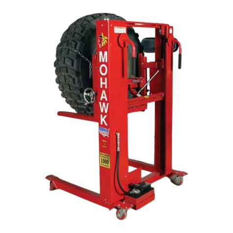
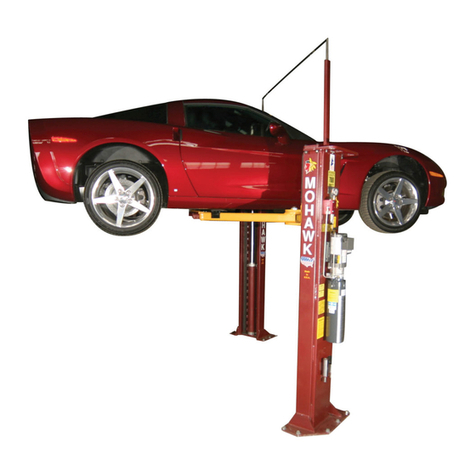
Mohawk MP-18-24VDC Series User manual

1
MOHAWK
INSTALLATION & OPERATION MANUAL
MP-18-24VDC-SERIES
ELECTRIC/HYDRAULIC
PORTABLE LIFT
2, 4, 6 & 8 POST ARRANGEMENTS
MOHAWK RESOURCES LTD.
65 VROOMAN AVENUE
P. O. BOX 110
AMSTERDAM, NY 12010
TOLL FREE: 1-800-833-2006
FAX: 1-518-842-1289
LOCAL: 1-518-842-1431
Mohawk File: MP-18-24VDC
Series 1-30-2018.doc
Rev: 1/30/2018
Part No.: 601-800-373
READ MANUAL THOROUGHLY BEFORE
INSTALLING,
OPERATING OR SERVICING THIS LIFT!!
Deliver these instructions to lift
owner/user/employer along with other
instructional materials furnished with this lift.
Property of American Airlines

IMPORTANT SAFETY INSTRUCTIONS
When using this garage equipment, basic safety precautions should always be followed,
including the following:
1. Read all instructions.
2. Inspect lift daily. Do not operate if it malfunctions or problems have been encountered.
3. Never attempt to overload the lift. The manufacturer’s rated capacity is shown on the
identification label on the power side column. Do not override the operating controls or the
warranty will be void.
4. Only trained and authorized personnel should operate the lift. Do not allow customers or
bystanders to operate the lift or be in the lift area.
5. Position the lift support forks to contact the vehicle tires. Raise the lift until the forks contact
the tires. Check forks for secure contact with the vehicle tires, then raise the lift to the desired
working height.
6. NOTE: Always use all 4 posts to raise and support vehicle.
7. Note that the removal or installation of some vehicle parts may cause a critical load shift in the
center of gravity and may cause the vehicle to become unstable. Refer to the vehicle
manufacturer’s service manual for recommended procedures.
8. Always keep the lift area free of obstructions and debris. Grease and oil spills should always be
cleaned up immediately.
9. Never raise vehicle with passengers inside.
10. Before lowering check area for any obstructions.
11. Before driving vehicle between the posts, position the lift forks to allow vehicle to freely enter
lifting area. To not hit or run over forks as this could damage the lift and/or the vehicle.
12. Before removing the vehicle from the lift area, position the lift forks to allow vehicle to freely
leave lifting area. To not hit or run over forks as this could damage the lift and/or the vehicle.
13. Care must be taken as burns can occur from touching hot parts.
14. Do not operate equipment with a damaged cord or if the equipment has been dropped or
damaged – until a qualified serviceman has examined it.
15. Do not let cords hang over tables, benches or counters or come in contact with hot manifolds or
moving fan blades.
16. If an extension cord is necessary, a cord with a current rating equal to or more than that of the
equipment should be used. Cords rated for less current than the equipment may overheat. Care
should be taken to arrange the cord so that it will not be tripped over or pulled.
17. Always unplug the equipment from electrical outlet when not in use. Never use the cord to pull
the plug from the outlet. Grasp plug and pull to disconnect.
18. Let equipment cool completely before pulling away. Loop cord loosely around equipment
when storing.
19. To reduce the risk of fire, do not operate equipment in the vicinity of open containers of
flammable liquids (gasoline).
20. Adequate ventilation should be provided when working on operating internal combustion
engines.
21. Keep hair, loose clothing, fingers, and all parts of body way from moving parts.
22. To reduce the risk of electrical shock, do not use on wet surfaces or expose to rain.
23. Use only as described in this manual. Use only manufacturer’s recommended attachments.
24. ALWAYS WEAR SAFETY GLASSES. Everyday eyeglasses have only impact resistant
lenses, and they are NOT safety glasses.
SAVE THESE INSTRUCTIONS
Property of American Airlines

iii
MP-18 24VDC- Series Model Name Matrix:
Mohawk Number Total Lift ----------------- Fork Lengths -------------------
Model Name of Posts: Capacity (lbs): Post 1&2 Post 3&4 Post 5&6 Post 7&8
MP-18-505 2 36,000 15"
N/A N/A N/A
MP-18-509 2 32,000 22"
N/A N/A N/A
MP-18-513 2 32,000 22"W
N/A N/A N/A
MP-18-506 4 72,000 15" 15"
N/A N/A
MP-18-518 4 68,000 15" 22"
N/A N/A
MP-18-530 4 68,000 15" 22"W
N/A N/A
MP-18-510 4 64,000 22" 22"
N/A N/A
MP-18-514 4 64,000 22"W 22"W
N/A N/A
MP-18-507 6 108,000 15" 15" 15"
N/A
MP-18-524 6 104,000 15" 15" 22"
N/A
MP-18-558 6 104,000 15" 15" 22"W
N/A
MP-18-525 6 100,000 15" 22" 22"
N/A
MP-18-559 6 100,000 15" 22"W 22"W
N/A
MP-18-511 6 96,000 22" 22" 22"
N/A
MP-18-515 6 96,000 22"W 22"W 22"W
N/A
MP-18-508 8 144,000 15" 15" 15" 15"
MP-18-526 8 140,000 15" 15" 15" 22"
MP-18-560 8 140,000 15" 15" 15" 22"W
MP-18-527 8 136,000 15" 15" 22" 22"
MP-18-561 8 136,000 15" 15" 22"W 22"W
MP-18-528 8 132,000 15" 22" 22" 22"
MP-18-562 8 132,000 15" 22"W 22"W 22"W
MP-18-512 8 128,000 22" 22" 22" 22"
MP-18-516 8 128,000 22"W 22"W 22"W 22"W
Notes:
All Posts with 15" Forks are Rated 18,000 lbs each.
All Posts with 22" Forks are Rated 16,000 lbs each.
W - Denotes Wider Fork Lifts
Property of American Airlines

iv
The Automotive Lift Institute (ALI) is a trade association comprised of US and Canadian
manufacturers and certain national distributors of automotive lifts. For almost 50 years, the ALI
in cooperation with the American National Standards Institute (ANSI) has continued to sponsor
the national standard ANSI/ALI ALCTV:2011 "Safety Requirements for Construction, Testing,
and Validation for Automotive Lifts.”
The new "ALI/ETL Automotive Lift Certification Program" is based on ALI developed methods
and criteria for third party testing of automotive lifts to validate conformance with ANSI/ALI
ALCTV:2011.
For automotive lifts to be certified, manufacturers must execute an agreement with the ALI and
ETL / Intertek Testing Services and must meet certain requirements:
Must be structurally tested in accordance with the test requirements as outlined in ANSI/ALI
ALCTV:2011.
All motor operated units must be listed by a nationally recognized testing laboratory (NRTL)
in accordance with ANSI/UL-201.
The manufacturer's production facility must meet quality control requirements as set forth in
the ANSI Z34.1-1987 and the ALI/ETL Automotive Lift Certification Program Procedural
Guide.
All manufacturer-provided instructions, manuals, and operator safety documents, must meet
the requirements of the ANSI/ALI ALCTV:2011 and ANSI/UL-201.
Lifts meeting these rigid requirements may be listed in the directory of certified lifts and be
labeled with the "ALI/ETL certification mark" (Above on right), and, if applicable, the ETL
listing mark to ANSI/UL-201.
Mohawk has been a long-standing member of ALI and most of Mohawk’s popular models are
currently listed and certified. Other Mohawk models are in various stages of testing. To obtain a
complete and current certification listing, contact Mohawk Resources Ltd. or visit
www.mohawklifts.com or www.ali-directory.org To obtain a copy of the current automotive
lift standard, contact ALI or ANSI or visit www.autolift.org
Some people purchase quality products and others do not. You are assured of quality when you
p
urchase a Mohawk product in compliance with the certification program.
Property of American Airlines

v
HAVE A QUESTION?
Call your local
Mohawk distributor
For parts, service and technical support.
Distributor Place Card Here
Please have this unit’s model and serial number when calling for service.
Model Number ______________________
Serial Number ______________________
OR CONTACT:
MOHAWK RESOURCES LTD.
65 Vrooman Ave.
P.O. Box 110
Amsterdam, NY 12010
Toll Free: 1-800-833-2006
Local: 1-518-842-1431
Fax: 1-518-842-1289
Internet: www.MOHAWKLIFTS.com
E-Mail: Service@MOHAWKLIFTS.com
Property of American Airlines

vi
MOHAWK WARRANTIES
EFFECTIVE DATE: 12/1/2015*
READ THIS WARRANTY IN ITS ENTIRETY
GENERAL WARRANTY INFORMATION:
MOHAWK’S OBLIGATION UNDER THIS WARRANTY IS LIMITED TO REPAIRING OR REPLACING ANY PART OR PARTS
RETURNED TO THIS FACTORY, TRANSPORTATION CHARGES PREPAID BY CUSTOMER WITH AUTHORIZED RETURN (RGA),
WHICH PROVE UPON INSPECTION TO BE DEFECTIVE AND WHICH HAVE NOT BEEN MISUSED. DAMAGE OR FAILURE TO ANY
PART DUE TO FREIGHT DAMAGE OR LACK OF REQUIRED REGULAR DOCUMENTED MAINTENANCE IS NOT COVERED UNDER
THIS WARRANTY. ALL WARRANTY CLAIMS MUST BE PERFORMED IN ACCORDANCE TO MOHAWK’S WARRANTY PARTS
RETURN POLICY (CONTACT MOHAWK’S SERVICE DEPARTMENT FOR MORE INFORMATION).
THIS WARRANTY DOES NOT COVER MIS-DIAGNOSING OF UNIT OR PARTS RETURNED THAT ARE NON-DEFECTIVE. THIS
WARRANTY DOES NOT COVER ANY CONSEQUENTIAL OR INCIDENTAL DAMAGES INCLUDING, BUT NOT LIMITED TO, LOST
REVENUES OR BUSINESS HARM. THIS EQUIPMENT HAS BEEN DESIGNED FOR USE IN NORMAL VEHICLE MAINTENANCE
APPLICATIONS. A SPECIFIC INDIVIDUAL WARRANTY MUST BE ISSUED FOR UNITS THAT DEVIATE FROM INTENDED USAGE,
SUCH AS HIGH CYCLE USAGE IN INDUSTRIAL APPLICATIONS, OR USAGE IN EXTREMELY ABUSIVE ENVIRONMENTS.
MOHAWK RESERVES THE RIGHT TO DECLINE RESPONSIBILITY WHEN REPAIRS OR MODIFICATIONS HAVE BEEN MADE OR
ATTEMPTED BY OTHERS WITHOUT WRITTEN AUTHORIZATION FROM MOHAWK RESOURCES LTD.. THIS WARRANTY DOES
NOT COVER LABOR OR TRANSPORTATION. THIS WARRANTY DOES NOT COVER DOWNTIME EXPENSES INCURRED WHEN
UNIT IS IN REPAIR. THE LIFT MUST BE REGISTERED WITHIN 30 DAYS OF INSTALLATION BY MAILING SUPPLIED
WARRANTY REGISTRATION CARD TO MOHAWK AND MUST BE SIGNED BY A LICENSED ELECTRICIAN. THE MODEL
NUMBER AND SERIAL NUMBER OF THE EQUIPMENT MUST BE FURNISHED WITH ALL WARRANTY CLAIMS. THIS WARRANTY
STATEMENT CONTAINS THE ENTIRE AGREEMENT BETWEEN MOHAWK RESOURCES LTD. AND THE PURCHASER UNLESS
OTHERWISE SPECIFICALLY EXPRESSED IN WRITING. THIS NON-TRANSFERABLE WARRANTY APPLIES TO THE ORIGINAL
PURCHASER ONLY.
THIS WARRANTY DOES NOT COVER NORMAL SURFACE WEAR ITEMS, ITEMS SUBJECT TO ABRASION, OR ITEMS USED IN A
CORROSIVE ENVIRONMENT. SOME ITEMS ON LIFT ARE SUBJECT TO NORMAL “WEAR AND TEAR” AND ARE NOT COVERED
UNDER THIS WARRANTY.
STRUCTURAL AND MECHANICAL COMPONENTS (ALL LIFTS):
STRUCTURAL AND MECHANICAL COMPONENTS OF THIS UNIT ARE GUARANTEED FOR THE BELOW STATED TIME FRAME,
SPECIFIC TO MODEL LISTED, FROM THE DATE OF SHIPMENT FROM FACTORY, AGAINST DEFECTS IN WORKMANSHIP
AND/OR MATERIALS WHEN LIFT IS INSTALLED AND USED ACCORDING TO SPECIFICATIONS.
25-YEARS STRUCTURAL / 10 YEARS MECHANICAL: TWO-POST MODELS A-7, SYSTEM IA-10, LC-12, LMF-12, TP-
16, TP-18, TP-20, TP-26, TP-30. STRUCTURAL ITEMS COVERED INCLUDE LEG, CARRIAGE, SWING ARM AND
SLIDER WELDMENTS (EXCLUDING NORMAL WEAR AREAS AS STATED ABOVE). MECHANICAL ITEMS COVERED
INCLUDE ROLLER BEARINGS AND LIFTING CHAIN.
5-YEAR: MODELS TL-7.
3-YEAR: MODELS TR-19, TR-25, FL-25, TR-30, TR-33, TR-35, TR-50, TR-75, TR-110, TR-120, MP-SERIES LIFTS.
2-YEAR: MODELS PARALLELOGRAM SERIES LIFTS.
1-YEAR: MODELS TD-1000, TD-2000, CT-1000, USL-6000.
POWER UNIT (ALL LIFTS):
ALL POWER UNIT COMPONENTS (MOTOR, PUMP AND RESERVOIR) ARE GUARANTEED FOR TWO YEARS FOR PARTS,
FROM THE DATE OF SHIPMENT FROM FACTORY, AGAINST DEFECTS IN WORKMANSHIP AND/OR MATERIALS WHEN THE
LIFT IS INSTALLED, WIRED BY A LICENSED ELECTRICIAN AND USED ACCORDING TO SPECIFICATIONS.
ELECTRICAL COMPONENTS (ALL LIFTS):
ALL ELECTRICAL COMPONENTS (EXCLUDING MOTOR) ARE GUARANTEED FOR ONE YEAR FOR PARTS, FROM THE DATE
OF SHIPMENT FROM FACTORY, AGAINST DEFECTS IN WORKMANSHIP AND/OR MATERIALS WHEN THE LIFT IS
INSTALLED AND USED ACCORDING TO SPECIFICATIONS. SEE WARRANTY EXCEPTIONS SECTION FOR BATTERIES.
PNEUMATIC-AIR COMPONENTS (ALL LIFTS):
ALL PNEUMATIC (AIR) COMPONENTS (I.E. AIR CYLINDERS AND POPPET AIR VALVES) ARE GUARANTEED FOR ONE YEAR
FOR PARTS, FROM THE DATE OF SHIPMENT FROM FACTORY, AGAINST DEFECTS IN WORKMANSHIP AND/OR
MATERIALS WHEN THE LIFT IS INSTALLED AND USED ACCORDING TO SPECIFICATIONS. COMPONENTS IN A PNEUMATIC
SYSTEM THAT ARE NOT PROPERLY REGULATED, LUBRICATED AND CONDITIONED WITH AN AIR DRYING SYSTEM ARE
NOT COVERED UNDER WARRANTY.
HYDRAULIC COMPONENTS (ALL LIFTS):
EXCLUDING CYLINDERS AND PUMPS (COVERED IN OTHER SECTIONS), ALL HYDRAULIC COMPONENTS (I.E. VALVES AND
FITTINGS) ARE GUARANTEED FOR ONE YEAR FOR PARTS, FROM THE DATE OF SHIPMENT FROM FACTORY, AGAINST
DEFECTS IN WORKMANSHIP AND/OR MATERIALS WHEN THE LIFT IS INSTALLED AND USED ACCORDING TO
SPECIFICATIONS.
Property of American Airlines
vii
HYDRAULIC CYLINDERS (MODEL SPECIFIC LIFTS):
THE FOLLOWING MODELS ARE GUARANTEED FOR 5 YEARS (PARTS ONLY), FROM DATE OF SHIPMENT FROM FACTORY,
FOR HYDRAULIC CYLINDERS, AGAINST DEFECTS IN WORKMANSHIP AND/OR MATERIALS WHEN THE LIFT IS INSTALLED
AND USED ACCORDING TO SPECIFICATIONS: TWO-POST MODELS A-7, SYSTEM IA-10, LC-12, LMF-12, TP-16, TP-18, TP-20,
TP-26, TP-30.
ALL OTHER MODELS ARE GUARANTEED FOR TWO YEARS (PARTS ONLY), FROM THE DATE OF SHIPMENT FROM
FACTORY, FOR HYDRAULIC CYLINDERS, AGAINST DEFECTS IN WORKMANSHIP AND/OR MATERIALS WHEN THE LIFT IS
INSTALLED AND USED ACCORDING TO SPECIFICATIONS (EXCLUDING USL-6000, WHICH IS ONE YEAR).
THE “EXTENDED LIFETIME CYLINDER SEAL WARRANTY” (BELOW) IS APPLICABLE TO THE FOLLOWING MOHAWK LIFTS
ONLY: TWO-POST MODELS A-7, SYSTEM IA-10, LC-12, LMF-12, TP-16, TP-18, TP-20, TP-26, TP-30. SEE MOHAWK’S
“EXTENDED LIFETIME CYLINDER SEAL WARRANTY” FOR SPECIFIC WARRANTY PROVISIONS FOR HYDRAULIC
CYLINDERS.
THE “EXTENDED LIFETIME CYLINDER SEAL WARRANTY” IS AS FOLLOWS:
AS THE ORIGINAL PURCHASER OF A MOHAWK LIFT MANUFACTURED BY MOHAWK RESOURCES, LTD. YOU ARE
ENTITLED TO AN EXTENDED CYLINDER SEAL WARRANTY.
MOHAWK’S OBLIGATION UNDER THIS WARRANTY IS LIMITED TO SUPPLYING MODEL SPECIFIC CYLINDER SEALS. THE
CUSTOMER IS RESPONSIBLE FOR SHIPPING AND HANDLING OF THE SEALS. MOHAWK IS NOT RESPONSIBLE/LIABLE
FOR THE REBUILD OF CYLINDERS BY OTHERS. THIS WARRANTY IS NON-TRANSFERABLE AND RUNS TO THE ORIGINAL
PURCHASER ONLY.
STANDARD OPTIONS (ALL LIFTS):
ALL STANDARD OPTIONS OF THIS UNIT ARE GUARANTEED FOR ONE YEAR FOR PARTS, FROM THE DATE OF SHIPMENT
FROM FACTORY, AGAINST DEFECTS IN WORKMANSHIP AND/OR MATERIALS WHEN LIFT IS INSTALLED AND USED
ACCORDING TO SPECIFICATIONS.
CUSTOM LIFTS AND CUSTOM OPTIONS:
ALL “CUSTOM” LIFTS AND/OR “CUSTOM” OPTIONS ARE GUARANTEED FOR ONE YEAR FOR PARTS, FROM THE DATE OF
SHIPMENT FROM FACTORY, AGAINST DEFECTS IN WORKMANSHIP AND/OR MATERIALS WHEN LIFT IS INSTALLED AND
USED ACCORDING TO SPECIFICATIONS.
WARRANTY EXCEPTIONS (ALL LIFTS):
ADJUSTMENTS: THIS WARRANTY DOES NOT COVER CASUAL AND ROUTINE ADJUSTMENTS SUCH AS, BUT NOT LIMITED
TO: FITTINGS, SENSORS AND SWITCHES, ANCHOR BOLT RE-TIGHTENING, OR ANY SHIMMING OR ADJUSTMENTS
REQUIRED DURING A PROPER AND PROFESSIONAL INSTALLATION BY A QUALIFIED INSTALLER.
MAINTENANCE AND INSPECTIONS: IF THIS UNIT IS NOT MAINTAINED AND INSPECTED IN ACCORDANCE TO THE
RELEVANT SECTIONS IN THE USERS MANUAL FOR THIS SPECIFIC MODEL, WARRANTY IS VOID. OSHA, ANSI AND
MOHAWK REQUIRE THAT RECORDS MUST BE MAINTAINED TO PROVE THAT INSPECTIONS AND MAINTENANCE OF THIS
UNIT HAVE BEEN ROUTINELY PERFORMED BY QUALIFIED INDIVIDUALS.
ABUSE: IF THIS UNIT IS FOUND TO BE OVERLOADED (PURPOSELY OR UNKNOWINGLY), USED IN A SITUATION BEYOND
ITS INTENDED FUNCTION, NOT MAINTAINED & INSPECTED REGULARLY, USED IN AN ABUSIVE ENVIRONMENT OR
BEYOND NORMAL SHOP USAGE, THIS WARRANTY IS VOID IN ITS ENTIRETY.
NON-EXISTENT PROBLEMS: FOR SERVICE VISITS, PART REPLACEMENTS, LABOR, ETC. FOR PARTS FOUND TO BE NON-
DEFECTIVE, OR FOR A UNIT DIS-FUNCTION THAT DOES NOT EXIST, IT IS THE LIFT OWNER THAT REQUESTED THE
SERVICE VISIT WHO BEARS THE RESPONSIBILITY OF ALL RELATED EXPENSES.
BATTERIES: ALL BATTERIES CARRY THE BATTERY MANUFACTURER’S WARRANTY. MAINTENANCE REQUIREMENTS AND
ABUSE PROVISIONS ARE AS STATED BY THE BATTERY MANUFACTURER. REFER TO BATTERY MANUFACTURER’S
WARRANTY.
SPECIAL/MODIFIED INSTALLATIONS: THIS WARRANTY DOES NOT COVER “NON-TRADITIONAL” INSTALLATIONS.
INSTALLATIONS ARE TO BE DONE ACCORDING TO SPECIFICATIONS, OR THE WARRANTY IS VOID.
WEARABLE COMPONENTS: SOME ITEMS ON LIFTS ARE SUBJECT TO NORMAL “WEAR AND TEAR” AND ARE NOT
COVERED UNDER THIS WARRANTY.
NON-VEHICLE / RE-PURPOSED LIFTS: THIS WARRANTY DOES NOT COVER LIFTS THAT ARE “RE-PURPOSED” TO RAISE
AND LOWER EQUIPMENT THAT ARE NOT CONSIDERED VEHICLES.
* THIS WARRANTY SUPERSEDES ALL OTHER WARRANTY POLICIES PREVIOUSLY STATED AND IN ALL OTHER MOHAWK
PRODUCT SPECIFIC LITERATURE (MANUALS, BROCHURES, ETC.).
Rev 12/1/2015
Property of American Airlines

viii
CONTENTS
TEXT
PAGE
GENERAL NOTES & WARNINGS 1
LIFT LIMITATIONS 2
POWER SUPPLY REQUIRMENTS 3
OPTIONAL EQUIPMENT 4
LIFT SPECIFICATIONS (15” FORK MODEL) 5
LIFT SPECIFICATIONS (22” FORK MODEL) 6
DESIGN & CONSTRUCTION FEATURES 7
MOBILE LIFT SET-UP 8-9
MOBILE LIFT OPERATION 10-11
FINAL CHECKOUT 12
SAFETY TIPS 13
MAINTENANCE INSTRUCTIONS 14
EXPLANATION OF COMPUTER SYSTEM 15-22
TROUBLE SHOOTING 23-24
MAINTENANCE & SERVICE CHART 25
PARTS
DWGNO.
POST ASSEMBLY (15” FORKS) MP-5400-A-001
POST ASSEMBLY (22” FORKS) MP-5400-A-004
JACK ASSEMBLY MP-0400-A-007
POWER UNIT ASSEMBLY MP-5400-A-003
FLOOR ROLLER ASSEMBLY MP-0500-A-001
LOCK ASSEMBLY MP-5200-A-001
CARRIAGE ASSEMBLY MP-0700-A-001
CYLINDER ASSEMBLY MP-0900-A-001
CONTROL BOX ASSEMBLY MP-5100-A-001
CONTROL BOX SUB-ASSEMBLY MP-5100-A-003
CONTROL PANEL ASSEMBLY MP-5100-A-004
TERMINAL STRIP #1 ASSEMBLY MP-5100-A-020
TERMINAL STRIP #2 ASSEMBLY MP-5100-A-021
CHARGER ASSEMBLY MP-5100-A-012
STRING POT ASSEMBLY MP-5100-A-014
BATTERY BOX ASSEMBLY MP-5300-A-001
PENDANT ASSEMBLY (OPTIONAL) MP-1300-A-020
ILLUSTRATIONS
CHARGER STATUS LIGHTS
BATTERY METER LIGHTS
JACK OPERATION
JACK RELIEF SETTING
ENCLOSURE DIAGRAMS
COMMUNICATION CABLE & DUMMY PLUG DIAGRAMS
WARNINGS PICTOGRAM
CAUTIONS PICTOGRAM
SAFETY INSTRUCTIONS PICTOGRAM
SCHEMATICS
DWGNO.
HYDRAULIC SCHEMATIC MP-5000-A-002
ELECTRICAL SCHEMATIC & WIRING DIAGRAMS (3 PAGES) MP-5000-A-001
CHARGER
CHARGER INFORMATION
BATTERY CARE
BATTERY INFORMATION
OPTIONS
ALL INFORMATION, ILLUSTRATIONS, AND SPECIFICATIONS IN THIS MANUAL ARE BASED ON THE LATEST PRODUCT INFORMATION
AVAILABLE AT THE TIME OF PRINTING. WE RESERVE THE RIGHT TO MAKE CHANGES AT ANY TIME WITHOUT NOTICE.
Property of American Airlines
14
MAINTENANCE INSTRUCTIONS
1. The channel sections where the carriage bearings ride against should be cleaned and
lubricated twice a year (once every 6 months) using a light lubricant (WD-40). The
channel sections where the slide blocks ride against should be cleaned and lubricated
twice a year (once every 6 months) using a light lubricant (WD-40).
2. The main carriage bearings are factory lubricated and may require additional periodic
lubrication. When additional lubrication is desired on these, it is recommended to use
CAM2 – Multipurpose #2 Grease (Part No. 86035) or equivalent. Use approximately 2
oz. per bearing.
3. Weekly, or whenever the hoist is used after any extended down time, the power supply
and communication cables should be checked to make sure that there are no nicks or cuts
which may reduce or compromise the insulation. Use a de-greasing cleaner to clean all
cables so they maintain their visibility (Ensure cables are disconnected when cleaning
them and do not spray cleaner on end connections). Also, check visually the hydraulic
line connections for leaks and tighten or repair as necessary.
4. Check your hydraulic fluid annually. Every five years the hydraulic fluid should be
changed using new Dexron III ATF. Drain the reservoir tank only when the carriage is in
the lowered position. Fill with 3.25 US gallons per reservoir.
5. Every three months check snap rings on wheels and carriage lock. Apply a light coating
of lubricant to pins as needed (WD-40).
6. In case of electrical break down have qualified service personnel service the lift using
only factory direct replacement parts.
7. Call your Distributor or Factory direct if you have any questions with regards to
operating the lift or need of replacement parts.
NOTE:
ONLY TRAINED LIFT SERVICE PERSONNEL ARE PERMITTED TO
REPLACE WORN OR BROKEN PARTS.
REPLACE FAULTY PARTS WITH GENUINE MOHAWK
RESOURCES LTD. FACTORY DIRECT PARTS ONLY.
Property of American Airlines
15
EXPLANATION OF COMPUTER SYSTEM
SYSTEM ACTIVATION
All posts on this system are identical (there is no master or slave columns). After the posts are connected as
described in the lift setup, the lift is ready to be activated. As each post is turned on, they “search” for each
other, establishing a shared network for synchronizing and controlling the lift as a system.
The first thing the user must do to operate the lift is to verify that the network is detecting the desired number
of columns to use. Pressing the selection key arrow to the right of “YES” will allow the user to begin raising
and lowering the lift.
Example Screen shows lift with 4 posts present in system, Post
#1, #2, #3, and #4. Pressing the right selection key arrow will
activate lift.
Post presence will be affected by how many posts are
connected in the system, if they are connected properly (see
lift setup), if the dummy plugs are connected properly (see lift
setup), and if they are turned on (to “Operate Lift”).
OPERATION OF SYNCHRONIZED LIFTING OR LOWERING
Each PLC (programmable logic controller) is “addressed” which establishes its identity on the network. For
example, post #1 has a PLC with address #1, etc. Once communication of the network of PLCs is established,
each PLC senses control and position inputs from each other. Be aware that pairs are designated as post #1&2,
post #3&4, post #5&6, and post #7&8, regardless of where they are physically placed in the system.
The height of each carriage above floor level is measured by string potentiometers (see next section) and
compared to the other carriages by the PLC network. During raising, if any one carriage position is more than
1” higher than the lowest carriage, the higher (fastest) one slows down or stops to allow the lowest (slowest)
one to catch up. During lowering, if any one carriage position is more than 1” lower than the highest carriage,
the lower one slows down or stops to allow the highest one to catch up. This is all done by shifting motor
contactors and lowering solenoid valve.
When lifting in Pair or Single mode, counting is not done, resulting in the PLC’s seeing a “synchronized”
state after this adjustment is made. There are limits on how far the lift will allow a Single post to raise/lower,
and how far a Pair of posts can raise/lower relative to the rest of the system.
If you turn off the unit or press the Emergency Stop button, the computer position for each column is still
retained and the columns will still maintain synchronized relative positions.
Property of American Airlines

16
FUNCTION OF STRING POTENTIOMETER (String-Pot)
There is a string potentiometer (string-pot) mounted on the top of each column, and connected to each
carriage, which senses the movement of the carriage. The string-pot sends an absolute analog (4-20mA) signal
to the PLC as the string is pulled in and out of the sensor. This signal is absolute, which means that the lift
will always know the height of the lift, even when powered off and on again. This signal is directly translated
into height position and can be witnessed by viewing the Post Height Screen, F2. If raising or lowering is not
possible, manually pulling the string-pot cable, while the unit is powered and pressing F2, will enable you to
see the height changes.
FUNCTION MENUS
The control screen has 10 function keys that will display various menus. They are as follows:
F1: Post ID and Active Posts Display
This screen will display the Post ID and all the active posts of the
system it is connected to.
i.e. The display to the left shows post #2 connected in a 4-post
system manner with posts #1, 2, 3, & 4.
F2: Post Height Display
This screen will display the current post height in inches.
i.e. The display to the left shows the post at a height of 42 inches.
(Note the tolerance of +/- ½ inch)
Property of American Airlines

17
F3: Weight Display
This screen will display 1 of 3 screens, depending if the lift has the hydraulic pressure sensing option present.
If all the posts in the system have the pressure sense option, the screen (A) will display showing the weight on
the post and the total weight of the system. If only the present column has the pressure sense option, then
screen (B) will display, showing only the post weight. If you are at a column that does not have a pressure
sense option, then screen (C) will display. (Note the tolerance of +/- 3% in weights shown)
Refer to F9 for factory settings enabling and disabling the pressure sense option in each post.
A B C
F4: Voltage Display
This screen will display the current voltage (VDC) of the battery
system.
i.e. The display to the left shows the post at 23.05 VDC.
(Note the tolerance of +/- 0.5 VDC)
Property of American Airlines

18
F5: User Settings Display
This screen displays general user settings of the lift. Pressing enter and the up or down arrow keys will scroll
through this menu. Press Escape and the Exit Key to Exit Menu. Item shown in this menu are as follows:
Post ID
Post Capacity
Serial Number
Maximum Height Limit
Warranty Expiration Date
Lifting Cycles Used
F7: Maintenance/Service Display
(Distributor or Factory Password Protected)
This screen displays general service and inspection information and
service contact information. Distributor or Maintenance personell
password required. (See F10).
F8: Configuration Settings (Factory Password Protected)
This screen displays configuration settings for the battery voltage
monitoring, string-pot height sensor, and the pressure sensor. This
is only accessible with the factory password (See F10).
Property of American Airlines

19
F9: Factory Settings (Factory Password Protected)
This screen displays factory settings. This is only accessible with
the factory password (See F10).
F10: Password
This screen allows entry of the password which will give access to
the PLC configuration settings and screens F9 and F10. Enter either
the Distributor Password to give limited access to F7 screen, or the
Factory Password to give access to all password protected screens.
ERROR MESSAGES:
The following are a list of error messages that may display if certain situations arise.
Post Count Error:
This screen appears if the user says “NO” to the initial Active Posts
response screen.
(See System Activation above)
Property of American Airlines

20
Comms Lost Error:
This screen appears if any column in the system is lost after it was
previously present. This could be due to a column being turned off
or if the communications to the post are not connected. The post in
which communications is lost will be identified on the screen. All
controls will be locked-out until this is remedied.
i.e. The display to the left shows loss of communications to post 3.
E-Stop Error:
If any post in the system has an Emergency Stop button pushed, this
screen will appear showing which post was stopped. All controls
will be locked-out until this is remedied.
i.e. The display to the left shows the emergency stop button pushed
on post 2.
Lift at Max Height Error:
Indicates that a post has raised to the maximum height setting (set
in the factory setting menu). The post that has reached this height
will be identified. Raising and parking are not allowed in this
situation, only lowering. (Note that the max height setting is
adjustable for buildings with low clearance, etc..)
i.e. The display to the left shows that post 4 has reached max
height.
Property of American Airlines

21
Maximum Offset Error:
There are limits on how far any post can be out of level from any other post, even when using Single and Pair
overrides. If any post reaches its limits, one of the following screens will be displayed (depending on if the
unit is being used in All, Pair, or Single). The highest and lowest posts will be identified. Raising is only
allowed on the lowest post, Lowering only allowed on the Highest post. These offsets are normally outside
the bounds of normal usage and prevent extreme out of level conditions.
Lock Not Releasing Error:
This screen will only occur during Lowering of the lift. This screen
indicates that one of the locks is not released, and it will prevent the
lift from lowering. This may be due to a lock on the identified post
from being mechanically parked, the solenoid not pulling the lock
back, or the sensor not “seeing” the lock pulled back (sensor may
need to be adjusted). The post that causes this error will be
identified.
i.e. The display to the left shows that post 1 lock is not released.
Loss of Motion Error:
This screen will occur if any post is not sensing motion when a
raise or lowering command is present. This may occur if a post
string-pot is disconnected, malfunctioning, or cable is broken. This
also may occur if the lift is lowering onto an obstruction to prevent
its motion. Press Exit key at post this occurs at to remove message.
(Note: If message remains, then the string-pot is disconnected and
needs to be repaired)
i.e. The display to the left shows that post 4 experienced a loss of
motion while raising or lowering.
Property of American Airlines

22
Post Overload Error: (Optional)
This screen will appear if any post has a weight on it that exceeds
the capacity of the post. Post capacities are set in the factory setting
menu. Raising and parking are not allowed in this situation, only
lowering. (This error will only be present if the lift has the pressure
sensing option.)
i.e. The display to the left shows that post 3 & 4 are overloaded.
Battery Warning:
This indicates that one of the post’s batteries are low on charge and
need to be recharged. (Also, refer to battery meter above control
screen.) Pressing the “OK” button will allow lift function, but only
for a few cycles until the “Battery Low” error occurs (see below).
i.e. The display to the left warns that post 6 battery is low.
Battery Low Error:
This indicates that one of the post’s batteries is too low on charge
and needs to be recharged. The lift will not function until this post
is fully recharged.
i.e. The display to the left shows that post 6 battery is low and lift
will not function until post 6 is fully recharged.
Property of American Airlines

23
TROUBLE SHOOTING
NOTICE: Read manual prior to trouble shooting. A good understanding of how this lift
and its controls function will greatly help in understanding any problems that may
occur.
START-UP:
Problem: Upon power up, screen does not illuminate (on any single column).
Solution1: Verify that power cables are unplugged from charger inlets on all posts. Post will not power up
unless power is removed from charger.
Solution2: Check to see that battery cables are connected to batteries properly. Also verify 24 VDC at the
control panel.
Solution3: PLC may have faulty screen. Consult Mohawk Service department.
Problem: All posts are not shown on activation screen.
Solution1: Verify that all posts in system are turned on to “Operate Lift”.
Solution2: Check for proper communication cable and dummy plug connection of all posts. (See lift setup)
Solution3: Possible faulty communication cable or dummy plug. Consult Mohawk Service department.
Problem: Error Code present.
Solution: See Error Code Section in this manual.
DURING OPERATION:
Problem: Error Code present.
Solution: See Error Code Section in this manual.
Problem: There is more than 1-1/2” height difference between carriages.
Solution: This may be due to the fact that one column was operated on SINGLE before operating the unit in
the ALL mode. This may also be due to operating in the PAIR mode before operating in ALL mode.
Problem: Lift jack not raising lift or lift jack not collapsing when loaded.
Solution1: Lift jack relief valve needs to be adjusted. Turn relief set screw clockwise to increase lifting
ability of jack. Turn relief set screw counter-clockwise to reduce lifting ability of jack. See illustration in
back of manual.
Property of American Airlines

24
Solution2: Jack is low on oil. Add oil. (Dexron III AFT or equivalent)
Problem: Carriage is lowering on its own.
Solution1: Check that there are no oil leaks by checking around the column. If so, repair the leak condition.
Solution2: If Solution 1 does no produce results, check for leakage of cylinder piston seals. Remove black
plastic vent tube from power unit reservoir tank port and see if any fluid is flowing out. If so, cylinder piston
seals are leaking. Contact Mohawk’s Service department.
Solution3: If Solution 2 does not produce results, the lowering valve(s), located on the power unit may have
collected some dirt, preventing them from sealing properly. Make sure that the carriage is lowered to floor
level in order that there is no pressure in the system. Disconnect the power so that no one can start the unit.
You can now remove the lowering valve(s). Disconnect the electrical leads from the solenoid using a
screwdriver to remove the screw holding the two mating connectors. Remove the lowering valve(s) from the
power unit and check to see that there is no foreign material in the valve ends, which prevent the balls from
sealing. Remove the foreign material. If you cannot find any problem, replacement of valve may be
required. Contact Mohawk’s Service department.
Solution4: If Solution 3 does not produce results, the power unit’s main load holding check valve may have
collected some dirt, preventing it from sealing properly. Make sure that the carriage is lowered to floor level
in order that there is no pressure in the system. Disconnect the power so that no one can start the unit. You
can now remove the check valve components and check to see if there is any foreign material in the valve
cavity to prevent the ball from sealing. Remove the foreign material. If you cannot find any problem, re-
seating of the valve, or replacement of valve may be required. Contact Mohawk’s Service department.
Property of American Airlines

25
MODEL:
SERIAL NUMBER:
DATE OF INSTALLATION:
SERVICE CHART
DATE PART REPLACED / SERVICED SERVICE
COMPANY SERVICED BY
MAINTENANCE CHART
DATE MAINTENANCE PERFORMED SERVICE
COMPANY SERVICED BY
Property of American Airlines
This manual suits for next models
24
Other Mohawk Lifting System manuals

Mohawk
Mohawk TR-33 User manual

Mohawk
Mohawk IA User manual

Mohawk
Mohawk LMF-12 User manual

Mohawk
Mohawk ML-220 User manual

Mohawk
Mohawk TR-25A User manual

Mohawk
Mohawk USL-600 Guide

Mohawk
Mohawk TP-18 User manual

Mohawk
Mohawk TR-110 User manual

Mohawk
Mohawk V-085-C-X User manual

Mohawk
Mohawk TD-1000-AH User manual