molex 57225-7100 User manual

INSTRUCTION MANUAL
IS-0096E
ISSUED
1997-04-11
REVISED
2007-02-23
REV.
C
AIR PRESSURE TYPE
DESKTOP
TERMINATOR
(Machine Number: 57225-7100)
OPERATING MANUAL
Molex Japan Co., Ltd.

Molex Japan Co., Ltd.
Contents of Update
Instruction Manual No.
IS-0096E
Title
AIR PRESSURE TYPE DESKTOP TERMINATOR
Machine Number
57225-7100
Rev.
Issued
Description
0
1997/04/11
New creation release.
ECN-JT70044
A
2002/09/30
Added Safety Precautions, Quality Precautions, and Startup Checklist.
ECN-JM30004
B
2006/06/09
Changed to the same content as a bilingual version.
ECN-JM60025
C
2007/02/23
Changed the form.
ECN-JT2007-0076
Prepared by
Y. Ishiwata
Checked by
T. Yoshida
Approved by
A. Horino

Table of Contents
<Safety Precautions> Page
1. Introduction ...................................................................................................A-1
2. To operation supervisors.............................................................................A-1
3. Dangerous operations..................................................................................A-1
4. Careful handling............................................................................................A-2
5. Installation site..............................................................................................A-2
<Quality Precautions>
1. Introduction ...................................................................................................B-1
2. Must be carried out.......................................................................................B-1
3. Must not be carried out ................................................................................B-1
1. Description 1
2. Machine Configuration and Applicable Products
2.1. Machine Name and Configuration................................................................................... 1
2.2.Applicable Connector and Wire....................................................................................... 1
2.3. Machine Appearance and Unit Name.............................................................................. 2
3. Specifications
3.1. Machine Specifications.................................................................................................... 3
3.2. Power Source Specifications........................................................................................... 3
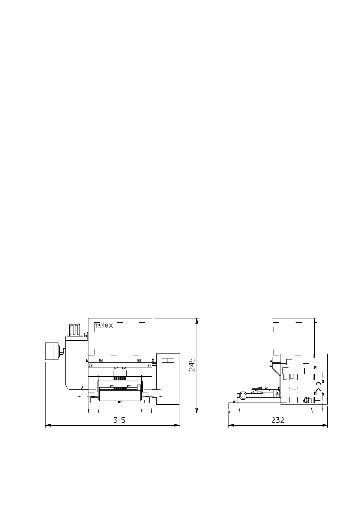
3.3. External Size and Weight ................................................................................................ 3
3.4. Operating Environment Conditions ................................................................................. 4
3.5. Installation Space............................................................................................................. 4
4. Installation of Machine
4.1. Installation........................................................................................................................ 5
4.2. Operation Preparation ..................................................................................................... 5
5. Operation Method
5.1. Termination Procedure..................................................................................................... 6
5.2. Set of Connector.............................................................................................................. 7
5.3. Wire Arrangement and Termination................................................................................. 8
6. Maintenance and Check
6.1. Daily Maintenance........................................................................................................... 9
6.2. Checking of Machine..................................................................................................... 10
6.3.Adjusting Method of Termination Depth..........................................................................11
6.4.Adjusting Method of Connector Position ....................................................................... 12
7. Cause and Measures of Breakdown...................................................................................... 13
8. Block Diagram14
9. Parts List
9.1. Termination Unit............................................................................................................. 15
9.2. Press Unit ...................................................................................................................... 17
10. Startup Checklist..................................................................................................................... 19

A–1
<Safety Precautions>
Please read the following before operating the machine.
1. Introduction
Thank you for choosing our AIR PRESSURE TYPE DESKTOP TERMINATOR.
This instruction manual is prepared so that the machine is properly used.
Please take the time to read this manual, making sure you understand the operating
procedures described herein before attempting to operate the machine.
2. To operation supervisors
1) Operators should fully understand the contents of this manual before operation.
2) If operators do not understand English, translate this manual into the proper language.
3) Keep this manual near the machine so that operators can refer to it anytime.
3. Dangerous operations
Observe the following precautions to prevent a life-threatening accident.
1) Don’t insert a part of your body or other foreign materials into the machine when it is running.
2) Don’t place the machine on an unstable, off-balanced worktable from which the machine might
fall down.
3) If more than two operators are engaged in operation or checkup at the same time, even slight
miscommunication might lead to a serious accident.
4) Don’t put your face too near the operation area, as flying fragments may hurt you seriously.
Caution
1) Unauthorized reproduction of this document in part or in whole is prohibited.
2) The contents of this document are subject to change without notice.
3) Molex Japan Co., Ltd. assumes no responsibility for losses resulting from use or
misuse of this document.

A–2
<Safety Precautions>
Please read the following before operating the machine.
4. Careful handling
Keep the items below to use the machine safely and properly.
* Please contact our application-tooling group if something’s wrong with the machine.
1) Replacement and checkup of the parts
When you have to put your hands inside the machine to replace or check the parts, confirm in
advance that unplugging the power cable and shutting off the air supply.
2) Don’t touch the internal electric circuit
Don’t remove the safe cover of this machine during operation.
The electric circuit is included in this place, and it is not only dangerous, but it will become the
cause of failure if a hand is touched.
3) Malfunctions
If you notice any unusual sound or movement in the machine, stop the operation immediately
and check the suspicious parts.
4) Foreign materials
If foreign materials such as water or metals accidentally get inside the machine, stop the
operation immediately and remove those materials.
5. Installation site
Be careful about the following items when you install the machine.
1) Temperature and humidity
Don’t operate the machine in extremely high/low temperature or extremely high humidity.
* Place it where the temperature is stable around 23 degrees centigrade and the air is well
ventilated.
2) Dust and corrosive gas
It will become the cause of failure if dust, corrosive gas, etc. are in the circumference of this
machine.
* Please don’t install this machine to such a place.
3) Near electromagnetic sources
If the machine is used near a surge generator or powerful electromagnetic source, there is a
possibility of carrying out incorrect operation.
* Please don’t operate this machine in such a place.
4) In place where unstable power sources
The machine may incorrect-operate in the place where change of power supply voltage is
sharp beyond a specification value.
* Please don’t install this machine in such environments.

B–1
<Quality Precautions>
You surely carry out the following for defect-free production.
1. Introduction
In order not to produce a defective article with this machine, this chapter has described “Must
be carried out”, and “Must not be carried out”as an important matter on operation.
Keep in mind that there is a possibility that a defective article will be produced when
not protecting this.
2. Must be carried out
Please be sure to perform the following matter to maintain product quality.
1) Enforcement of startup check
Please check the machine in accordance with the “startup checklist” described in this
document before an operation start, and start operation after confirming nothing is wrong with
the machine.
* If the check is neglected, there is a possibility that a defective article will be produced.
2) Confirmation of quality
Please start the production after confirming the quality of a product picked up from the first
operation, and it passes all of the claims required in the ITD (termination) specifications and
the harness drawing of a corresponding connector.
* It is recommended to initiate the operation on the preferable condition that enough margins
for the standard are identified.
3. Must not be carried out
Please don’t perform the following matter by any means to maintain product quality.
1) Using of Unqualified wire
Please don’t use an unqualified wire. There is a possibility of causing connector breakage and
termination defect by mismatching of a wire outer diameter.
* Please operate using a qualified wire.
2) Too much deeply termination
Don’t terminate a wire too much deeply. It may lead to the breakage of connector and
termination punch.
* Please terminate a wire in the termination depth of a standard value.
3) Wire scrap unexclusion
Because it causes the wire guide (comb) damage when terminating with the cut wire scraps
left for the wire guide, it is a prohibition.
* Please terminate after excluding the wire scraps from the wire guide without fail.

Page 1
1. Description
This machine is an air pressure type desktop terminator that terminates the 15 discrete wires or
less to the 2.0mm pitch Mi2 connector of Molex.
As a feature, the termination work with a high reliabilitry can be done because this machine
equips the detection switch of the slide table in the termination position and the air pressure
shortage detection switch.
In addition, it also has the feature that the wire protruding length is stabilized by which carried
out the termination after cutting the point of the wire.
2. Machine Configuration and Applicable Products
2.1. Machine Name and Configuration
1) Machine name:
AIR PRESSURE TYPE DESKTOP TERMINATOR
2) Machine number:
57225-7100
3) Machine configuration:
(1) Air press main body
(2) Slide table
(3) Foot switch
2.2. Applicable Connector and Wire
1) Connector:
Molex 2.0mm pitch Mi2 connectors
52484-****: Mi2 Receptacle (From 2 to 15 circuits)
2) Wire:
UL1061/UL1571 AWG#26/#28 discrete wire, or other Molex qualified
wires. (Mixture of different wire is impossible)
Insulation outside diameter = From phi 0.85mm to phi 1.05mm
(Conductor composition = 7-twist tin plating copper wire)

Page 2
2.3. Machine Appearance and Unit Name
Air press main body
Slide table
Foot switch

Page 3
3. Specifications
3.1. Machine Specifications
1) Number of termination
possible wires:
15 wires or less
2) Number of termination
possible circuits:
From 2 to 15 circuits
(When two or more connectors are terminated, it is a number of
total circuits in which it assumes between connectors one circuit)
3) Wire arrangement
method:
One wire is arranged in the comb of a prescribed circuit number of
the wire guide, and it fixes to the double-sided adhesion tape on the
table.
4) Termination method:
The termination is executed after cutting the point of the wire
arranged in the wire guide (comb) by the termination punch,
5) Table position detection:
The slide table is detected being pushed into the termination
position with the switch.
6) Start of termination:
The termination starts when turns “ON”the foot switch while turned
“ON”the table position detection switch.
7) Termination source:
Air cylinder
(Phi80mm and stroke of 25mm)
8) Termination force:
Approx. 2500N (At the air pressure of 0.5MPa) (Approx. 250kgf)
9) Adjustment of termination
depth:
The termination depth can be adjusted with a stopper bolt on the
upper side die-set.
10) Air pressure shortage
detection:
The state that the air pressure decreases more than the set lower
bound value is detected.
(Lower bound value is set as 0.4MPa)
11) Controller:
Control method with special circuit.
3.2. Power Source Specifications
1) Power supply:
AC100 V, 50/60 Hz, 1 A or less
2) Air supply:
0.5 MPa (Approx. 5 kgf/sq. cm), Dryness compressed air

Page 4
3.3. External Size and Weight
1) External size:
315 (width) × 232 (depth) × 2450 (height) mm
2) Weight:
Approx. 12kgf
3.4. Operating Environment Conditions
1) Operating ambient temperature:
From 5 to 35 degrees centigrade (Away from direct sunlight)
2) Operating ambient humidity:
From 35% to 85% RH (No condensation)
3) Operating atmosphere:
Atmosphere should be free of corrosive gases and
contaminants such as dust or lint.
4) Voltage variation:
Within +/-10% (of the rated voltage)
3.5. Installation Space
Machine installation space required for the purposes of performing operation and maintenance
checkups.
(On the worktable from 700mm to 750mm height)
900 (width) × 700 (depth) × 2000 (height) mm
Recommended worktable construction: Anti-vibration feature such as adjuster feet (Load
capacity: 200kgf or more)

Page 5
4. Installation of Machine
4.1. Installation
1) An air press is arranged from the edge of a solid worktable to 100mm or more inner side, and the
stable installation without shakiness is checked.
2) A power supply cord is connected to the 2-pole metal connector on the backside of an operation
panel, and a foot switch is connected to the 3-pole metal connector.
3) A power supply cord is connected to the supply source of AC100V.
4) The air supply tube is connected to the air piping mouth of a filter regulator.
4.2. Operation Preparation
1) The power switch of the operation panel is “ON/OFF”, and the switch lamp “light/turn off” is
confirmed.
2) Where the pressure adjustment knob of the pressure gauge of a filter regulator is pulled, a knob
is turned, and air pressure is adjusted to 0.5MPa.
“Note” Please set the air pressure shortage detection switch (red needle) to 0.4MPa with a slotted
screwdriver.
Pressure adjustment knob
(Pull up and turn it)
Pressure gauge
Pressure shortage detection
switch adjustment screw

Page 6
5. Operation Method
5.1. Termination Procedure
Set of connector
Open the wire guide (comb), set a connector on a left standard, and
the wire guide is locked to the table after shutting.
Wire arrangement
Arrange one wire into the comb of the predetermined circuit number
of the wire guide, and fix it to the front double-sided adhesion tape.
Pushing of table
Push in the table to the interior of the machine after ending the
arrangement of all wires.
(The table position detection switch is turned “ON”)
Termination
Turn “ON” the foot switch in the state, and termination is executed.
Drawing out of table
Draw out the table and open the wire guide after eliminating the
wire scraps.
Taking out of connector
Remove the wires from the adhesion tape and take out the
terminated connector.

Page 7
5.2. Set of Connector
1) Pull the “slide table (1)” to the operator side and open the “wire guide (2)”.
2) Loosen the fixed screw of a “right stopper (3)”in the connector set part and slide it rightward.
3) Set a “connector (4)”, force lightly the “right stopper (3)”to the connector, and fix it with a screw.
(This adjustment is carried out only at the time of the circuit number change)
4) Shut the “wire guide (2)”and lock on the slide table with the “hold lever (5).”
“Note”Please do not move the “left stopper” for the set standard of the connector.
Wire guide (2)
Hold lever (5)
Slide table (1)
Connector (4)
Right stopper (3)

Page 8
5.3. Wire Arrangement and Termination
1) Arrange one “wire (1)”in the comb of the predetermined circuit number of the “wire guide (2)”,
and fix it to a “double-sided adhesion tape (4)”in the position to which the “wire point (3)”comes
out a little from the comb edge.
2) After ending the arrangement of all wires, grasp the “knobs (6)”of the “slide table (5)” by both
hands, push it into the interior in the machine completely, and the termination is executed by
turning on the “foot switch” in the state.
3) After termination, draw out the slide table to the front and remove the cut “wire scraps”from the
“wire guide (2)”completely.
4) Open the “wire guide (2)”and take out the terminated connector from the slide table.
“Note”Please remove the “wire scraps”because it causes the wire guide damage and a defective
termination.
Wire (1)
Wire guide (2)
Double-sided adhesion tape (4)
Wire point (3)
Knob (6)
Slide table (5)

Page 9
6. Maintenance and Check
6.1. Daily Maintenance
1) Maintenance of machine
Before a work start, please carry out the machine check in accordance with the “startup
checklist”in this manual, and start work after checking that it satisfies a standard.
* Please record each check result simultaneously.
2) Removal of foreign article
Foreign substances such as dust and wire waste will accumulate on “termination punch”,
“wire guide”, “connector set part”and “table slid part”during operation.
Please remove them from the machine every day after turning off the power and checking
safety.
* Neglect may become the cause that a poor wire cutting and a termination defect.
3) Cleaning of work end
Please wipe with a dry cloth lightly after cleaning a machine with compression air every day at
the time of a work end. There is an effect that maintains a sensor function and prevents
rusting.
4) Lubrication
Apply a proper amount of “Lithium family grease” (JIS No. 2) or equivalent to the die set and
the “U”-shaped ditch of the wire guide side with the frequency of once a month.
5) Discharge water
Please discharge water collected in the filter regulator of the air supply entrance with the
frequency of once a week.

Page 10
6.2. Checking of Machine
Please reconfirm the standard value with Mi2 IDT (termination) specifications of the latest
version before it works.
1) Termination (IDT) depth
The termination depth must meet the standard value.
<Standard> Termination depth = 0.7+0.1/-0.15mm
2) Wire protruding length
The size between the inner wall of a hosing and a wire point must meet the standard.
<Standard> Wire Protruding Length = 0.5mm or less
3) Damage of wire insulation
There must not be remarkable damage of the wire insulation with the termination punch and
the wire guide, etc.
4) Damage of housing
There must not be remarkable damage of the housing with the termination punch.
5) Conductor shear drop
The amount of the conductor shear drop of the cut wire must not be remarkably.
Wire protruding length
Termination depth (center of pieces)
Wire

Page 11
6.3. Adjusting Method of Termination Depth
1) Turn “OFF”the power supply switch of the terminator, and detach the “safety cover on the front.
2) Remove the “stop screw (1)”on the slide base, and detach the “slide table (2)”.
3) Loosen the “nut (4)”at the center of the “upper die-set (3)”, and adjust the termination depth
turning the “stopper bolt (5)”.
4) The direction of the adjustment and the amount of the adjustment are as follows.
* To shallow:
* To deep:
* Adjustment value:
Turn the stopper bolt in the “direction of “A”.
Turn the stopper bolt in the “opposite direction of A”.
Approx. 1.0mm/one turn
5) After adjusted, fasten the “nut (3)”firmly where the wrench is set to the “stopper bolt (4)”.
6) Henceforth, re-set the remaining parts in the reverse order.
“Note”After adjusted it, please start the production after confirming the termination depth meets the
standard by the trial operation.
Nut (4)
Stopper bolt (5)
Upper die set (3)
Slide table (2)
Stop screw (1)

Page 12
6.4. Adjusting Method of Connector Position
1) Open a “wire guide (1)”, loosen the fixed screw of a “left stopper (2)” (it does not usually move
with fixation), and adjust the connector position finely.
2) After adjusted it, confirm that the punch mark on the wire is in the center part of the IDT slot by
the trial operation. The presence of the wire insulation crack is confirmed at the same time.
3) After that, the termination of the different circuit number is carried out only by position adjustment
of the “right stopper (3)”.
“Note”The “left stopper” is the set standard of a connector. Please use it while fixed after it adjusts
once.
Wire guide (1)
Left stopper (2)
Right stopper (4)

Page 13
7. Cause and Measures of Breakdown
Breakdown
Cause
Measures
1
The power supply doesn’t
enter even if the power
on/off switch is pushed.
1) The power supply plug has
come off the outlet.
1) The power plug is connected
with the outlet.
2) The fuse cuts.
2) Fuse is exchanged.
3) The power on/off switch is
out of order.
3) The power on/off switch is
exchanged.
2
The termination doesn’t
operate even if stepping
on the foot switch.
1) The slide table doesn’t make
“ON” the limit switch in the
machine.
1) The slide table is completely
pushed into the interior of the
machine.
2) The foot switch is out of
order.
2) The foot switch is
exchanged.
3) The limit switch in the
machine is out of order.
3) The limit switch is
exchanged.
4) Air pressure shortage.
4) Air pressure is adjusted.
5) The signal line is not firmly
connected with the terminal
stand.
5) The signal line is firmly
connected with the terminal
stand.

Page 14
8. Circuit Diagram
8.1. Electric Circuit Diagram
8.2. Air Circuit Diagram
Air cylinder
Solenoid valve
Speed controller
Joint TS6-02
1/4 Coupler
Pressure gauge with switch
Filter regulator
Muffler KM-11
Table of contents
Other molex Tools manuals

molex
molex 57834-5000 User manual

molex
molex HT60923A User manual

molex
molex MOD-Clip User manual

molex
molex 64000-0041 User manual

molex
molex 64005-0400 User manual

molex
molex 63813-1400 User manual

molex
molex 57147-6000 User manual

molex
molex RHT-5770 User manual

molex
molex Mini Mi2 User manual

molex
molex 57859-5000: 10P User manual
Popular Tools manuals by other brands

KLING & FREITAG
KLING & FREITAG Rotation Clamp 450 user manual

Draper
Draper PJSK instructions

Con-Treat
Con-Treat Grinder Dolly Safety & Operators & Parts Manual

Magnaflux
Magnaflux Y6 Yoke Handbook

Axminster
Axminster SIEG X1 Super Micro Mill Mk2 user manual

Mannesmann Demag
Mannesmann Demag MD 071 operating instructions