molex 57859-5000: 10P User manual

INSTRUCTION MANUAL NO.
IS-8022E
ISSUED 1995-09-25
REVISED 2005-07-20
REV. F
1.0mm PITCH I/O CABLE
WIRING TOOL
(Tool Number: 578xx-5000)
OPERATING MANUAL
Molex Japan Co., Ltd.

Molex Japan Co., Ltd. Contents of Update Instruction Manual No. IS-8022E
Title 1.0mm Pitch I/O Cable Wiring Tool Tool Number 578xx-5000
Rev. Issued Description
0 1995/09/25 Prepared and released.
ECN-JM60009
A 1998/05/15 Added the 68P Wiring Tool.
ECN-JM80009
B 2000/10/12 Added the 20P and 50P Wiring Tools, and the regular inspection sheet.
ECN-JM10010
C 2001/09/25 Revised the form to MS-Word.
ECN-JM20003
D 2002/02/18 Added the quality precaution and the startup checklist.
ECN-JM20008
E 2005/04/28 Revised according to change of Japanese version to bilingual.
ECN-JM50023 Prepared by Y. Ishiwata
Checked by T. Yoshida
F 2005/07/20 Corrected the error.
ECN-JM60002 Approved by A. Horino

Table of Contents
<Safety Precautions> Page
1. Introduction.................................................................................................A-1
2. To operation supervisors .............................................................................A-1
3. Dangerous operations..................................................................................A-1
4. Careful handling..........................................................................................A-2
5. Installation site ...........................................................................................A-2
<Quality Precautions>
1. Introduction.................................................................................................B-1
2. Must be carried out .....................................................................................B-1
3. Must not be carried out...............................................................................B-1
1. Description ........................................................................................................................1
2. Tool Configuration and Applicable Products
2.1. Tool Name and Configuration....................................................................................1
2.2. Applicable Connector and Cable................................................................................1
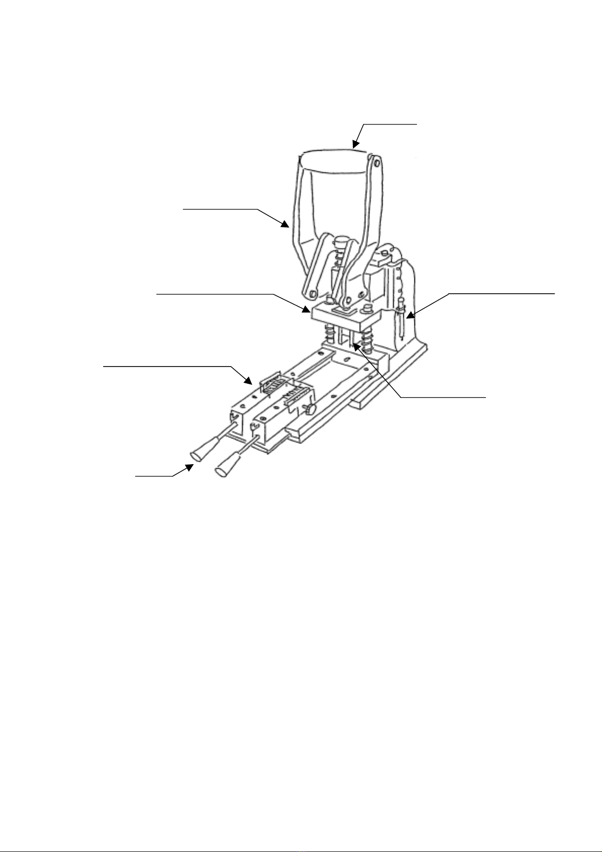
2.3. Tool Appearance and Unit Name...............................................................................2
3. Specifications
3.1. Tool Specifications......................................................................................................3
3.2. Outer Dimensions and Weight...................................................................................3
3.3. Operating Environment Conditions..........................................................................4
3.4. Installation Space.......................................................................................................4
4. Operation Method
4.1. Setting of Upper Cover...............................................................................................5
4.2. Setting of Cable..........................................................................................................6
4.3. Wire Arrangement......................................................................................................7
4.4. Wire Pushing and Cutting.........................................................................................8
5. Maintenance and Check
5.1. Daily Maintenance.....................................................................................................9
5.2. Check of Tool.............................................................................................................10
5.3. Exchange method of Wire Cut Blade and Wire Pusher..........................................11
5.4. Adjustment Method of Wire Pusher Bottom Dead Point .......................................12
5.5. Adjustment Method of Hand Press Bottom Dead Point.........................................13
6. Parts List
6.1. Wire Arrangement Unit Development ....................................................................14
6.2. Wire Pushing Unit Development.............................................................................15
6.2. Parts List..................................................................................................................16
7. Startup Checklist ...............................................................................................................18

A–1
<Safety Precautions>
Please read the following before operating the tool.
1. Introduction
Thank you for choosing our 1.0mm Pitch I/O Cable Wiring Tool.
This instruction manual is prepared so that the tool is properly used.
Please take the time to read this manual, making sure you understand the operating
procedures described herein before attempting to operate the tool.
2. To operation supervisors
1) Operators should fully understand the contents of this manual before operation.
2) If operators do not understand English, translate this manual into the proper language.
3) Keep this manual near the tool so that operators can refer to it anytime.
3. Dangerous operations
Observe the following precautions to prevent a life-threatening accident.
1) Don’t insert a part of your body or other foreign materials into the tool when you are using
the lever of a tool
2) Don’t place the tool on an unstable, off-balanced worktable from which the tool might fall
down.
3) If more than two operators are engaged in operation or checkup at the same time, even
slight miscommunication might lead to a serious accident.
Caution
1) Unauthorized reproduction of this document in part or in whole is prohibited.
2) The contents of this document are subject to change without notice.
3) Molex Japan Co., Ltd. assumes no responsibility for losses resulting from use or
misuse of this document.

A–2
<Safety Precautions>
Please read the following before operating the tool.
4. Careful handling
Keep the items below to use the tool safely and properly.
* Please contact our application-tooling group if something’s wrong with the tool.
1) Tool malfunctions
If you notice any unusual sound or movement in the tool, stop the operation
immediately and check the suspicious parts.
2) Foreign materials entering
If foreign materials such as water or metals accidentally get inside the tool, stop the
operation immediately and remove those materials.
5. Installation site
Be careful about the following items when you install the tool.
1) Temperature and humidity
Don’t operate the tool in extremely high/low temperature or extremely high humidity.
* Place it where the temperature is stable around 23 degrees centigrade and the air is
well ventilated.
2) Dust and corrosive gas
It will become the cause of failure if dust, corrosive gas, etc. are in the circumference of
this tool.
* Please don’t install this tool to such a place.
3) Unstable work table
When this tool is set up in an unbalance worktable, it not only becomes a dangerous
operation but also there is a case to cause the tool damage and it is dangerous.
* Please fix the tool on a stable table horizontally.

B–1
<Quality Precautions>
You surely carry out the following for defect-free production.
1. Introduction
In order not to produce a defective article with this tool, this chapter has described “Must
be carried out”, and “Must not be carried out” as an important matter on operation.
Keep in mind that there is a possibility that a defective article will be produced when not
protecting this.
2. Must be carried out
Please be sure to perform the following matter to maintain product quality.
1) Enforcement of startup check
Please check the tool in accordance with the “startup checklist” described in this
document before an operation start, and start operation after confirming nothing is
wrong with the tool.
* If the check is neglected, there is a possibility that a defective article will be
produced.
2) Confirmation of quality
Please start the production after confirming the quality of a product picked up from the
first operation, and it passes all of the claims required in the ITD (termination)
specifications and the I/O harness drawing of a corresponding connector.
* It is recommended to initiate the operation on the preferable condition that enough
margins for the standard are identified.
3. Must not be carried out
Please don’t perform the following matter by any means to maintain product quality.
1) Too much deeply pushing of wire
Pushing the wire to the upper cover too much deeply is a cause the damage of the
upper cover and it is a prohibition.
* Please work by an appropriate amount of the wire pushing.
2) Setting of upper cover in different direction
It is a prohibition because it causes the damage of the termination punch and the upper
cover when the upper cover is set in a direction different from a prescribed direction.
* Please set the upper cover in a prescribed direction and work.
3) Shear drop of conductor
The tool where shear drop of the conductor that exceeds the insulation outside
diameter of the wire has been occurred is dangerous for short-circuit and it is a
prohibition of use.
* Please work after the wire cut blade is exchanged and it puts it into the state without
shear drop of the conductor.

Page1
1. Description
This tool is a manual-wiring tool that is used to arrange the wire of I/O cable into the upper
cover as the pre-work of the termination of 1.0mm pitch I/O cable assembly of Molex.
As the procedure, the upper covers are set in the tool, and the wires in the cable are
arranged in the outside wire comb by the hand sequentially.
Next, the table is pushed in the tool, the wires are pushed and the batch is pushed into the
upper cover by depressing the handle of the tool. At that time, the excess wire is cut on the
upper cover edge.
2. Tool Configuration and Applicable Products
2.1. Tool Name and Configuration
1) Tool name:
1.0mm Pitch I/O Cable Wiring Tool
2) Tool number:
57859-5000: 10P Wiring Tool
57879-5000: 20P Wiring Tool
57849-5000: 26P Wiring Tool
57883-5000: 50P Wiring Tool
57874-5000: 68P Wiring Tool
3) Tool configuration:
(1) Wire arrangement unit:
Wire arrangement unit of wire to upper cover
(2) Wire pushing unit:
Wire pushing into upper cover and cutting of excess wire
(3) Hand press:
Toggle system hand press (Maximum termination force:
600kgf or more)
2.2. Applicable Connector and Cable
1) Connector:
1.0mm pitch I/O Connector (** = Circuit number)
52660-**11: 1.0mm pitch I/O **P plug assembly kit
(Plug+Uppercover)
2) Cable:
UL20276, AWG#28, Multi-pair braid shield cable, or other Molex
qualified cable, Wire insulation diameter = phi0.50- phi0.58 mm,
Cable outer diameter = phi7.0mm or less

Page2
2.3. Tool Appearance and Unit Name
Handle
Hand press
Wire trimming tool
Wire pushing unit
Wire arrangement unit
Wire pusher
Knob

Page3
3. Specifications
3.1. Tool Specifications
1) Arrangement of wire:
Wire is arranged one by one by with the hand in the prescribed
circuit number of the wire guide comb on the wire arrangement
unit that sets the upper cover.
2) Wire pushing:
The wire arrangement unit that completed the wire
arrangement is set in the tool, and pushing the wire into the
upper cover is executed by depressing the handle of the tool.
3) Cutting of excess wire:
The wire cut blade cuts the excess wire by the wire pushing
operation on the upper cover edge.
4) Setting of upper cover:
The concave mark of the upper cover is matched to the specified
position, and set it in the wire arrangement unit because there
is no directionality in the upper cover.
(The tool doesn’t have directionality either)
5) Setting of cable:
The sheath edge of the cable is matched to the cable stopper and
sets in the wire arrangement unit.
6) Standard circuit number
assignment:
The circuit number assignment of the standard is the following.
1
2
(N/2)-1
(N/2)
(N/2)+1
(N/2)+2
N-1
N
Cable
[Operator side]
Left Right Concave mark

Page4
3.2. Outer Dimensions and Weight
1) Outer dimensions:
180 (width) x 380 (depth) x 440 (height) mm
2) Weight:
Approx. 16 kgf
3.3. Operating Environment Conditions
1) Operating ambient temperature:
5- 35 degrees centigrade (Away from direct sunlight)
2) Operating ambient humidity:
35% - 85% RH (No condensation)
3) Operating atmosphere:
Atmosphere should be free of corrosive gases and
contaminants such as dust or lint.
3.4. Installation Space
Tool installation space on a worktable required for the purposes of performing operation
and maintenance checkups.
900 (width) x 900 (depth) x 1600 (height) mm

Page5
4. Operation Method
4.1. Setting of Upper Cover
1) Draw out the “wire arrangement unit (1)” from the main body of the tool to the operator
side.
2) Pull the “setting lever (2)” of the wire arrangement unit toward you, and set the “upper
cover (3)” between the “positioning plate (4)” and the “slide block (5)” in the prescribed
direction.
3) Next, release the “setting lever (2)” slowly and fix the “upper cover (3).”
“Note” The upper cover uses the concave mark for positioning because there is no directionality.
Setting Direction of 1.0mm Pitch Upper Cover
Positioning plate (4)
Upper cover (3)
Slide block ()
Set lever (2)
Wire arrangement unit (1)
1
2
(N/2)-1
(N/2)
(N/2)+1
(N/2)+2
N-1
N
Cable
[Operator side]
Left Right
Concave mark
Circuit number

Page6
4.2. Setting of Cable
1) Pull the “cable clamp knob (1)” of the wire arrangement unit in the direction of the outside,
and the clamper is held in the state of opening.
2) Put the “cable (2)” that has processed the edge side between the cable clamper.
3) Set the “copper foil tape edge (3)” of the cable under the cable stopper, and the cable is
clamped by releasing the “cable clamp knob (1).”
“Note” Please note that the size between the copper foil tape edge of the cable and the upper
cover changes at the position where the cable is set.
Copper foil taped edge (3)
Cable stopper (4)
Upper cover
Cable clamp knob (1)
Cable (2)

Page7
4.3. Wire Arrangement
1) Set a “wire (1)” in the ditch of a prescribed circuit number of the “wire guide comb (2)”
according to the wire arrangement table.
2) At this time, push the “wire (1)” firmly from both sides into the ditch of the “wire guide comb
(2)” while giving a tension light so that the wire should not slacken.
3) When the arrangement of all wires is finished, take the slack of the wire depressing an
“inside wire (4)” of the wire guide comb with the “wire arrangement tool (3).”
“Note” It is a prohibition because the wire pushing in the state that there is slack in the wire
causes a defective cutting. Please take the slack of the arranged wire surely.
Wire (1)
Wire guide comb (2)
Wire trimming tool (3)
Wire guide comb (2)
Inside wire (4)
Upper cover
Upper cover

Page8
4.4. Wire Pushing and Cutting
1) Grasp the “knob (2)” of a “wire arrangement unit (1)” by one hand and push it into the
interior of the “wire-pushing unit (3)” completely.
2) Depress the “handle (4)” of the “wire-pushing unit (3)” while the “knob (6)” of the wire
arrangement unit grasped by one hand, and the wire pushing and the cutting of the excess
wire are executed.
3) Draw out forward the “wire arrangement unit (1)” and remove the cut “wire scraps” from
the “wire guide comb (5).”
4) Remove the cable from the clamp pulling the “cable clamp knob (6).”
5) Next, incline the cable lightly back and forth after two “set levers (7)” are pulled at the same
time and the upper cover is put into the state of opening, and detach the cable assembly
from the “wire arrangement unit (1).”
“Note” Please put each hand on the “knob” and the “handle” without fail for safety and operate
it.
Handle (4)
Wire-pushing unit (3)
Wire guide comb (5)
Cable clamp knob (6)
Wire arrangement unit (1)
Set lever (7)
Knob (2)

Page9
5. Maintenance and Check
5.1. Daily Maintenance
1) Management of tool
Before a work start, please carry out the tool check in accordance with the “startup
checklist” in this manual, and start work after checking that it satisfies a standard.
* Please record each check result simultaneously.
2) Removal of foreign substances
Since foreign substances such as dust and wire scrap adheres to the “wire pushing blade,
“wire cut blade”, and “wire guide comb”, etc. during operation, please remove a foreign
substance timely.
* Neglect may become the cause of a defective wire arrangement.
3) Cleaning of work end
Please wipe with a dry cloth lightly after cleaning the tool with compression air every day
at the time of a work end. There is an effect that prevents rusting.
4) Lubrication
Please supply proper amount of “Lithium family grease” (JIS No. 2) to the shaft of a die
set and the ram of a hand press with the frequency of once a month.

Page10
5.2. Check of Tool
Please confirm the standard value with 1.0mm pitch I/O IDT (termination) specifications
of the latest version before it works.
1) Wire protruding length
It must be a standard value or less that the protruding length of the wire from the upper
cover edge.
<Standard> Wire protruding length = 0.3mm or less
2) Conductor shear drop
The amount of conductor shear drop of the cut wire shall be in the standard value or less,
and it is not short-circuited between pitches.
<Standard> Conductor shear drop amount = Within the outside diameter of the wire
insulation.
3) Scratch on wire insulation
There must not be remarkable scratch on the wire insulation with the wire guide comb
and the wire pusher, etc.
4) Damage of upper cover
There must not be remarkable damage to the upper cover with the wire pusher.
Upper cover
Conductor shear drop
Wire protruding length
Upper cover Wire

Page11
5.3. Exchange Method of Wire Cut Blade and Wire Pusher
1) [Exchange of wire cut blade]
The “wire cut blade (4)” can be removed below by removing the “M6 screw (2)” at the
center of the “cut blade holder (1)” of the wire pushing unit” and loosening the “fixed
screw (3).”
2) [Exchange of wire pusher]
The “cut blade holder (1)”, “wire cut blade (4)”, and “wire pusher (5)” come off from the
tool when the “fixed screw (3)” is removed.
“Note” Please note that the “internal compression spring” falls simultaneously with the wire
pusher when you exchange the pusher.
Cut blade holder (1)
M6 screw (2)
Fixed screw (3) Wire pusher (5) Wire cut blade (4)

Page12
5.4. Adjustment Method of Wire Pusher Bottom Dead Point
1) Loosen the “nut (2)” of the “shank (1)” on the hand press and adjust the bottom dead point of
the wire pusher turning the “shank (1).” Tighten the nut after it adjusts and the shank is
fixed to the “ram (3).”
2) Amount of adjustment and direction
[Amount of adjustment]
One scale = about 0.17mm (One rotation =1.0mm)
[Direction of adjustment]
The wire is deeply pushed: Shank is turned left.
The wire is shallowly pushed: Shank is turned right.
3) The “stopper (4)” is adjusted in the position with the space of 0.5mm from the “upper die set
(5)” at the bottom dead point of the tool.
* The stopper is for interference prevention of the upper and lower when the die set is
removed from the hand press.
“Note” Please start the work after confirming that the wires are surely pushed into the upper
cover without crushing after adjustment.
Shank (1)
Nut (2)
Ram (3)
Upper die set (4)
Stopper (5)

Page13
5.5. Adjustment Method of Hand Press Bottom Dead Point
When the adjustment of the bottom dead point is not good enough by the shank alone, the
bottom dead point of the main body of the hand press is adjusted according to the following
procedure.
1) Loosen the “fixed screw (2)” of the “handle block (1)” of the hand press and adjust the bottom
dead point of the main body of the hand press moving the handle block with the “adjustment
knob (3).”
2) Adjust the screw at the same time when there is a “support screw (4)” in the handle block.
3) Set the space of about 0.5mm at the bottom dead point position between the “upper die (6)”
and the “stopper (5).”
“Note” Please note that there is a case of the tool damage when the bottom dead point of the
main body of the hand press is adjusted low too much.
Handle block (1)
Fixed screw (2)
Stopper (5)
Support screw (4)
A
djustment knob (3)
Upper die (6)

Page14
6. Parts List
6.1. Wire Arrangement Unit Development (1.0mm pitch I/O Cable)
This manual suits for next models
4
Table of contents
Other molex Tools manuals

molex
molex 207129 Series User manual

molex
molex 63813-1400 User manual

molex
molex 64000-0041 User manual

molex
molex HT60923A User manual

molex
molex Mini Mi2 User manual

molex
molex 63813-2700 User manual

molex
molex RHT-5770 User manual

molex
molex 57834-5000 User manual

molex
molex 64005-0400 User manual

molex
molex 57147-6000 User manual
Popular Tools manuals by other brands

SW-Stahl
SW-Stahl 72375L instruction manual

Lincoln
Lincoln 3665 Assembly and operation guide

Dremel
Dremel 7350 Operating/safety instructions

jbc
jbc PH217 instruction manual

Hitachi
Hitachi G23SCY - 9 in. Anti-Vibration Angle Grinder Safety instructions

Kurt
Kurt CROSSOVER ANGLOCK VISE DX8 Operating instructions manual