Manual Press for SC Power
Order No: TM-640000041 Release Date: 05-02-13 UNCONTROLLED COPY Pa e 9 of 16
Revision: C Revision Date: 05-02-13
LOADED SCREW (2)
TOOLING
BASE PLATE
#8-32 BHCS (2)
Figure 2-2
TOOLING
ADJUSTING
SCREW
TOOLING
HOLDER
Operation
2 1 Installation
To secure the press, use a bench capable of
supportin at least 150 pounds (70k ), with
adequate li htin for easy operation. There are two
(2) holes for 5/16” la screws provided in the press
base for fastenin the press to the workbench. Be
sure there is adequate room around the press to
operate easily.
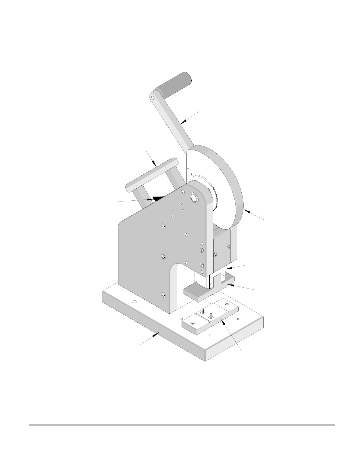
The 64000-0041 Complete Manual Press comes
with tool kit already installed. See Fi ure 2-1. If the
64000-0045 Tool Kit is not installed in the Press,
follow the steps below:
Upper Tooling
NOTE: Lowerin the press ram sli htly may assist
in installin the upper toolin .
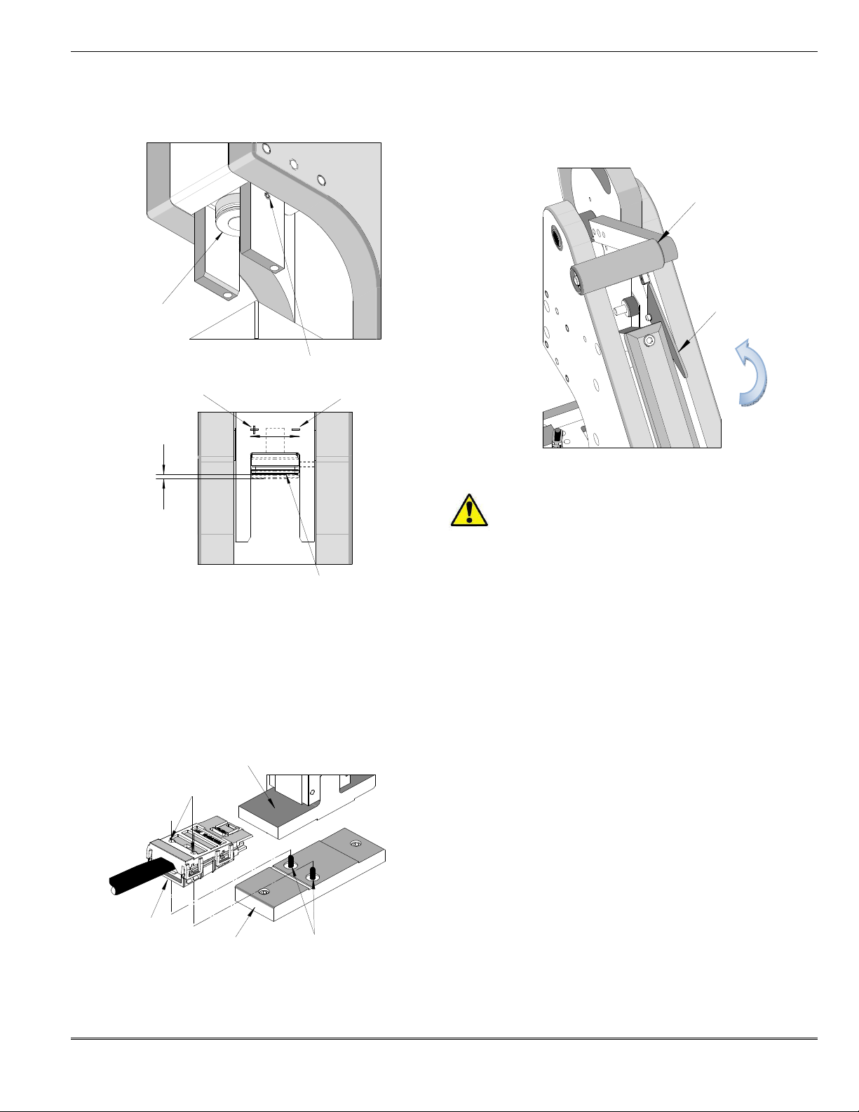
1. Slide the upper toolin holder with upper toolin ,
upward over the ram adjustin screw, until it
comes to a stop. See Fi ure 2-2.
2. Push the latch backward (away from the
operator). The upper toolin will now slide up
onto the ram an additional approximately 4.0mm
(0.16”).
3. Release the latch, the upper toolin will stay in
place.
Lower Tooling
1. Remove the two (2) sprin loaded screws with
the washers and sprin s on the base plate of
the Basic Press.
2. With the press ram in the up position, position
the lower toolin in the press.
3. Slide the lower toolin onto the base plate.
Fasten down with the (2) #8-32 BHCS
(Furnished with the tool kit). See Fi ure 2-3.
4. Slowly lower the press ram by pullin the press
lever forward and down.
5. Return the press ram to the full up position.
2 2 Set Up
The only setup required for this toolin is to adjust
the press ram stroke.
Ram Stroke Adjustment
1. Loosen the #8-32 set screw in the Ram which
locks the Ram Adjustin Screw into place. See
Fi ure 2-4.
2. There is an indicator en raved on the ram just
above the Ram Adjustin Screw. Turn the Ram
Adjustin Screw clockwise (CW) toward the “+”
si n to increase the ram stroke. To decrease
the stroke, turn the Ram Adjustin Screw
counterclockwise (CCW) toward the “-” si n.
Stroke adjustment controls the shut hei ht of the
connector assembly. Ram stroke is set so that
the connector measures a specific shut hei ht
when terminated. See Product Specifications