ELECTRONICS FOR SPECIALISTS ELECTRONICS FOR SPECIALISTS ELECTRONICS FOR SPECIALISTS ELECTRONICS FOR SPECIALISTS ELECTRONICS FOR SPECIALISTS ELECTRONICS FOR SPECIALISTS ELECTRONICS FOR
MONACOR INTERNATIONAL GmbH & Co. KG • Zum Falsch 36 • 28307 Bremen • Germany Copyright©by MONACOR INTERNATIONAL. All rights reserved. A-1443.99.03.03.2021
12 – 24 V
+COM
RED
GREEN
BLUE
INPUT
WHITE
12 – 24 V
V+
W
B
G
R
BG R
W
OUTPUT INPUT
12-24 V
44 A MAX.
POWER
ON
➀
+COM
+COM
WHITE
WHITE
+COM
+COM
GREEN
GREEN
+COM
+COM
RED
RED
OUTPUT
BLUE
BLUE
+COM
+COM
I1 RGBW
10
A max.
V+
W
B
G
R
V+
W
B
G
R
I2 RGBW
10
A max.
➁
+COM
+COM
WHITE
WHITE
+COM
+COM
GREEN
GREEN
+COM
+COM
RED
RED
OUTPUT
BLUE
BLUE
+COM
+COM
I1 + I2 + I3 + I4 + I5 + I6 + I7 + I8 = 44
A max.
1
10
A max.
I2
10
A max.
I3
10
A max.
I4
10
A max.
I5
10
A max.
I6
10
A max.
I7
10
A max.
I8
10
A max.
V+
V−
V+
V−
V+
V−
V+
V−
V+
V−
V+
V−
V+
V−
V+
V−
wit
blanco
blauw
azul
groen
verde
rood
rojo
➂
CU-4BOOST
Bestelnr. • Ref. Núm. 0386520
Booster de LEDs
Estas instrucciones van dirigidas a
usuarios con conocimientos básicos
de electrónica. Lea atentamente estas
instrucciones antes de utilizar el apa-
rato y guárdelas para usos posteriores.
1 Aplicaciones
El amplificador CU-4BOOST para 4 canales
de color se necesita cuando la potencia del
controlador de LEDs no es suficiente para
las tiras de LEDs o los módulos de LEDs
que hay que conectar. Hay que insertar el
amplificador justo después del controlador.
LosLEDs han de tener un voltaje de funcio-
namiento entre ⎓12V y ⎓24 V, y el contro-
lador ha de tener modulación por ancho de
pulsos (p.ej. el CU-4DMX).
2 Notas Importantes
El aparato cumple con todas las directivas
relevantes de la UE y por lo tanto está mar-
cado con el símbolo .
•
El aparato está adecuado sólo para utili-
zarlo en interiores. Protéjalo de la hume-
dad y del calor (temperatura ambiente
admisible: 0– 40°C).
•
Utilice sólo un paño suave y seco para
la limpieza; no utilice nunca ni agua ni
productos químicos.
•
No podrá reclamarse garantía o respon-
sabilidad alguna por cualquier daño per-
sonal o material resultante si el aparato
se utiliza para otros fines diferentes a los
originalmente concebidos, si no se co-
necta adecuadamente, si se sobrecarga
o no se repara por expertos.
Si el aparato se va a dejar fuera
de servicio definitivamente, des-
hágase del aparato según las
normativas locales.
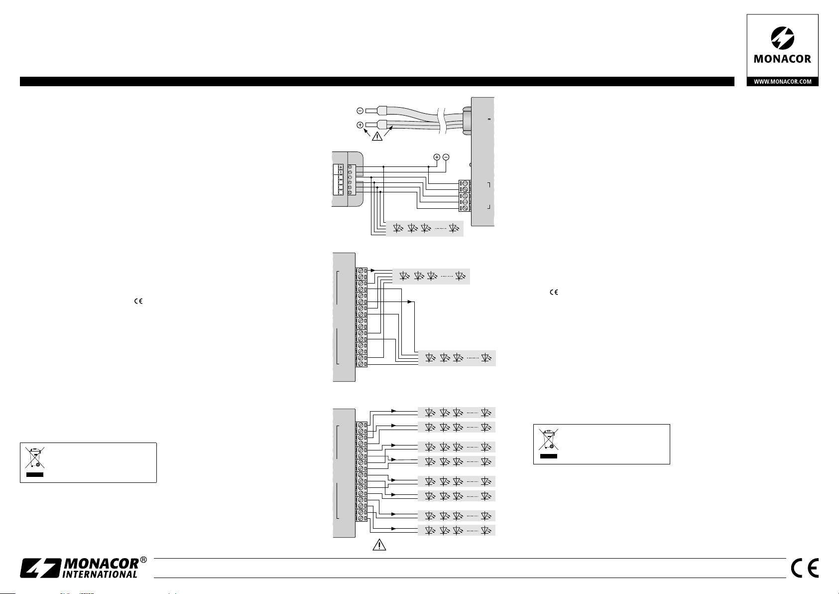
3 Conexión
Se pueden extraer todos los terminales
para una conexión más sencilla.
1) Conecte las salidas del controlador que
se van a utilizar para los LEDs a los ter-
minales INPUT del CU-4BOOST: Conecte
las salidas para Rojo, Verde, Azul y
Blanco a los terminales de entrada RED,
GREEN, BLUE y WHITE y el polo positivo
común al terminal +COM. Como ejem-
plo, en la figura 1 se ilustra la conexión
del controlador CU-4DMX.
2) Conecte los LEDs a los terminales OUT-
PUT:
2 × WHITE = conexiones negativas del Blanco
2 × RED = conexiones negativas del Rojo
2 × GREEN = conexiones negativas del Verde
2 × BLUE = conexiones negativas del Azul
8 × +COM = conexiones positivas
Recuerde siempre que: La potencia
máxima de cada terminal de salida es de
10A. La potencia total del CU-4BOOST,
sin embargo, no puede exceder los 44A.
Como ejemplo, la figura 2 ilustra la co-
nexión de 2 tiras de LEDs RGBW, y la
figura 3 ilustra la conexión de 8 tiras de
LEDs monocromas.
3) Se necesita un alimentador regulado
para la alimentación. El alimentador
tiene que poder enviar la potencia ne-
cesaria para hacer funcionar los LEDs
conectados. Ajuste el alimentador con
el voltaje de funcionamiento de los LEDs
(mín. ⎓12V, máx. ⎓24 V). Conecte el
cable de alimentación del CU-4BOOST
al alimentador. ¡Conecte el conductor
marcado al polo positivo del alimenta-
dor! En cuanto se aplique el voltaje de
funcionamiento, el LED POWER ON se
iluminará y el amplificador está listo para
funcionar.
4 Especificaciones
Potencia:. . . . . . . . . 10A máx. por cada
terminal,
un total de 44A máx.
Voltaje de
funcionamiento: . . . ⎓12–24V (depen-
diendo de los LEDs)
Cable de conexión: 1 m, 2 × 6 mm
2
Corriente de reposo: 10 mA
Dimensiones: . . . . . 106 × 38 × 128mm
Peso:. . . . . . . . . . . . 460g
Sujeto a modificaciones técnicas.
Ledbooster
Deze handleiding is bedoeld voor
gebruikers met basiskennis van elek-
tronica. Lees de handleiding grondig
door, alvorens het apparaat in gebruik
te nemen, en bewaar ze voor latere
raadpleging.
1 Toepassingen
De versterker CU-4BOOST voor 4 kleuren-
kanalen is nodig, als de belastbaarheid van
het gebruikte ledbesturingsapparaat voor
de aan te sluiten ledstroken of ledmodu-
les ontoereikend is. Hij wordt onmiddellijk
na het besturingsapparaat geschakeld.
Deled’s moeten met een bedrijfsspanning
van ⎓12V tot ⎓24V werken en het be-
sturingsapparaat (bv.CU-4DMX) met een
pulsbreedtemodulatie.
2 Belangrijke gebruiksvoorschriften
Het apparaat is in overeenstemming met
alle relevante EU-Richtlijnen en draagt
daarom de -markering.
•
Het apparaat is enkel geschikt voor ge-
bruik binnenshuis; vermijd uitzonderlijk
warme plaatsen en plaatsen met hoge
vochtigheid (toegestaan omgevingstem-
peratuurbereik 0 – 40 °C).
•
Verwijder het stof enkel met een droge
doek. Gebruik zeker geen chemicaliën
of water.
•
In geval van ongeoorloofd gebruik, fou-
tieve aansluiting, overbelasting of van
herstelling door een niet-gekwalificeerd
persoon vervalt de garantie en de aan-
sprakelijkheid voor hieruit resulterende
materiële of lichamelijke schade.
Wanneer het apparaat definitief uit
bedrijf wordt genomen, bezorg het
dan voor milieuvriendelijke verwer-
king aan een plaatselijk recyclage-
bedrijf.
3 Aansluiting
U kunt elke klem afnemen om het aanslui-
ten te vereenvoudigen.
1) Verbind de voor de led’s voorziene uit-
gangen op het besturingsapparaat met
de klemmen INPUT van CU-4BOOST: de
uitgangen voor rood, groen, blauw en
wit met de respectieve ingangsklem-
men RED, GREEN, BLUE en WHITE en
de gemeenschappelijke positieve pool
met de klem +COM. Figuur 1 geeft als
voorbeeld de aansluiting van het bestu-
ringsapparaat CU-4DMX.
2) Verbind de led’s met de klemmen OUT-
PUT:
2 × WHITE = negatieve aansluitingen wit
2 × RED = negatieve aansluitingen rood
2 × GREEN = negatieve aansluitingen groen
2 × BLUE = negatieve aansluitingen blauw
8 × +COM = positieve aansluitingen
Let in elk geval op het volgende: Elke
uitgangsklem is met maximum 10A
belastbaar. De totale belasting van de
CU-4BOOST mag echter niet hoger lig-
gen dan 44A.
Figuur2 toontdeaansluitingvan 2RGBW-
ledstroken, figuur 3 de aansluiting van
8individuele ledstroken.
3) Voor de voedingsspanning gebruikt u
een gestabiliseerde netadapter. Hij moet
de stroom kunnen leveren die nodig is
om de aangesloten led’s te doen bran-
den. Stel de netadapter in op de be-
drijfsspanning van de led’s (min. ⎓12V,
max. ⎓24V). Verbind de voedingskabel
van de CU-4BOOST met de netadapter.
Verbind de gemarkeerde ader met de
positieve pool van de netadapter! Zodra
de bedrijfsspanning is aangesloten, licht
de led POWER ON op en is de versterker
bedrijfsklaar.
4 Technische gegevens
Belastbaarheid: . . . per klem max. 10 A,
in totaal max. 44A
Voedingsspanning: ⎓12 – 24 V (afhanke-
lijk van de led’s)
Aansluitkabel: . . 1 m, 2 × 6 mm2
Ruststroom: . . . . . 10 mA
Afmetingen: . . . . . 106 × 38 × 128 mm
Gewicht:. . . . . . . . 460g
Wijzigingen voorbehouden.
Nederlands
Español