manuals.online logo
Brands
  1. Home
  2. •
  3. Brands
  4. •
  5. Monacor
  6. •
  7. Speakers System
  8. •
  9. Monacor PA ESP-232/SW User manual

Monacor PA ESP-232/SW User manual

®
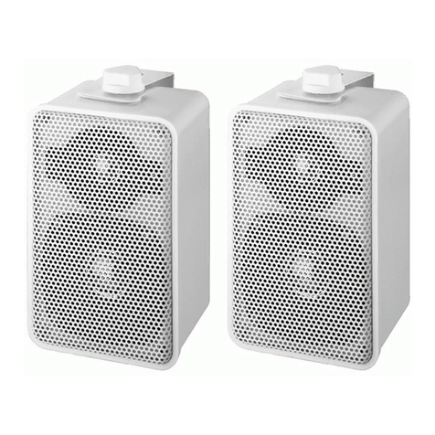
ELA-Lautsprecherbox für
100-V- oder 8-Ω-Betrieb
Bitte lesen Sie diese Anleitung vor der Installation
gründlich durch und heben Sie sie für ein späteres
Nachlesen auf.
1 Verwendungsmöglichkeiten
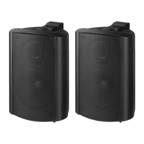
Diese 2-Wege-Lautsprecherbox zur Wandmon-
tage ist speziell für den Einsatz in Beschallungsan-
lagen konzipiert. Sie ist mit einem Übertrager für
den Betrieb in 100-V-Anlagen ausgestattet, kann
aber auch direkt an einen niederohmigen Verstär-
kerausgang angeschlossen werden. Die Lautspre-
cherbox ist wetterfest (IP 55) und kann darum auch
im Außenbereich eingesetzt werden.
2 Wichtige Hinweise für den Gebrauch
Die Lautsprecherbox entspricht allen erforderli-
chen Richtlinien der EU und ist deshalb mit
gekennzeichnet.
G
Schützen Sie die Lautsprecherbox vor großer
Hitze und Kälte (zulässiger Einsatztemperaturbe-
reich 0 – 40 °C).
GVerwenden Sie zum Reinigen nur ein trockenes,
oder angefeuchtetes, weiches Tuch, auf keinen
Fall aggressive Reinigungsmittel oder Chemi-
kalien.
GWird die Lautsprecherbox zweckentfremdet,
nicht fachgerecht montiert, falsch angeschlos-
sen oder überlastet, kann keine Haftung für
daraus resultierende Sach- oder Personenschä-
den und keine Garantie für die Lautsprecherbox
übernommen werden.
3 Installation
WARNUNG Beim Betrieb in 100-V-Anlagen liegt
berührungsgefährliche Spannung bis
100 V an der Lautsprecherleitung an.
Die Installation darf nur durch Fach-
personal erfolgen.
Achten Sie auf die Belastung des ELA-Verstärkers
durch die Lautsprecher. Eine Überlastung kann
den Verstärker beschädigen! Die Summe der
Leistungen aller angeschlossenen Lautsprecher
darf die Verstärkerleistung nicht überschreiten.
Soll die Lautsprecherbox endgültig aus
dem Betrieb genommen werden, überge-
ben Sie sie zur umweltgerechten Entsor-
gung einem örtlichen Recyclingbetrieb.
1) Vor der Installation der Lautsprecherbox den
ELA-Verstärker ausschalten, damit die Laut-
sprecherleitung spannungsfrei ist!
2) Zur Wandmontage den Montagebügel von der
Lautsprecherbox abschrauben und den Bügel
an gewünschter Stelle der Wand befestigen.
3) Die gewünschte Nennbelastung (Lautstärke) mit
dem Schalter auf der Rückseite einstellen oder
beim Betrieb an einem niederohmigen
Verstärkerausgang den Schalter in
die Position „8 Ω“ drehen.
VORSICHT! In der Position „8 Ω“ den Lautspre-
cher auf keinen Fall in einer 100-V-Anlage be-
treiben. Der Lautsprecher und eventuell auch
der Verstärker werden beschädigt.
4) Die Lautsprecherbox über die Anschlussklem-
men an den ELA-Verstärker anschließen. Beim
Anschluss von mehreren Lautsprechern darauf
achten, dass die Lautsprecher alle gleich gepolt
werden (z. B. schwarze Klemme = Minuspol).
5) Die Lautsprecherbox an dem Montagebügel
festschrauben und optimal auf den zu beschal-
lenden Bereich ausrichten.
Änderungen vorbehalten.
PA Speaker System for 100 V
Operation or 8 Ω Operation
Please read these operating instructions carefully
prior to the installation and keep them for later ref-
erence.
1 Applications
This 2-way speaker system for wall mounting is
especially designed for applications in PA systems.
It is equipped with a transformer for operation in
100 V systems, but it can also directly be con-
nected to a low-impedance amplifier output. The
speaker system is weatherproof (IP 55) and is
therefore also suitable for outdoor applications.
2 Important Notes
The speaker system corresponds to all required
directives of the EU and is therefore marked with .
GProtect the speaker system against excessive
heat and cold (admissible ambient temperature
range 0 – 40 °C).
GFor cleaning only use a soft cloth, dry or slightly
damp, never use aggressive detergents or
chemicals.
GNo guarantee claims for the speaker system and
no liability for any resulting personal damage or
material damage will be accepted if the speaker
system is used for other purposes than originally
intended, if it is not correctly installed or con-
nected, or if it is overloaded.
3 Installation
1) Prior to the installation of the speaker system
switch off the PA amplifier completely, so that
the speaker cable will not carry any voltage!
WARNING During operation, there is a hazard of
contact with a voltage of up to 100 V
at the speaker cable. The installation
must be carried out by skilled per-
sonnel only.
Observe the load of the PA amplifier by the speak-
ers. An overload may damage the amplifier! The
total power of all speakers connected must not
exceed the amplifier power.
If the speaker system is to be put out of
operation definitively, take it to a local
recycling plant for a disposal which is not
harmful to the environment.
2) For wall mounting, screw off the mounting
bracket from the speaker system and fix the
bracket at the desired place of the wall.
3) Adjust the desired rated load (volume) with the
switch on the rear side or turn the
switch to position “8 Ω” when operating
at a low-impedance amplifier output.
CAUTION! In position “8 Ω” never use the
speaker in a 100 V system. The speaker and
possibly the amplifier will be damaged.
4) Connect the speaker system via the connecting
terminals to the PA amplifier. When connecting
several speakers, make sure that all speakers
have the same polarity (e. g. black terminal =
negative pole).
5) Tightly screw the speaker system at the mount-
ing bracket and align it in an optimum way to the
area where the sound is to be directed.
Subject to technical modification.
ESP-232/SW Bestell-Nr. 16.2600
ESP-232/WS Bestell-Nr. 16.2610
MONACOR INTERNATIONAL GmbH & Co. KG • Zum Falsch 36 • 28307 Bremen • Germany
Copyright©by MONACOR INTERNATIONAL. All rights reserved. A-1152.99.02.05.2011
®
D A CH
GB
Technische Daten Specifications ESP-232/…
Nennbelastbarkeit bei 100-V-Betrieb Power rating with 100 V operation 30/20/10/5 WRMS
Belastbarkeit bei 8-Ω-Betrieb Rating with 8 Ω operation 50 WMAX/30 WRMS
Frequenzbereich Frequency range 75 – 20 000 Hz
Mittlerer Schalldruck (1 W/1 m) SPL (1 W/1 m) 89 dB
Gehäuseschutzart Protective class of housing IP 55
Abmessungen Dimensions 160 × 260 × 180 mm
Gewicht Weight 2,3 kg
®
Enceinte Public Adress
pour fonctionnement
100 V ou 8 Ω
Veuillez lire la présente notice avec attention avant
lʼinstallation et conservez-la pour pouvoir vous y
reporter ultérieurement.
1 Possibilités dʼutilisation
Cette enceinte 2 voies pour montage mural est
spécialement conçue pour une utilisation dans des
installations de sonorisation. Elle est dotée dʼun
transformateur pour fonctionnement dans des instal-
lations 100 V, elle peut également être directement
reliée à une sortie amplificateur basse impédance.
Lʼenceinte est protégée contre les intempéries
(IP 55) et peut donc être utilisée en extérieur.
2 Conseils importants dʼutilisation
Lʼenceinte répond à toutes les directives néces-
saires de lʼUnion européenne et porte donc le sym-
bole .
G
Protégez lʼenceinte dʼune chaleur élevée et du
froid (température ambiante admissible 0 –40°C).
GPour le nettoyage, utilisez uniquement un chiffon
sec ou légèrement humide, et doux, en aucun
cas de détergents agressifs ou produits chi-
miques.
G
Nous déclinons toute responsabilité en cas de
dommages matériels ou corporels résultants si
lʼenceinte est utilisée dans un but autre que celui
pour lequel elle a été conçue, si elle nʼest pas cor-
rectement montée ou branchée ou sʼil y a sur-
charge ; en outre, la garantie deviendrait caduque.
3 Installation
AVERTISSEMENT Pendant le fonctionnement, une
tension de contact dangereuse
jusquʼà 100 V est présente au
câble haut-parleur. Seul un per-
sonnel qualifié peut effectuer
lʼinstallation.
Faites attention à la charge de lʼamplificateur PA
par les haut-parleurs. Une surcharge peut en-
dommager lʼamplificateur. La somme des puis-
sances de lʼensemble des enceintes reliées ne
doit pas dépasser la puissance de lʼamplificateur.
Lorsque lʼenceinte est définitivement reti-
rée du service, vous devez la déposer dans
une usine de recyclage adaptée pour
contribuer à son élimination non polluante.
1) Avant dʼinstaller lʼenceinte, éteignez lʼamplifica-
teur Public Adress pour que le câble haut-par-
leur ne soit pas porteur de tension !
2) Pour un montage mural, dévissez lʼétrier de
montage de lʼenceinte et fixez lʼétrier à lʼendroit
voulu sur le mur.
3) Réglez la puissance nominale souhaitée
(volume) avec lʼinterrupteur sur la face arrière
ou, pour un fonctionnement à une
sortie ampli basse impédance, tour-
nez le sélecteur sur la positon “8 Ω”.
ATTENTION ! En position “8 Ω”, ne faites pas
fonctionner lʼenceinte dans une installation
100 V. Lʼenceinte, voire lʼamplificateur, pour-
raient être endommagés.
4) Reliez lʼenceinte via les bornes à pinces à lʼam-
plificateur Public Adress. Si vous branchez plu-
sieurs enceintes, veillez à ce quʼelles aient
toutes la même polarité (par exemple pince
noire = pôle moins).
5) Vissez lʼenceinte sur lʼétrier de montage et
orientez-le de manière optimale vers la zone à
sonoriser.
Tout droit de modification réservé.
Cassa acustica PA
per 100 V o 8 Ω
Vi preghiamo di leggere attentamente le presenti
istruzioni prima dellʼinstallazione e di conservarle
per un uso futuro.
1 Possibilità dʼimpiego
Questa cassa acustica a 2 vie per montaggio alla
parete è stata realizzata specialmente per lʼimpiego
in impianti di sonorizzazione. È equipaggiata con un
trasformatore per il funzionamento in impianti con
uscita audio 100 V, ma può essere collegata anche
con unʼuscita a bassa impedenza dellʼamplificatore.
La cassa è resistente alle intemperie (IP 55), e per-
tanto può essere impiegata anche allʼesterno.
2 Avvertenze importanti per lʼuso
La cassa acustica è conforme a tutte le direttive
richieste dellʼUE e pertanto porta la sigla .
GProteggere la cassa acustica da alto calore
e freddo (temperatura dʼimpiego ammessa fra
0 e 40 °C).
GPer la pulizia usare solo un panno morbido,
asciutto o inumidito; non impiegare in nessun
caso detergenti aggressivi o prodotti chimici.
G
Nel caso dʼuso improprio, di montaggio sbagliato,
di collegamento scorretto o di sovraccarico della
cassa acustica, non si assume nessuna respon-
sabilità per eventuali danni consequenziali a per-
sone o a cose e non si assume nessuna garan-
zia per la cassa acustica.
3 Installazione
AVVERTIMENTO Durante il funzionamento in im-
pianti a 100 V, nel cavo per alto-
parlanti è presente una tensione
fino a 100 V, pericolosa in caso di
contatto. Lʼinstallazione deve es-
sere eseguita solo da personale
specializzato.
Tener presente anche il carico dellʼamplificatore
PA da parte degli altoparlanti. Un sovraccarico
può danneggiare lʼamplificatore! La somma delle
potenze di tutti gli altoparlanti collegati non deve
superare la potenza dellʼamplificatore.
Se si desidera eliminare la cassa acustica
definitivamente, consegnarla per lo smal-
timento ad unʼistituzione locale per il rici-
claggio.
1) Prima dellʼinstallazione della cassa acustica, spe-
gnere lʼamplificatore PA perché la linea per alto-
parlanti sia completamente esente da tensione!
2) Per il montaggio alla parete svitare la staffa di
montaggio dalla cassa e fissare la staffa nel
punto desiderato della parete.
3) Con il selettore sul retro impostare la potenza
nominale (il volume) richiesta oppure, in caso di
collegamento con unʼuscita a bassa
impedenza dellʼamplificatore, girare il
selettore in posizione “8 Ω”.
ATTENZIONE! In posizione “8 Ω”, non usare in
nessun caso lʼaltoparlante in un impianto con
uscita audio 100 V. Lʼaltoparlante e eventual-
mente anche lʼamplificatore subiranno dei danni.
4) Collegare la cassa acustica con lʼamplificatore
PA per mezzo dei morsetti di collegamento. Col-
legando più altoparlanti, fare attenzione affinché
tutti abbiano la stessa polarità (p. es. conduttore
nero = polo negativo).
5) Avvitare la cassa alla staffa di montaggio e
orientarla in modo ottimale verso la zona da
sonorizzare.
Con riserva di modifiche tecniche.
ESP-232/SW Bestell-Nr. 16.2600
ESP-232/WS Bestell-Nr. 16.2610
MONACOR INTERNATIONAL GmbH & Co. KG • Zum Falsch 36 • 28307 Bremen • Germany
Copyright©by MONACOR INTERNATIONAL. All rights reserved. A-1152.99.02.05.2011
®
F
I
B CH
Caractéristiques techniques Dati tecnici ESP-232/…
Puissance nominale pour fonctionnement 100 V
Potenza nominale con 100 V 30/20/10/5 WRMS
Charge admissible pour fonctionnement 8 Ω Potenza con 8 Ω 50 WMAX/30 WRMS
Bande passante Gamma di frequenze 75 – 20 000 Hz
Pression sonore moyenne (1 W/1 m) Pressione sonora media (1 W/1 m) 89 dB
Classe de protection du boîtier Grado di protezione del contenitore IP 55
Dimensions Dimensioni 160 × 260 × 180 mm
Poids Peso 2,3 kg
®
Recinto de Megafonía para Fun-
cionamiento en 100 V o en 8 Ω
Lea atentamente estas instrucciones de funciona-
miento antes de la instalación y guárdelas para
posteriores usos.
1 Aplicaciones
Este recinto de 2 vías para montaje en pared está
diseñado especialmente para aplicaciones siste-
mas de megafonía. Está equipado con un transfor-
mador para funcionar en sistemas de 100 V pero
también puede conectarse directamente a una
salida de amplificador de baja impedancia. El
recinto está impermeabilizado (IP 55) y por lo tanto
se puede utilizar también en exteriores.
2 Notas Importantes
El recinto cumple con todas las directivas requeri-
das por la UE y por lo tanto está marcado con el
símbolo .
GProteja el recinto del calor y del frío excesivo
(temperatura ambiente admisible: 0 – 40 ºC).
GUtilice sólo un paño suave, seco o ligeramente
humedecido para la limpieza; no utilice nunca
productos químicos o detergentes agresivos.
GNo podrá reclamarse garantía o responsabilidad
alguna por cualquier daño personal o material
producido si se utiliza el recinto para fines dife-
rentes a los originalmente concebidos, si no se
conecta o se instala correctamente, o si se so-
brecarga.
3 Instalación
ADVERTENCIA Durante el funcionamiento, existe
el peligro de contacto con un vol-
taje de hasta 100 V en el cable de
altavoz. La instalación tiene que
llevarse a cabo sólo por el persona
cualificado.
Observe la carga del amplificador de megafonía
en los altavoces. ¡Una sobrecarga puede dañar el
amplificador! La potencia total de todos los alta-
voces conectados no puede sobrepasar la poten-
cia del amplificador.
Si va a poner el recinto fuera de servicio
definitivamente, llévelo a la planta de reci-
claje más cercana para que su eliminación
no sea perjudicial para el medioambiente.
1) Antes de la instalación del recinto, desconecte
el sistema de megafonía completamente de
modo que el cable de altavoz no contenga nin-
gún voltaje.
2) Para el montaje en pared, desenrosque el
soporte de montaje del recinto y fije el soporte
en el lugar de la pared que usted prefiera.
3) Ajuste el nivel de carga que prefiera (volumen)
con el interruptor de la parte posterior o gire el
interruptor hasta la posición “8 Ω”
cuando utilice una salida de amplifi-
cador de baja impedancia.
¡ADVERTENCIA! No utilice nunca un altavoz
que esté en la posición “8 Ω” en un sistema de
100 V. Se dañaría el altavoz y posiblemente el
amplificador.
4) Conecte el recinto mediante los terminales de
conexión al amplificador de megafonía. Cuando
conecte varios altavoces, asegúrese de que
todos los altavoces tienen la misma polaridad
(p. ej. terminal negro = polo negativo).
5) Atornille con firmeza el recinto en el soporte de
montaje y diríjalo correctamente hacia la zona a
la que hay que dirigir el sonido.
Sujeto a modificaciones técnicas.
Zestawy głośnikowe PA
do pracy 100 V oraz 8 Ω
Przed rozpoczęciem użytkowania prosimy o zapo-
znanie się z instrukcją i zachowanie jej do wglądu.
1 Zastosowanie
Niniejsze, 2-drożne naścienne zestawy głośni-
kowe przeznaczone są do pracy w systemach PA.
Wyposażone są w transformator do pracy w syste-
mach 100 V, ale mogą również pracować ze
wzmacniaczami niskoomowymi. Dzięki obudowom
odpornym na warunki atmosferyczne (IP 55) mogą
pracować na zewnątrz.
2 Środki bezpieczeństwa
Zestawy głośnikowe spełniają wszystkie wymaga-
nia norm UE dzięki temu zostały oznaczone sym-
bolem .
GNależy chronić je przez wysokimi i niskimi tem-
peraturami (dopuszczalny zakres 0 – 40 °C).
GDo czyszczenia należy używać suchej lub zwil-
żonej i miękkiej ściereczki, nie używać silnych
środków chemicznych.
GProducent i dostawca nie ponoszą odpowie-
dzialności za powstałe szkody: uszkodzenia
sprzętu bądź obrażenia użytkownika, jeżeli
zestawy głośnikowe były używane niezgodnie z
przeznaczeniem, niepoprawnie zainstalowane,
podłączone lub przeciążone.
3 Instalacja
1) Przed przystąpieniem do podłączania głośni-
ków należy odłączyć zasilanie wzmacniacza,
UWAGA W czasie pracy, na złączach wystę-
puje niebezpieczne wysokie napięcie
100 V. Instalacja powinna być wyko-
nywana wyłącznie przez osoby prze-
szkolone.
Należy zwrócić uwagę na obciążenie wzmacnia-
cza przez głośniki. Przeciążenie wzmacniacza
spowoduje jego uszkodzenie! Sumaryczna moc
głośników nie może przekraczać mocy wzmac-
niacza.
Jeśli zestaw głośnikowy nie będzie już wię-
cej używany, wskazane jest przekazanie
go do miejsca utylizacji odpadów, aby zos-
tał zniszczony bez szkody dla środowiska.
aby kabel głośnikowy 100 V nie znajdował się
pod napięciem!
2) Przed przystąpieniem do montażu na ścianie,
odkręcić uchwyt montażowy od zestawu głośni-
kowego i przymocować go do ściany w odpo-
wiednim miejscu.
3) Ustawić żądaną moc (głośność) za pomocą
przełącznika na tylnym panelu, lub
ustawić go na pozycję “8 Ω” w przy-
padku pracy ze wzmacniaczem
niskoomowym.
UWAGA! Po ustawieniu pozycji “8 Ω” nie wolno
podłączać zestawu głośnikowego do wzmacnia-
cza 100 V, gdyż ulegnie on uszkodzeniu.
4) Podłączyć głośnik do systemu PA za pomocą
terminali. Przy podłączaniu kilku głośników,
należy zwrócić uwagę, aby wszystkie głośniki
miały jednakową polaryzację (np. czarny termi-
nal = ujemny biegun).
5) Założyć zestaw głośnikowy na uchwyt i przykrę-
cić ustawiając w optymalnej pozycji do nagłaś-
niającego obszaru.
Z zastrzeżeniem możliwości zmian.
ESP-232/SW Bestell-Nr. 16.2600
ESP-232/WS Bestell-Nr. 16.2610
MONACOR INTERNATIONAL GmbH & Co. KG • Zum Falsch 36 • 28307 Bremen • Germany
Copyright©by MONACOR INTERNATIONAL. All rights reserved. A-1152.99.02.05.2011
®
E
PL
Especificaciones Specyfikacja ESP-232/…
Potencia nominal en modo 100 V Moc przy pracy 100 V 30/20/10/5 WRMS
Potencia en modo 8 Ω Moc przy pracy 8 Ω 50 WMAX/30 WRMS
Banda pasante Pasmo przenoszenia 75 – 20 000 Hz
SPL (1 W/1 m) SPL (1 W/1 m) 89 dB
Clase de protección de la carcasa Klasa szczelności obudowy IP 55
Dimensiones Wymiary 160 × 260 × 180 mm
Peso Waga 2,3 kg

This manual suits for next models

3

Other Monacor Speakers System manuals

Monacor DN-4 User manual

Monacor

Monacor DN-4 User manual

Monacor EAM-17DT User manual

Monacor

Monacor EAM-17DT User manual

Monacor ETS-530TW/SW User manual

Monacor

Monacor ETS-530TW/SW User manual

Monacor img Stage Line PROTON-15MK2 User manual

Monacor

Monacor img Stage Line PROTON-15MK2 User manual

Monacor EDL-606 User manual

Monacor

Monacor EDL-606 User manual

Monacor MKA-60/WS User manual

Monacor

Monacor MKA-60/WS User manual

Monacor DNL-660 User manual

Monacor

Monacor DNL-660 User manual

Monacor ETS-115/SI User manual

Monacor

Monacor ETS-115/SI User manual

Monacor EDL-110/WS User manual

Monacor

Monacor EDL-110/WS User manual

Monacor PAB-82WP/WS User manual

Monacor

Monacor PAB-82WP/WS User manual

Monacor ESP-1000AB⁄ WS User manual

Monacor

Monacor ESP-1000AB⁄ WS User manual

Monacor EDL-224AB User manual

Monacor

Monacor EDL-224AB User manual

Monacor ETS-515TW/SW User manual

Monacor

Monacor ETS-515TW/SW User manual

Monacor ETS-515TW/SW User manual

Monacor

Monacor ETS-515TW/SW User manual

Monacor ESP-63/ WS User manual

Monacor

Monacor ESP-63/ WS User manual

Monacor EUL-30/SW User manual

Monacor

Monacor EUL-30/SW User manual

Monacor ETS-215/WS User manual

Monacor

Monacor ETS-215/WS User manual

Monacor ESP-415-WS User manual

Monacor

Monacor ESP-415-WS User manual

Monacor EDL-24 User manual

Monacor

Monacor EDL-24 User manual

Monacor EX-1W User manual

Monacor

Monacor EX-1W User manual

Monacor ESP-5HQ User manual

Monacor

Monacor ESP-5HQ User manual

Monacor EUL-30/SW User manual

Monacor

Monacor EUL-30/SW User manual

Monacor EUL-10 User manual

Monacor

Monacor EUL-10 User manual

Monacor DSM-26LAN User manual

Monacor

Monacor DSM-26LAN User manual

Popular Speakers System manuals by other brands

Radar Systems Prism2 user manual

Radar Systems

Radar Systems Prism2 user manual

poly-planar WC-700 Specifications

poly-planar

poly-planar WC-700 Specifications

Genius GHT-S200 Service guide

Genius

Genius GHT-S200 Service guide

Omnitronic XKB-210 user manual

Omnitronic

Omnitronic XKB-210 user manual

Technics SB-E100 operating instructions

Technics

Technics SB-E100 operating instructions

LG DSN8YG owner's manual

LG

LG DSN8YG owner's manual

Toa SM-25A instruction manual

Toa

Toa SM-25A instruction manual

Atlas AH owner's manual

Atlas

Atlas AH owner's manual

Pyle PPHP152BMU user manual

Pyle

Pyle PPHP152BMU user manual

JBL On Air Control 2.4G Specification sheet

JBL

JBL On Air Control 2.4G Specification sheet

Hartke HyDrive 112b owner's manual

Hartke

Hartke HyDrive 112b owner's manual

JVC FS-V5 instructions

JVC

JVC FS-V5 instructions

Real-El S-225 user manual

Real-El

Real-El S-225 user manual

Sven SB-2150A Operation manual

Sven

Sven SB-2150A Operation manual

Samsung HW-Q900A Full manual

Samsung

Samsung HW-Q900A Full manual

Yamaha YST-NC1 owner's manual

Yamaha

Yamaha YST-NC1 owner's manual

EAW MH692iE Technical data

EAW

EAW MH692iE Technical data

ESX Quantum Series manual

ESX

ESX Quantum Series manual

manuals.online logo
manuals.online logoBrands
  • About & Mission
  • Contact us
  • Privacy Policy
  • Terms and Conditions

Copyright 2025 Manuals.Online. All Rights Reserved.