manuals.online logo
Brands
  1. Home
  2. •
  3. Brands
  4. •
  5. Monacor
  6. •
  7. Speakers System
  8. •
  9. Monacor EDL-165AB-WS User manual

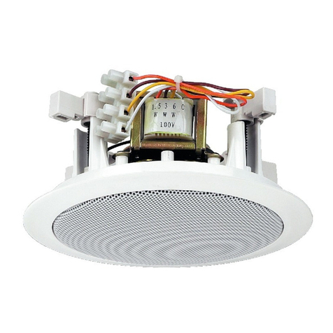
Monacor EDL-165AB-WS User manual

ELECTRONICS FOR SPECIALISTS ELECTRONICS FOR SPECIALISTS ELECTRONICS FOR SPECIALISTS ELECTRONICS FOR SPECIALISTS ELECTRONICS FOR SPECIALISTS ELECTRONICS
EDL-165AB ⁄ WS
Bestellnummer • Order Number 16.3650
MONACOR INTERNATIONAL GmbH & Co. KG • Zum Falsch 36 • 28307 Bremen • Germany
Copyright©by MONACOR INTERNATIONAL. All rights reserved. A-1907.99.01.04.2018
Technische Daten Specifications
Nennbelastbarkeit
100-V-Betrieb
70-V-Betrieb
Power rating
100 V operation
70 V operation
2 × 6 / 3 /1,5W
2 × 3 /1,5 / 0,75W
Frequenzbereich Frequency range 80 – 19 000 Hz
Kennschalldruck SPL 93 dB (1W/1 m)
Max. Nennschalldruck max. SPL 101 dB
Abstrahlwinkel Dispersion angle 180°
Lautsprecher Speaker 13 cm (5”) mit Doppelschwingspule • with dual voice coil
Anschluss Connection Schraubklemmen • screw terminals
Abmessungen Dimensions ⌀170 mm × 95 mm
Einsatztemperatur Ambient temperature −10 …+55 °C
Einbauöffnung Ceiling cutout ⌀140 – 150 mm
Einbautiefe Mounting depth 90 mm
Gewicht Weight 1,1 kg
ELA-Lautsprecher
Diese Anleitung richtet sich an Installateure mit
Fachkenntnissen in der 100-V-Beschallungstech-
nik. Bitte lesen Sie die Anleitung vor der Installation
gründlich durch und heben Sie sie für ein späteres
Nachlesen auf.
1 Verwendungsmöglichkeiten
Der Lautsprecher ist speziell für den Einsatz in ELA-Be-
schallungsanlagen konzipiert und für den Einbau in eine
Leichtbaudecke vorgesehen. Er ist mit einer Zertifizierung
nach EN54-24 für den Einsatz in Sprachalarmierungsan-
lagen zugelassen. Der Lautsprecher ist mit einem ball-
wurfsicheren Ziergitter ausgestattet (nach DIN 18032,
Teil 3). Das geschlossene Metallgehäuse (Feuertopf) er-
schwert im Brandfall eine Ausbreitung des Feuers.
Der Lautsprecher ist mit zwei Übertragern für den
Betrieb in 100-V-Anlagen ausgestattet und besitzt eine
Doppelschwingspule. Er eignet sich daher für ELA-An-
lagen mit A/B-Verkabelung nach EN 60849. Über die
Auswahl der Anschlussklemmen kann zwischen drei
Leistungswerten gewählt werden.
2 Wichtige Hinweise
Der Lautsprecher entspricht allen relevanten Richtlinien
der EU und ist deshalb mit gekennzeichnet.
•
Setzen Sie den Lautsprecher nur im Innenbereich ein
und schützen Sie ihn vor Tropf- und Spritzwasser und
hoher Luftfeuchtigkeit. Der zulässige Einsatztempera-
turbereich beträgt −10 bis +55°C.
•
Verwenden Sie zum Reinigen nur ein trockenes, wei-
ches Tuch, auf keinen Fall Wasser oder Chemikalien.
•
Wird der Lautsprecher zweckentfremdet, nicht richtig
installiert, überlastet oder nicht fachgerecht repariert,
kann keine Haftung für daraus resultierende Sach-
oder Personenschäden und keine Garantie für den
Lautsprecher übernommen werden.
Soll der Lautsprecher endgültig aus dem Be-
trieb genommen werden, übergeben Sie ihn
zur umweltgerechten Entsorgung einem ört-
lichen Recyclingbetrieb.
3 Installation
WARNUNG Im Betrieb liegt berührungsgefährli-
che Spannung bis 100V an der Laut-
sprecherleitung an. Die Installation
darf nur durch Fachpersonal erfolgen.
Achten Sie auf die Belastung des ELA-
Verstärkers durch die Lautsprecher. Eine Überlastung
kann den Verstärker beschädigen!
1) Vor der Installation des Lautsprechers den ELA-
Verstärker ausschalten, damit die Lautsprecherlei-
tung spannungsfrei ist!
2) In die Decke ein Loch mit einem Durchmesser von
140–150mm sägen.
3) Die drei Gehäuseschrauben entfernen und das
Gehäuse öffnen.
4) Die Anschlusskabel für die beiden Lautsprecher-
stromkreise durch die Kabeldurchführungen des
Gehäuses ziehen und jeweils mit einem Klemmen-
block verbinden: Die Klemme mit der weißen Ader
anschließen und die Klemme mit der Ader, die der
gewünschten Nennbelastung (Lautstärke) entspricht
(☞Tabelle). Dabei auf die gleiche Polung aller Laut-
sprecher eines Beschallungsbereichs achten.
Aderfarbe Nennbelastung Impedanz
weiß gemeinsamer Anschluss
gelb 6W 1,7 kΩ
rot 3W 3,3 kΩ
schwarz 1,5W 6,7 kΩ
5) Das Gehäuse wieder schließen.
6) Die drei Klemmfedern nach oben biegen und den
Lautsprecher in die Deckenöffnung einsetzen, sodass
die Federn den Lautsprecher an der Decke festklem-
men.
⚠ 
VORSICHT Verletzungsgefahr
Halten Sie die gespannten Federn gut fest!
Änderungen vorbehalten.
Deutsch
PA Speaker
These instructions are intended for installers with
specific knowledge in sound reproduction using
100V technology. Please read the instructions
carefully prior to installation and keep them for
later reference.
1 Applications
This speaker is specially designed for PA systems and
for installation into lightweight ceilings. With EN 54-24
certification, it has been approved for voice alarm
systems. The speaker is provided with a ball-impact re-
sistant grille (in accordance with DIN18032, Part3). In
case of fire, the closed metal housing (fire dome) will
help to prevent the spread of fire.
The speaker is equipped with two transformers for
operation in 100V systems and with a dual voice coil.
It is therefore suited for PA systems with A/B cabling in
accordance with EN60849. The terminals are used to
define the power (three values are available).
2 Important Notes
The speaker corresponds to all relevant directives of the
EU and is therefore marked with .
•
The speaker is suitable for indoor use only. Protect
it against dripping water, splash water and high air
humidity. The admissible ambient temperature range
is −10 to +55 °C.
•
For cleaning only use a soft, dry cloth; never use water
or chemicals.
3) Remove the three screws and open the housing.
4) Guide the connection cables for the two speaker
circuits through the cable inlets of the housing and
connect each of them to a terminal block: Connect
the terminal with the white core and the terminal
with the core corresponding to the desired power
rating (volume) (☞table). Make sure that all speak-
ers of a speaker zone have the same polarity.
Core colour Power rating Impedance
white common connection
yellow 6W 1.7 kΩ
red 3W 3.3 kΩ
black 1.5W 6.7 kΩ
5) Close the housing.
6) Fold up the three spring clips and insert the speaker
into the ceiling cutout. The spring clips will make
sure that the speaker is held in place on the ceiling.
⚠ 
CAUTION Risk of injury!
When the spring clips are under tension, always hold
them tightly!
Subject to technical modification.
English
•
No guarantee claims for the speaker and no liability
for any resulting personal damage or material dam-
age will be accepted if the speaker is used for other
purposes than originally intended, if it is not correctly
installed, if it is overloaded or if it is not repaired in
an expert way.
If the speaker is to be put out of operation
definitively, take it to a local recycling plant
for a disposal which is not harmful to the
environment.
3 Installation
WARNING During operation, there is a hazard of
contact with a dangerous voltage of up
to 100 V at the speaker cable. Installation
must be made by skilled personnel only.
The total load of the speakers must
not exceed the amplifier power. An overload may
damage the amplifier!
1) Always switch off the PA amplifier before installing
the speaker so that the speaker cable will not carry
any voltage!
2) Saw a cutout (diameter 140–150mm) into the
ceiling.
ELECTRONICS FOR SPECIALISTS ELECTRONICS FOR SPECIALISTS ELECTRONICS FOR SPECIALISTS ELECTRONICS FOR SPECIALISTS ELECTRONICS FOR SPECIALISTS ELECTRONICS
MONACOR INTERNATIONAL GmbH & Co. KG • Zum Falsch 36 • 28307 Bremen • Germany
Copyright©by MONACOR INTERNATIONAL. All rights reserved. A-1907.99.01.04.2018
EDL-165AB ⁄ WS
Référence numérique • Codice 16.3650
Haut-parleur Public Adress
Cette notice s’adresse aux installateurs possédant
des connaissances spécifiques en sonorisation
ligne 100V. Veuillez lire la présente notice avec
attention avant l’installation et conservez-la pour
pouvoir vous y reporter ultérieurement.
1 Possibilités d’utilisation
Ce haut-parleur est spécialement conçu pour une uti-
lisation dans des installations de sonorisation Public
Adress et est prévu pour un montage dans des pla-
fonds légers. Grâce à sa certification EN54-24, il peut
être utilisé dans les installations d’alarme par message.
Il est équipé d’une grille de protection contre les jets de
ballons (selon la norme DIN18 032, partie 3). Le boîtier
métallique clos (capot ignifugé) rend difficile, en cas
d’incendie, une diffusion du feu.
Le haut-parleur est doté de deux transformateurs
pour le fonctionnement avec des installations ligne
100V et possède une double bobine. Il est donc adap-
té pour des installations PA avec câblage A/B selon la
norme EN60849. Trois puissances sont sélectionnables
via les bornes de branchement.
2 Conseils importants
Le haut-parleur répond à toutes les directives nécessaires
de l’Union européenne et porte donc le symbole .
•
Le haut-parleur n’est conçu que pour une utilisation
en intérieur. Protégez-le des éclaboussures, de tout
type de projections d’eau et d’une humidité élevée de
l’air. La plage de température autorisée est de −10°C
à +55°C.
•
Pour le nettoyage, utilisez uniquement un chiffon sec
et doux, en aucun cas de produits chimiques ou d’eau.
•
Nous déclinons toute responsabilité en cas de dom-
mages corporels ou matériels résultants si le haut-
parleur est utilisé dans un but autre que celui pour
lequel il a été conçu, s’il n’est pas correctement ins-
tallé, s’il y a surcharge ou s’il n’est pas réparé par une
personne habilitée ; en outre, la garantie deviendrait
caduque.
Lorsque le haut-parleur est définitivement
retiré du service, vous devez le déposer dans
une usine de recyclage de proximité pour
contribuer à son élimination non polluante.
CARTONS ET EMBALLAGE
PAPIER À TRIER
3 Installation
AVERTISSEMENT Pendant le fonctionnement, une ten-
sion dangereuse jusqu’à 100V est
présente sur le câble haut-parleur.
Seul un personnel qualifié peut effec-
tuer l’installation. Faites attention à
la charge de l’amplificateur PA par les haut-parleurs;
une surcharge peut endommager l’amplificateur.
1) Avant d’installer le haut-parleur, éteignez l’amplifica-
teur Public Adress pour que le câble haut-parleur ne
soit pas porteur de tension.
2) Percez un trou de diamètre 140– 150 mm dans le
plafond.
3) Retirez les trois vis du boîtier et ouvrez le boîtier.
4) Tirez les câbles de branchement pour les deux cir-
cuits haut-parleur via les passages de câble du boîtier
et reliez-les respectivement à un bornier de branche-
ment : reliez la borne avec le conducteur blanc et
reliez la borne avec le conducteur correspondant à
la puissance nominale (volume) souhaitée (☞ ta-
bleau). Veillez à ce que les haut-parleurs de la même
zone de sonorisation aient la même polarité.
Couleur
conducteur
Puissance
nominale Impédance
blanc branchement commun
jaune 6W 1,7 kΩ
rouge 3W 3,3 kΩ
noir 1,5W 6,7 kΩ
5) Refermez le boîtier.
6) Pliez vers le haut les trois ressorts et placez le haut-
parleur dans la découpe pour que les ressorts fixent
le haut-parleur dans le plafond.
⚠ 
ATTENTION Risque de blessure
Tenez fermement les ressorts tendus !
Tout droit de modification réservé.
Français
Altoparlante PA
Queste istruzioni sono rivolte agli installatori con
una conoscenza specifica della riproduzione del
suono utilizzando la tecnologia 100V. Leggere at-
tentamente le istruzioni prima dell’installazione e
conservarle per riferimento futuro
1 Applicazioni
Questo diffusore è stato progettato appositamente per
i sistemi PA e per l’installazione in soffitti leggeri. Con la
certificazione EN54-24, è stato approvato per i sistemi
di allarme vocale. L’altoparlante è dotato di una gri-
glia resistente al lancio di palloni (secondo DIN18032,
parte 3). In caso di incendio, il contenitore metallico
chiuso (cupola antincendio) aiuterà a prevenire la pro-
pagazione del fuoco.
L’altoparlante è dotato di due trasformatori per il fun-
zionamento in sistemi a 100V e con una bobina mobile
doppia. È quindi adatto per sistemi PA con cablaggio A/B
in conformità con EN60849. I terminali sono utilizzati
per definire la potenza (sono disponibili tre valori).
2 Note importanti
L’altoparlante corrisponde a tutte le direttive pertinenti
dell’UE e pertanto è contrassegnato con il marchio .
•
L’altoparlante è adatto solo per uso interno. Pro-
teggerlo dall’acqua, dagli spruzzi e dall’alta umidità
dell’aria. L’intervallo di temperatura ambiente consen-
tito è compreso tra −10 e +55°C.
•
Per la pulizia usare solo un panno morbido e asciutto;
non usare mai acqua o prodotti chimici.
3) Rimuovere le tre viti e aprire il contenitore.
4) Guidare i cavi di collegamento per i due circuiti degli
altoparlanti attraverso gli ingressi dei cavi del con-
tenitore e collegarli a una morsettiera. Collegare il
morsetto con il conduttore bianco e il morsetto con
il conduttore corrispondente alla potenza nominale
desiderata (volume) (☞tabella). Assicurarsi che tutti
gli altoparlanti di una zona degli altoparlanti abbiano
la stessa polarità.
Colore
conduttore Potenza nominale Impedenza
bianco connessione comune
giallo 6W 1,7 kΩ
rosso 3W 3,3 kΩ
nero 1,5W 6,7 kΩ
5) Chiudere il contenitore.
6) Piegare i tre fermagli a molla e inserire l’altoparlante
nell’intaglio del soffitto. Le clip a molla assicureranno
che l’altoparlante sia tenuto in posizione.
⚠ 
ATTENZIONE Pericolo di lesioni!
Quando i fermagli a molla sono in tensione, tenerli
sempre stretti!
Soggetto a modifiche tecniche.
Italiano
•
Nessuna rivendicazione di garanzia e nessuna respon-
sabilità per eventuali danni personali o danni materiali
saranno accettate se l’altoparlante viene utilizzato per
scopi diversi da quelli originariamente previsti, se non
è installato correttamente, se è sovraccarico o se non
è riparato da personale qualificato.
Se l’altoparlante deve essere messo fuori ser-
vizio definitivamente, portarlo in un impianto
di riciclaggio locale per uno smaltimento che
non sia dannoso per l’ambiente.
3 Installazione
AVVERTIMENTO
Durante il funzionamento, c’è il rischio
di contatto con una tensione perico-
losa fino a 100V sul cavo dell’alto-
parlante. L’installazione deve essere
eseguita solo da personale qualificato.
Il carico totale degli altoparlanti non deve superare la
potenza dell’amplificatore. Un sovraccarico può dan-
neggiare l’amplificatore!
1) Spegnere sempre l’amplificatore PA prima di installa-
re l’altoparlante in modo che il cavo dell’altoparlante
non possa portare alcun voltaggio!
2) Applicare un foro (diametro 140– 150mm) nel sof-
fitto.
Caractéristiques
techniques Specifiche
Puissance nominale
Fonctionnement 100 V
Fonctionnement 70 V
Potenza nominale
Funzionamento a 100 V
Funzionamento a 70 V
2 × 6 / 3 /1,5W
2 × 3 /1,5 / 0,75W
Bande passante Gamma di frequenze 80 – 19 000 Hz
Pression sonore SPL 93 dB (1W/1 m)
Pression sonore nominale max. max. SPL 101 dB
Angle diffusion Angolo di dispersione 180°
Haut-parleur Altoparlante 13 cm (5”) avec double bobine • con bobina mobile doppia
Branchement Connessione bornes à vis • morsetti a vite
Dimensions Dimensioni ⌀170 mm × 95 mm
Température fonc. Temperatura ambiente −10 …+55 °C
Découpe Apertura di montaggio ⌀140 – 150 mm
Profondeur montage Profondità di montaggio 90 mm
Poids Peso 1,1 kg

This manual suits for next models

1

Other Monacor Speakers System manuals

Monacor PAB-82WP/WS User manual

Monacor

Monacor PAB-82WP/WS User manual

Monacor ETS-215/WS User manual

Monacor

Monacor ETS-215/WS User manual

Monacor TXA-622CD/SW User manual

Monacor

Monacor TXA-622CD/SW User manual

Monacor ETS-340TW/BN User manual

Monacor

Monacor ETS-340TW/BN User manual

Monacor img Stage Line PROTON-15MK2 User manual

Monacor

Monacor img Stage Line PROTON-15MK2 User manual

Monacor IMG STAGELINE PAK-308M/SW User manual

Monacor

Monacor IMG STAGELINE PAK-308M/SW User manual

Monacor EDL-110/WS User manual

Monacor

Monacor EDL-110/WS User manual

Monacor ESP-315/SW User manual

Monacor

Monacor ESP-315/SW User manual

Monacor SP-1/SW User manual

Monacor

Monacor SP-1/SW User manual

Monacor JTS TG-10R/1 User manual

Monacor

Monacor JTS TG-10R/1 User manual

Monacor ESP-62AB-WS User manual

Monacor

Monacor ESP-62AB-WS User manual

Monacor PA ESP-232/SW User manual

Monacor

Monacor PA ESP-232/SW User manual

Monacor RL-1EN User manual

Monacor

Monacor RL-1EN User manual

Monacor MKA-60SET/SW User manual

Monacor

Monacor MKA-60SET/SW User manual

Monacor PROEL TPR-8A User manual

Monacor

Monacor PROEL TPR-8A User manual

Monacor EDL-412/WS User manual

Monacor

Monacor EDL-412/WS User manual

Monacor TXA-602/SW User manual

Monacor

Monacor TXA-602/SW User manual

Monacor DN-4 User manual

Monacor

Monacor DN-4 User manual

Monacor DN-200 User manual

Monacor

Monacor DN-200 User manual

Monacor SP-2/SW User manual

Monacor

Monacor SP-2/SW User manual

Monacor img Stage Line LR-1000SAT User manual

Monacor

Monacor img Stage Line LR-1000SAT User manual

Monacor EDL-22/WS User manual

Monacor

Monacor EDL-22/WS User manual

Monacor EDL-435/WS User manual

Monacor

Monacor EDL-435/WS User manual

Monacor EDL-170-AL User manual

Monacor

Monacor EDL-170-AL User manual

Popular Speakers System manuals by other brands

Manhattan 3050 instructions

Manhattan

Manhattan 3050 instructions

Electro-Voice EVU-2082/95 user manual

Electro-Voice

Electro-Voice EVU-2082/95 user manual

LG S75QR owner's manual

LG

LG S75QR owner's manual

Pyle PPHP8MBA user manual

Pyle

Pyle PPHP8MBA user manual

LG LAS485B owner's manual

LG

LG LAS485B owner's manual

PSSO CSA Series user manual

PSSO

PSSO CSA Series user manual

Sony HT-ST3 reference guide

Sony

Sony HT-ST3 reference guide

Altec Lansing SLC408 CEILING SPEAKER manual

Altec Lansing

Altec Lansing SLC408 CEILING SPEAKER manual

Definitive Technology Mythos XTR-SSA3 owner's manual

Definitive Technology

Definitive Technology Mythos XTR-SSA3 owner's manual

Pioneer S-1EX operating instructions

Pioneer

Pioneer S-1EX operating instructions

Altec Lansing DTS-640 Specifications

Altec Lansing

Altec Lansing DTS-640 Specifications

Samsung HW-JM4000 user manual

Samsung

Samsung HW-JM4000 user manual

Roberts Blutune 300 user manual

Roberts

Roberts Blutune 300 user manual

Philips HTL4110B quick start guide

Philips

Philips HTL4110B quick start guide

PYLE Audio PPHP127AI user manual

PYLE Audio

PYLE Audio PPHP127AI user manual

Toa F-1000WT Specifications

Toa

Toa F-1000WT Specifications

JVC TH-E851B instruction manual

JVC

JVC TH-E851B instruction manual

EAW CR58 Technical specifications

EAW

EAW CR58 Technical specifications

manuals.online logo
manuals.online logoBrands
  • About & Mission
  • Contact us
  • Privacy Policy
  • Terms and Conditions

Copyright 2025 Manuals.Online. All Rights Reserved.