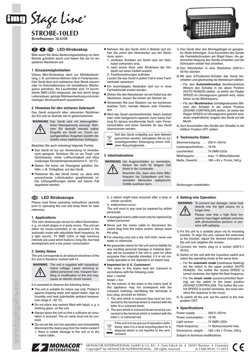
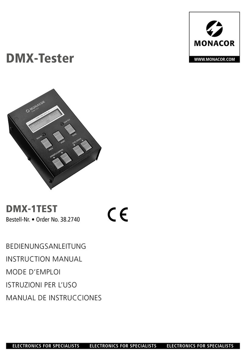
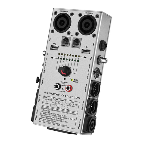
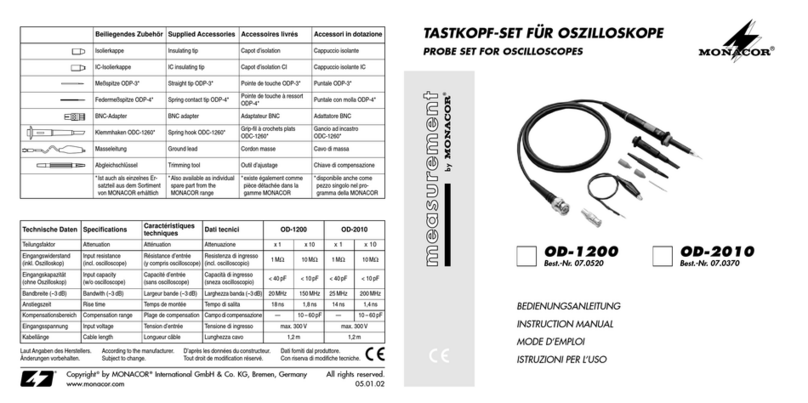
Monacor IMG STAGELINE STROBE-170DMX User manual

DMX-Stroboskop
Bitte lesen Sie diese Bedienungsanleitung vor dem
Betrieb gründlich durch und heben Sie sie für ein
späteres Nachlesen auf.
1 Einsatzmöglichkeiten
Das Hochleistungs-Stroboskop STROBE-170DMX
mit einer 1500-W-Xenon-Blitzlampe ist für den Ein-
satz in professionellen Lichteffektanlagen z.B. auf
Bühnen oder in Diskotheken konzipiert. Die Blitzfre-
quenz und die Blitzhelligkeit lassen sich über ein
Lichtsteuergerät mit DMX512-Protokoll einstellen.
2 Hinweise für den sicheren Gebrauch
Das Gerät entspricht allen erforderlichen Richtlinien
der EU und ist deshalb mit gekennzeichnet.
BeachtenSieauchunbedingtdiefolgendenPunkte:
●Das Gerät ist nur zur Verwendung im Innen-
bereich geeignet. Schützen Sie es vor Tropf- und
Spritzwasser, hoher Luftfeuchtigkeit und Hitze
(zulässiger Einsatztemperaturbereich 0–40°C).
●Zur Vermeidung von Wärmestaus im Gerät muss
die Montagestelle so gewählt werden, dass bei
Betrieb eine ausreichende Luftzirkulation ge-
währleistetist.DieLüftungsöffnungen am Gehäu-
se dürfen nicht abgedeckt werden.
●Halten Sie stets einen Mindestabstand von 1m
zu angestrahlten Objekten und zu leicht ent-
flammbaren oder hitzeempfindlichen Materialien
ein!
●Das Gerät ist nicht für den Dauerbetrieb aus-
gelegt. Längere Betriebsphasen sollten immer
durch Pausen unterbrochen werden.
●NehmenSie dasGerätnichtin Betriebbzw.ziehen
Sie sofort den Netzstecker aus der Steckdose:
1. wennsichtbare Schäden am Gerätoder an der
Netzanschlussleitung vorhanden sind,
2. wenn nach einem Sturz oder Ähnlichem der
Verdacht auf einen Defekt besteht,
3. wenn Funktionsstörungen auftreten.
Lassen Sie Reparaturen nur durch qualifiziertes
Fachpersonal durchführen.
●Eine beschädigte Netzanschlussleitung darf nur
durch qualifiziertes Fachpersonal ersetzt werden.
●Ziehen Sie den Netzstecker nie am Kabel aus der
Steckdose, fassen Sie immer am Stecker an.
●Verwenden Sie zum Reinigen nur ein trockenes
oder leicht angefeuchtetes, weiches Tuch, auf
keinen Fall Chemikalien oder aggressive Reini-
gungsmittel.
●Eine defekte Lampe darf nur von einer qualifizier-
ten Fachkraft durch eine Lampe gleichen Typs er-
setzt werden! Vor dem Lampenwechsel muss un-
bedingt der Netzstecker gezogen und die Lampe
ausreichend abgekühlt sein (min. 5Minuten).
●Wird das Gerät zweckentfremdet, nicht richtig
installiert, falsch bedient oder nicht fachgerecht
repariert, kann keine Haftung für daraus resultie-
rende Sach- oder Personenschäden und keine
Garantie für das Gerät übernommen werden.
Soll das Gerät endgültig aus dem Betrieb
genommenwerden,übergeben Sie es zur
umweltgerechten Entsorgung einem örtli-
chen Recyclingbetrieb.
WARNUNG Das Gerät wird mit lebensgefähr-
licher Netzspannung (230V~) ver-
sorgt. Nehmen Sie deshalb niemals
selbst Eingriffe am Gerät vor und
stecken Sie nichts durch die Lüf-
tungsöffnungen! Es besteht die Ge-
fahr eines elektrischen Schlages.
3 Montage
Das Gerät muss fachgerecht und sicher montiert
werden.
1) Das Gerät über seinen Montagebügel an der
gewünschten Stelle (z.B. Traverse, Leuchten-
stativ) befestigen. Für die Befestigung besitzt der
BügeldreiBohrungen:MitzweiLichtstrahler-Hal-
terungen (C-Haken) oder zwei stabilen Montage-
schrauben das Gerät über die beiden äußeren
Bohrungen des Bügels befestigen. Wird für die
Aufhängung nur eine Halterung bzw. Schraube
verwendet, die mittlere Bohrung des Bügels ver-
wenden.
2) Die zwei Feststellschrauben am Bügel etwas
lösen, den gewünschten Neigungswinkel des
Geräts einstellen und die Schrauben wieder fest
anziehen.
4 Inbetriebnahme
Zum Einschalten des Geräts den Stecker des Netz-
kabels in eine Steckdose (230V~/50Hz) stecken,
die rote Betriebsanzeige „POWER INDICATOR“
leuchtet. ZumAusschalten des Geräts den Netzste-
cker aus der Steckdose ziehen.
Um einen besseren Bedienkomfort zu erhalten,
istesempfehlenswert, das Gerät an eine Steckdose
anzuschließen, die sich über einen Lichtschalter
ein- und ausschalten lässt.
Hinweis: Der Leitungsschutzschalter „CIRCUIT
BREAKER“ unterbricht bei Überstrom automa-
tisch die Stromversorgung (Schalter auf „OFF“).
Lässt sich das Gerät auch nach Zurücksetzen
des Schalters auf „ON“ nicht mehr in Betrieb set-
zen, ist es defekt und muss in einer Fachwerk-
statt repariert werden.
4.1 DMX-Steuerung
Das Stroboskop wird über zwei DMX-Kanäle ge-
steuert (siehe Tabelle, Kap. 5.1). Als DMX-Schnitt-
stelle besitzt das Gerät 3-polige XLR-Anschlüsse
mit folgender Kontaktbelegung:
1 = Masse, 2 = DMX
-
, 3 = DMX+
Zum Anschluss sollten spezielle Kabel für hohen
Datenfluss verwendet werden. Die Verwendung
normaler Mikrofonkabel ist nur bei einer Gesamt-
kabellänge bis 100m zu empfehlen. Die besten
Übertragungsergebnisse werden mit abgeschirm-
ten Mikrofonkabeln von 2 x 0,25mm2oder speziel-
len Datenübertragungskabeln erreicht. Bei Lei-
tungslängen ab 150m wird das Zwischenschalten
eines DMX-Aufholverstärkers empfohlen (z.B. SR-
103DMX von „img Stage Line“).
1) Den Eingang „DMX IN“ mit dem DMX-Ausgang
des Lichtsteuergerätes (z.B. DMX-1440 oder
DMX-60 von „img Stage Line“) verbinden.
2) DenAusgang „DMX OUT“ mit dem DMX-Eingang
des nächsten DMX-gesteuerten Gerätes ver-
binden.DessenAusgang wieder mitdemEingang
WARNUNG 1. Um Augenschäden zu vermei-
den, schauen Sie nie direkt in die
Lichtquelle.
2. Beachten Sie, dass eine hohe
Blitzfrequenz bei fotosensiblen
Menschen und Epileptikern epi-
leptische Anfälle auslösen kann.
3. Betreiben Sie das Gerät nie ohne
die Schutzscheibe.
ACHTUNG: Wird das Gerät nur mit einer Be-
festigung als schwebende Last über Personen
installiert, muss es zusätzlich durch eine zwei-
te, von der ersten unabhängigen Aufhängung
gesichert werden, z.B. durch ein Fangseil. Das
Fangseil so befestigen, dass der Fallweg des
Geräts nicht mehr als 20 cm betragen kann.
des nachfolgenden Gerätes verbinden usw., bis
alle zu steuernden Geräte angeschlossen sind.
Die Ausgangsbuchse besitzt eine Verriege-
lung. Zum Herausziehen des Steckers den
PUSH-Hebel drücken.
3) Den DMX-Ausgang des letzten DMX-gesteuer-
ten Geräts der Kette mit einem 120-Ω-Wider-
stand (> 0,3W) abschließen:An die Pins 2 und 3
eines XLR-Steckers den Widerstand anlöten und
den Stecker in den DMX-Ausgang stecken oder
einen entsprechenden Abschlussstecker (z.B.
DLT-123 von „img Stage Line“) verwenden.
4) Den DIP-Schalter Nr. 10 („TEST“) auf „OFF“ stel-
len und über die DIP-Schalter Nr. 1–9 („AD-
DRESS“) die Startadresse, d.h. die Adresse, die
für die Steuerung des 1. Kanals vorgesehen ist,
als Binärzahl einstellen.
Die Startadresse ergibt sich durch dieAddition
der Stellenwerte der DIP-Schalter, die auf „ON“
gestellt sind, z.B.
Startadresse 1
Schalter Nr. 1 auf „ON“
Startadresse 6 (= 4 + 2)
Schalter Nr. 3 und Nr. 2 auf „ON“
Startadresse 13 (= 8 + 4 + 1)
Schalter Nr. 4, Nr. 3 und Nr. 1 auf „ON“
Immer vom größtmöglichen Stellenwert ausge-
hen und die kleineren Werte absteigend dazu-
addieren.
Der 2. Kanal ist automatisch der Adresse zuge-
ordnet, die auf die Startadresse folgt (z.B Start-
adresse 13 für Kanal 1, Adresse 14 für Kanal 2).
5) Das Stroboskop kann jetzt anhand der Tabelle in
Kap. 5.1 gesteuert werden. Die grüne LED „DMX
INDICATOR“signalisiert den Empfang von DMX-
Steuersignalen.
4.2 Testbetrieb
Um die Funktionsfähigkeit des Stroboskops zu tes-
ten, den DIP-Schalter Nr. 10 („TEST“) auf „ON“ stel-
len: Ein Testprogramm läuft ab. DMX-Steuersignale
werden dabei ignoriert (grüne LED „DMX INDICA-
TOR“ aus).
5 Technische Daten
Stromversorgung: . 230V~/50 Hz/1750W max.
Leuchtmittel: . . . . . 1500-W-Xenon-Blitzlampe
Blitzfrequenz: . . . . . max. 12 Blitze/s
Maße, Gewicht: . . . 46 x 22x 13cm, 4,8kg
5.1 Belegung der DMX-Kanäle
Änderungen vorbehalten.
256
1
2
4
8
16
32
64
128
10987654321
OND
I
P
TEST
256
1
2
4
8
16
32
64
128
10987654321
OND
I
P
TEST
256
1
2
4
8
16
32
64
128
10987654321
OND
I
P
TEST
wwwwww..iimmggssttaaggeelliinnee..ccoomm
STROBE-170DMX
Best.-Nr. 38.2730
Copyright©by MONACOR INTERNATIONAL GmbH & Co. KG, Bremen, Germany. All rights reserved. A-0660.99.01.09.2006
®
D A CH
Kanal 1: Blitzfrequenz
0 →255 min. Frequenz →max. Frequenz
10 →255 min. Helligkeit →max. Helligkeit
0–9 Lampe aus
Kanal 2: Blitzhelligkeit
DMX-Wert Funktion
Stellenwerte

DMX Stroboscope
Please read these operating instructions carefully
priorto operatingtheunit andkeepthem forlateruse.
1 Applications
The high power stroboscope STROBE-170DMX
with a 1500W Xenon strobe lamp has been de-
signed for use in professional light effect systems,
e.g. on stage or in discothèques. The flash rate and
the flash brightness can be adjusted via a light con-
troller with DMX512 protocol.
2 Safety Notes
The unit corresponds to all required directives of the
EU and is therefore marked with .
It is essential to observe the following items:
●The unit is suitable for indoor use only. Protect it
against dripping water and splash water, high air
humidity, and heat (admissible ambient tempera-
ture range 0–40°C).
●To prevent a heat accumulation within the unit,
the place of mounting must be selected so that a
sufficient air circulation will be ensured during
operation. The vents at the housing must not be
covered.
●Always keep a minimum distance of 1m to illu-
minated objects and material which is easily
inflammable or sensitive to heat!
●The unit is not suitable for permanent operation.
Longer operating phases should always be inter-
rupted by breaks.
●Do not set the unit into operation, or immediately
disconnect the mains plug from the mains socket if
1. there is visible damage to the unit or to the
mains cable,
2. a defect might have occurred after a drop or
similar accident,
3. malfunctions occur.
The unit must in any case be repaired by skilled
personnel.
●Adamagedmains cable must only be replaced by
authorized, skilled personnel.
●Never pull the mains cable to disconnect the
mains plug from the mains socket, always seize
the plug.
●For cleaning only use a soft cloth, dry or slightly
wet, by no means chemicals or aggressive deter-
gents.
●Adefective lamp must only be replaced by a lamp
of the same type by qualified personnel! Prior to
replacing the lamp, always disconnect the mains
plug and let the lamp sufficiently cool down (for
5 minutes as a minimum).
●Noguaranteeclaimsfortheunitandnoliabilityfor
any resulting personal damage or material
damage will be accepted if the unit is used for
other purposes than originally intended, if it is not
correctly installed, operated, or not repaired in an
expert way.
●Important for U.K. Customers!
The wires in this mains lead are coloured in ac-
cordance with the following code:
green/yellow = earth, blue = neutral, brown = live.
As the colours of the wires in the mains lead of
this appliance may not correspond with the col-
oured markings identifying the terminals in your
plug, proceed as follows:
1. The wire which is coloured green and yellow
must be connected to the terminal in the plug
WARNING The unit is supplied with hazardous
mains voltage (230V~). Leave ser-
vicing to skilled personnel only.
Never insert anything through the
vents! Inexpert handling of the unit
maycauseanelectric shock hazard.
whichismarkedwith the letter E or by the earth
symbol ,or coloured green or green and yel-
low.
2. The wire which is coloured blue must be con-
nected to the terminal which is marked with the
letter N or coloured black.
3. The wire which is coloured brown must be con-
nected to the terminal which is marked with the
letter L or coloured red.
WARNING – This appliance must be earthed.
3 Mounting
The unit must be mounted in a safe and expert way.
1) Fixtheunitvia its mounting bracket at the desired
location (e.g. traverse or lighting stand). For
fixing, the bracket is provided with three drilled
holes: With two supports for projectors (C hooks)
or two stable mounting screws fix the unit via the
two outer drilled holes of the bracket. If only one
support or screw is used for the suspension, use
the central drilled hole of the mounting bracket.
2) Slightly release the two setscrews at the bracket,
adjust the desired angle of inclination of the unit,
and retighten the screws.
4 Setting into Operation
To switch on the unit, connect the plug of the mains
cable to a socket (230V~/50Hz), the red power
LED “POWER INDICATOR” lights up. To switch off
the unit, disconnect the mains plug from the socket.
For a more convenient operation it is recom-
mended to connect the unit to a mains socket which
can be switched on and off via a light switch.
Note: The “CIRCUIT BREAKER” switch automati-
cally interrupts the power supply in case of over-
current (switch in “OFF” position). If the unit can-
notbeset into operation even after the switchhas
been reset to “ON”, it is defective and must be
repaired in a special workshop.
4.1 DMX control
The stroboscope is controlled via two DMX chan-
nels (see table, chapter 5.1). As a DMX interface,
the unit has 3-pole XLR connectors with the fol-
lowing pin configuration:
1 = ground, 2 = DMX
-
, 3 = DMX+
For connection, special cables for high data flow
should be used. The use of standard microphone
cables can only be recommended for a total cable
length of up to 100m. The best transmission results
are obtained with screened microphone cables of
2 x 0.25m2or special data transmission cables. For
cable lengths exceeding 150m it is recommended
to insert a DMX level matching amplifier (e.g. SR-
103DMX from “img Stage Line).
WARNING 1. To prevent eye damage, never
look directly into the light source.
2. A high flash frequency may trig-
ger epileptic seizures with photo-
sensitive persons and persons
with epilepsy!
3. Never operate the unit without
protective pane.
ATTENTION: If the unit is mounted as a sus-
pendedloadabove persons with only onefixing
device, it must additionally be secured by a
secondsuspensionwhichisindependentofthe
first, e.g. by a safety rope. Fix the safety rope
so that the maximum falling distance of the unit
does not exceed 20cm.
If the unit is to be put out of operation de-
finitively, take it to a local recycling plant
for a disposal which is not harmful to the
environment.
1) Connect the input “DMX IN” to the DMX output of
the light controller (e.g. DMX-1440 or DMX-60
from “img Stage Line”).
2) Connect the output “DMX OUT” to the DMX input
ofthe nextunitcontrolledbyDMX.Connectits out-
putagain to the inputof the following unit,etc. until
all units to be controlled have been connected.
The output jack has a latching. To remove the
plug, press the PUSH lever.
3) Terminate the DMX output of the last unit con-
trolled by DMX in the row with a 120Ωresistor
(>0.3W): Solder the resistor to the pins 2 and 3
of an XLR plug and connect the plug to the DMX
output or use a corresponding terminating plug
(e.g. DLT-123 from “img Stage Line”).
4) Set the DIP switch No. 10 (“TEST”) to “OFF” and
adjustthestartaddress, i.e. the address provided
for control of the first channel, as a binary number
with the DIP switches Nos. 1–9 (“ADDRESS”).
The start address will result from adding the
place values of the DIP switches set to “ON”, e.g.
start address 1
switch No. 1 set to “ON”
start address 6 (= 4 + 2)
switches No. 3 and No. 2 set to “ON”
start address 13 (= 8 + 4 + 1)
switches No. 4, No. 3,
and No. 1 set to “ON”
Always start from the highest possible place
value and add the lower values in descending
order.
The second channel is automatically assigned to
theaddress following the start address (e.g. start
address 13 for channel 1, address 14 for chan-
nel 2).
5) The stroboscope can now be controlled by
means of the table in chapter 5.1.The green LED
“DMX INDICATOR” signalizes the reception of
DMX control signals.
4.2 Test operation
To test the correct functioning of the stroboscope,
set the DIP switch No. 10 (“TEST”) to “ON”: A test
programme is running. Then DMX control signals
are ignored (green LED “DMX INDICATOR” off).
5 Specifications
Power supply: . . . . 230V~/50Hz/1750W max.
Lamp: . . . . . . . . . . . 1500W Xenon flash lamp
Flash rate: . . . . . . . max. 12 flashes/s
Dimensions, weight: 46 x 22 x 13cm, 4.8kg
5.1 Configuration of the DMX channels
Subject to modification.
256
1
2
4
8
16
32
64
128
10987654321
OND
I
P
TEST
256
1
2
4
8
16
32
64
128
10987654321
OND
I
P
TEST
256
1
2
4
8
16
32
64
128
10987654321
OND
I
P
TEST
wwwwww..iimmggssttaaggeelliinnee..ccoomm
STROBE-170DMX
Order No. 38.2730
Copyright©by MONACOR INTERNATIONAL GmbH & Co. KG, Bremen, Germany. All rights reserved. A-0660.99.01.09.2006
®
GB
channel 2: flash brightness
channel 1: flash rate
DMX value Function
0 →255 min. rate →max. rate
10 →255 min. brightness →max. brightness
0–9 lamp off
place values

Stroboscope DMX
Veuillez lire la présente notice avec attention avant
le fonctionnement et conservez-la pour pouvoir
vous y reporter ultérieurement.
1 Possibilités d’utilisation
Le stroboscope de grande puissance STROBE-
170DMXéquipé d’unelampeàéclairsxénon1500W
est conçu pour une utilisation dans des installations
professionnelles de jeux de lumière, par exemple
sur scène et en discothèque. La fréquence et la
luminosité des éclairs se règlent via un contrôleur
DMX avec protocole DMX512.
2 Conseils d’utilisation et de sécurité
L’appareil répond à toutes les directives nécessaires
de l’Union Européenne et porte donc le symbole .
Respectez scrupuleusement les points suivants :
●L’appareil n’est conçu que pour une utilisation en
intérieur. Protégez-le de tout type de projections
d’eau, des éclaboussures, d’une humidité élevée
d’air et de la chaleur (plage de température de
fonctionnement autorisée : 0–40°C).
●Pour éviter toute accumulation de chaleur dans
l’appareil,lelieudemontagedoitêtre choisidetelle
sortequ’une circulationd’airsuffisantesoitassurée
pendantle fonctionnement.Enaucun caslesouïes
de ventilation du boîtier ne doivent être obturées.
●Conservez toujours une distance minimale de
1m avec les objets éclairés, avec les matériaux
facilement inflammables ou sensibles à la chaleur !
●L’appareiln’estpasconçu pour un fonctionnement
en continu. Il est recommandé de couper toujours
les longues périodes d’utilisation par des pauses.
●Ne faites pas fonctionner l’appareil ou débran-
chez-le immédiatement du secteur lorsque :
1. des dommages apparaissent sur l’appareil ou
sur le cordon secteur,
2. après une chute ou un cas similaire, vous avez
un doute sur l’état de l’appareil,
3. des dysfonctionnement apparaissent.
Dans tous les cas, les dommages doivent être
réparés par un technicien spécialisé.
●Tout cordon secteur endommagé doit être rem-
placé uniquement par un technicien habilité.
●Ne débranchez jamais l’appareil en tirant sur le
cordonsecteur ; retirez toujoursle cordon secteur
en tirant la fiche.
●Pour le nettoyage, utilisez seulement un chiffon
secoulégèrement humide et doux, en aucun cas,
de produits chimiques ou de détergents abrasifs.
●Seul un personnel qualifié peut remplacer une
lampe défectueuse par une lampe de même type !
Avantde remplacer la lampe, débranchezimpéra-
tivementla fiche du secteuret laissez refroidir suf-
fisamment la lampe (5 minutes au mois).
●Nous déclinons toute responsabilité en cas de
dommages matériels ou corporels résultants si
l’appareil est utilisé dans un but autre que celui
pour lequel il a été conçu, s’il n’est pas correcte-
ment installé, utilisé ou n’est pas réparé par une
personne habilitée, en outre, la garantie devien-
drait caduque.
Lorsque l’appareil est définitivement retiré
du service, vous devez le déposer dans
uneusine de recyclage adaptée pourcon-
tribuer à son élimination non polluante.
AVERTISSEMENT L’appareil est alimenté par
une tension dangereuse
230V~. Ne touchez jamais
l’intérieur de l’appareil et ne
faites rien tomber dans les
ouïes de ventilation ! Risque
de décharge électrique.
3 Montage
L’appareil doit être monté de manière profes-
sionnelle et sûre.
1) Fixez l’appareil via son étrier de montage à l’en-
droit souhaité (p.ex. traverse, pied de lumière).
Pour la fixation, l’étrier possède trois trous : fixez
l’appareil via les deux trous extérieurs de l’étrier
avecdeuxsupportsde projecteur (crochets en C)
ou deux vis de montage solides. Utilisez le trou
du milieu sur l’étrier si un seul support ou une
seule vis est utilisée pour le suspendre.
2) Desserrez un peu les deux vis de réglage sur
l’étrier, réglez l’angle d’inclinaison souhaité de
l’appareil puis revissez les vis.
4 Fonctionnement
Pour allumer l’appareil, reliez la fiche du cordon sec-
teur à une prise secteur (230V~/50Hz), le témoin
rouge de fonctionnement “POWER INDICATOR”
brille. Pour éteindre l’appareil, débranchez le cor-
don secteur.
Pour un meilleur confort d’utilisation, il est
recommandé de relier l’appareil à une prise secteur
pouvant être allumée et éteinte via un interrupteur.
Conseil : L’interrupteur “CIRCUIT BREAKER” inter-
rompt automatiquement l’alimentation en cas de
courant de surcharge (interrupteur sur “OFF”). Si
l’appareil ne se remet pas en fonction même si
l’interrupteur est remis sur “ON”, il est défectueux
et doit être réparé par un atelier habilité.
4.1 Gestion DMX
Le stroboscope est géré via deux canaux DMX (voir
tableau chapitre 5.1). L’appareil dispose de con-
nexions XLR 3 pôles avec la configuration suivante
comme interface DMX :
1 = masse, 2 = DMX
-
, 3 = DMX +
Pour le branchement, il est recommandé d’utiliser
des câbles spécifiques pour des flots importants de
données. L’emploi de câbles micro usuels ne peut
être recommandé que pour des longueurs de câble
de 100m maximum. Les meilleurs résultats de
transmission sont obtenus avec des câbles micro
blindés de section 2 x 0,25mm2ou avec des câbles
spécifiques pour la transmission de données. Pour
des longueurs de liaison à partir de 150m, il est
recommandé d’insérer un amplificateur DMX de
signal (par exemple SR-103DMX de “img Stage
Line”).
1) Reliez l’entrée “DMX IN” à la sortie DMX du con-
trôleur (par exemple DMX-1440 ou DMX-60 de
“img Stage Line”).
2) Reliez la sortie “DMX OUT” à l’entrée DMX de
l’appareil suivant géré par DMX. Reliez sa sortie
AVERTISSEMENT 1. Ne regardez jamais direc-
tement la source de
lumière pour éviter tout
dommage sur les yeux.
2. Gardez présent à l’esprit
qu’une fréquence élevée
des éclairs peut causer
des attaques d’épilepsie
sur les personnes photo-
sensibles ou épileptiques.
3. Ne faites jamais fonc-
tionner l’appareil sans la
vitre de protection.
ATTENTION : Si l’appareil doit être installé
comme charge suspendue au-dessus de per-
sonnes avec une seule fixation, il doit être en
plusassuréparunesecondesuspension,indé-
pendante de la première, par exemple avec
une corde de sécurité. Fixez la corde de telle
sorte que la distance de chute de l’appareil ne
puisse pas être supérieure à 20cm.
à l’entrée du prochain appareil et ainsi de suite
jusqu’àcequetousappareilsàgérersoient reliés.
La prise de sortie DMX possède un verrouil-
lage.Pour retirer la fiche,enfoncezlelevier PUSH.
3) Terminez la sortie DMX du dernier appareil géré
par DMX de la chaîne avec une résistance 120Ω
(>0,3W) : soudez aux pins2 et 3 d’une fiche XLR
la résistance et branchez la fiche dans la sortie
DMX ou utilisez un bouchon correspondant (par
exemple DLT-123 de “img Stage Line”).
4) Mettez l’interrupteur DIP numéro 10 (“TEST”) sur
“OFF”etréglezvialesinterrupteursDIPnuméros
1 à 9 (“ADDRESS”) sous forme de valeur binaire
l’adresse de démarrage, c’est-à-dire l’adresse
prévue pour la gestion du canal 1.
L’adresse de démarrage s’obtient en addi-
tionnant les valeurs des interrupteurs DIP, mis
sur “ON”, par exemple :
Adresse de démarrage 1
Interrupteur no. 1 sur “ON”
Adresse de démarrage 6 (= 4 + 2)
Interrupteurs no. 3 et no. 2 sur “ON”
Adresse de démarrage 13 (= 8 + 4 + 1)
Interrupteurs no. 4, no. 3 et no. 1
sur “ON”
Partez toujours de la valeur de réglage la plus
grande possible et ajoutez, en ordre décroissant,
les valeurs plus petites.
Le canal 2 est automatiquement attribué à
l’adresse suivant l’adresse de démarrage (par
exemple adresse de démarrage 13 pour le
canal 1, adresse 14 pour le canal 2).
5) En fonction des indications du tableau du cha-
pitre 5.1, on peut gérer le stroboscope. La LED
verte “DMX INDICATOR” signale la réception
des signaux de commande DMX.
4.2 Mode test
Pour tester le fonctionnement du stroboscope, met-
tez l’interrupteur DIP numéro 10 (“TEST”) sur “ON” :
un programme de test se lance. Les signaux de
commande DMX sont ignorés (la LED verte “DMX
INDICATOR” est éteinte).
5 Caractéristiques techniques
Alimentation : . . . . . . . 230V~/50Hz/
1750W max.
Lampe : . . . . . . . . . . . lampe à éclairs au xénon
1500W
Fréquence des éclairs : 12 éclairs/smax.
Dimensions, poids : . . 46 x 22 x 13cm, 4,8kg
5.1 Configuration des canaux DMX
Tout droit de modification réservé.
256
1
2
4
8
16
32
64
128
10987654321
OND
I
P
TEST
256
1
2
4
8
16
32
64
128
10987654321
OND
I
P
TEST
256
1
2
4
8
16
32
64
128
10987654321
OND
I
P
TEST
wwwwww..iimmggssttaaggeelliinnee..ccoomm
STROBE-170DMX
Ref. num. 38.2730
Copyright©by MONACOR INTERNATIONAL GmbH & Co. KG, Bremen, Germany. All rights reserved. A-0660.99.01.09.2006
®
F B CH
Canal 2: luminosité des éclairs
Canal 1: fréquence des éclairs
Valeur DMX Fonction
0 →255 fréquence min. →fréquence max.
10 →255 luminosité min. →luminosité max.
0–9 lampe éteinte
Valeurs de réglage

Stroboscopio DMX
Vi preghiamo di leggere attentamente le presenti
istruzioni prima della messa in funzione e di con-
servarle per un uso futuro.
1 Possibilità d’impiego
Lo stroboscopio di potenza STROBE-170DMX con
il suo lampeggiante di 1500W allo Xenon è stato
realizzato per l’impiego in impianti professionali di
effetti di luce, p.es. in teatro o discoteca. La fre-
quenza dei lampi e la loro luminosità possono
essere regolate per mezzo di un’unità di comando
luce con protocollo DMX512.
2 Avvertenze di sicurezza
L’apparecchio è conforme a tutte le direttive richie-
ste dell’UE e pertanto porta la sigla .
Si devono osservare assolutamente anche i
seguenti punti:
●Lo strumento è previsto solo per l’uso all’interno
di locali. Proteggerlo dall’acqua gocciolante e
dagli spruzzi d’acqua, da alta umidità dell’aria e
dal calore (temperatura d’impiego ammessa fra
0 e 40°C).
●Perevitare unaccumulodicalorenell’apparecchio,
il luogo di montaggio deve essere scelto in modo
tale che sia garantita una ventilazione sufficiente
durante il funzionamento. Le aperture di aerazione
del contenitore non devono essere coperte.
●Tenere una distanza minima di 1m da oggetti
irradiati e da materiali facilmente infiammabili o
sensibili al calore!
●L’apparecchio non è previsto per un impiego per-
manente. Le fasi prolungate di funzionamento
dovrebbero sempre essere interrotte da pause.
●Non mettere in funzione l’apparecchio e staccare
subito la spina rete se:
1. l’apparecchio o il cavo rete presentano dei
danni visibili;
2. dopo una caduta o dopo eventi simili sussiste
il sospetto di un difetto;
3. l’apparecchio non funziona correttamente.
Per la riparazione rivolgersi sempre ad un’officina
competente.
●Il cavo rete, se danneggiato, deve essere sosti-
tuito solo da personale qualificato.
●Staccare il cavo rete afferrando la spina, senza
tirare il cavo.
●Per la pulizia usare solo un panno morbido, asciut-
to o leggermente inumidito; non impiegare in nes-
sun caso prodotti chimici o detergenti aggressivi.
●Una lampadina difettosa deve essere sostituita
solo da una persona qualificata e con una lampa-
dina dello stesso tipo! Prima della sostituzione
della lampadina occorre assolutamente staccare
la spina di rete e la lampadina deve essersi raf-
freddata sufficientemente (min. 5 minuti).
●Nel caso d’uso improprio, d’installazione sba-
gliata, d’impiego scorretto o di riparazione non a
regola d’arte dell’apparecchio, non si assume
nessuna responsabilità per eventuali danni con-
sequenziali a persone o a cose e non si assume
nessuna garanzia per l’apparecchio.
Se si desidera eliminare l’apparecchio
definitivamente, consegnarlo per lo smal-
timento ad un’istituzione locale per il
riciclaggio.
AVVERTIMENTO L’apparecchio funziona con
pericolosa tensione di rete
(230V~). Non intervenire mai
al suo interno e non inserire
niente nelle fessure di aera-
zione! Esiste il pericolo di una
scarica elettrica.
3 Montaggio
L’apparecchio deve essere montato a regola d’arte
e in modo sicuro.
1) Fissare l’apparecchio, per mezzo della sua staffa
di montaggio, al posto desiderato (p.es. tra-
versa, stativo per lampade). Per il fissaggio, la
staffa dispone di tre fori: fissare l’apparecchio ai
due fori esterni della staffa usando due supporti
per spot (ganci a C) o due viti robuste di mon-
taggio. Se per la sospensione si usa un solo sup-
porto o una sola vite, utilizzare il foro centrale
della staffa.
2) Allentare leggermente le due viti di bloccaggio
sulla staffa, impostare l’inclinazione dell’appa-
recchio e stringere di nuovo le viti.
4 Messa in funzione
Per accendere l’apparecchio, inserire la spina del
cavo rete in una presa di rete (230V~/50Hz); si
accende la spia rossa di funzionamento “POWER
INDICATOR”. Per spegnere l’apparecchio, staccare
la spina dalla presa.
Per maggiore comodità conviene collegare l’ap-
parecchio con una presa comandata da un interrut-
tore di luce.
N.B.: L’interruttore magnetotermico “CIRCUIT
BREAKER” interrompe l’alimentazione automati-
camente in caso di sovracorrente (interruttore su
“OFF”). Se l’apparecchio non funziona più nean-
che dopo aver messo l’interruttore su “ON”,
richiede una riparazione in un laboratorio specia-
lizzato.
4.1 Comando DMX
Lo stroboscopio è comandato tramite due canali
DMX (vedi tabella, cap. 5.1). Come interfaccia
DMX, l’apparecchio dispone di contatti XLR a 3 poli.
I contatti sono i seguenti:
1 = massa, 2 = DMX
-
, 3 = DMX+
Per il collegamento si dovrebbero usare cavi spe-
ciali per un alto flusso di dati. L’impiego di normali
cavi per microfoni è consigliabile solo per una
lunghezza complessiva dei cavi fino a 100m. I mi-
gliori risultati di trasmissione si ottengono con cavi
schermati per microfoni di 2 x 0,25mm2oppure con
cavi speciali per la trasmissione dati. Nel caso di
lunghezze oltre i 150 m è consigliabile l’inserimento
di un amplificatore DMX (p.es. SR-103DMX “img
Stage Line”).
1) Collegare l’ingresso “DMX IN” con l’uscita DMX
dell’unità di comando luce (p.es. DMX-1440 o
DMX-60 di “img Stage Line”).
2) Collegare l’uscita “DMX OUT” con l’ingresso
DMX della successiva unità comandata da DMX.
L’uscita di quest’ultima con l’ingresso dell’unità
successiva e via dicendo finché tutte le unità da
comandare sono collegate.
AVVERTIMENTO 1. Per escludere danni agli
occhi, non guardare mai di-
rettamente nella fonte di
luce.
2. Da notare che un’alta fre-
quenza dei lampi può pro-
vocare, in persone sensibili
alla luce e epilettici, degli
attacchi di epilessia.
3. Mai usare l’apparecchio
senza il vetro protettivo.
ATTENZIONE: Se l’apparecchio viene instal-
lato con un solo fissaggio e in modo sospeso
sopra delle persone, deve essere assicurato
da una seconda sospensione indipendente
dallaprima, p. es. permezzo di una fune ditrat-
tenuta. Fissare la fune in modo tale che la
caduta dell’unità non possa superare i 20cm.
La presa d’uscita è provvista di un bloccaggio.
Per staccare la spina, premere la levetta PUSH.
3) Terminare con una resistenza di 120Ω(>0,3W)
l’uscita DMX dell’ultima unità comandata da
DMX: saldare la resistenza ai pin 2 e 3 di un con-
nettore XLR e inserire il connettore nell’uscita
DMX oppure usare un connettore terminatore
adatto (p.es. DLT-123 di “img Stage Line”).
4) Portare il DIP-switch n. 10 (“TEST”) su “OFF” e
con i DIP-switch n. 1– 9 (“ADDRESS”) impostare
come numero binario l’indirizzo di start, cioè l’in-
dirizzo previsto per il comando del 1. canale.
L’indirizzo di start risulta dall’addizione dei
valori della postazione dei DIP-switch messi su
“ON”, p.es.
Indirizzo di start 1
Switch n. 1 su “ON”
Indirizzo di start 6 (= 4 + 2)
Switch n. 3 e n. 2 su “ON”
Indirizzo di start 13 (= 8 + 4 + 1)
Switch n. 4, n. 3 e n. 1 su “ON”
Partire sempre dal valore maggiore e aggiun-
gere, in modo decrescente, i valori minori.
Al 2. canale viene assegnato automaticamente
l’indirizzoche segue l’indirizzo di start(p.es. indi-
rizzo di start 13 per il canale 1, indirizzo 14 per il
canale 2).
5) A questo punto, lo stroboscopio può essere
comandato secondo la tabella in cap. 5.1. Il LED
verde “DMX INDICATOR” segnala la ricezione di
segnali di comando DMX.
4.2 Modalità di test
Per testare la funzionalità dello stroboscopio, por-
tare il DIP-switch n. 10 (“TEST”) su “ON”: si svolge
un programma di test. In questo caso, i segnali di
comando DMX sono ignorati (LED verde “DMX
INDICATOR” spento).
5 Dati tecnici
Alimentazione: . . . . 230V~/50Hz/1750W max.
Lampadina: . . . . . . lampeggiante di 1500W allo
Xenon
Frequenza lampi: . . max. 12 lampi/s
Dimensioni, peso: . 46 x 22 x 13cm, 4,8kg
5.1 Assegnazione dei canali DMX
Con riserva di modifiche tecniche.
256
1
2
4
8
16
32
64
128
10987654321
OND
I
P
TEST
256
1
2
4
8
16
32
64
128
10987654321
OND
I
P
TEST
256
1
2
4
8
16
32
64
128
10987654321
OND
I
P
TEST
wwwwww..iimmggssttaaggeelliinnee..ccoomm
STROBE-170DMX
N. articolo 38.2730
Copyright©by MONACOR INTERNATIONAL GmbH & Co. KG, Bremen, Germany. All rights reserved. A-0660.99.01.09.2006
®
I
Canale 2: luminosità del lampo
Canale 1: frequenza dei lampi
Valore DMX Funzione
0 →255 frequenza min. →frequenza max.
10 →255 luminosità min. →luminosità max.
0–9 lampada spenta
Valori della postazione

Estroboscopio DMX
Por favor, lea estas instrucciones de uso atenta-
mente antes de utilizar la unidad y guárdelas para
usos posteriores.
1 Aplicaciones
Elestroboscopio dealtapotenciaSTROBE-170DMX
con una lámpara estroboscópica de Xenón de
1500W ha sido diseñado para el uso en sistemas
de efecto de luz profesionales, p.ej. en escenario o
en discotecas. El índice de flash y el brillo de flash
se pueden ajustar mediante un controlador de luz
con protocolo DMX512.
2 Notas de seguridad
La unidad corresponde a todas las Directivas re-
queridas por la UE y por ello está marcada con .
Es esencial tener en cuenta los puntos siguientes:
●La unidad sólo está indicada para el uso en inte-
rior. Protéjala de goteos y salpicaduras de agua,
dela humedad elevada del aire, ydelcalor (gama
de temperatura ambiente admisible 0–40°C).
●Para prevenir una acumulación de calor dentro
de la unidad, la posición de montaje debe selec-
cionarse de manera que se asegure una circula-
ción de aire suficiente durante el funcionamiento.
No se deben cubrir las aberturas de ventilación
en la carcasa.
●Mantengasiempre una distancia mínima de 1 m
con los objetos iluminados y con materiales fácil-
mente inflamables o sensibles al calor!
●La unidad no está indicada para el funcio-
namiento permanente. Las fases de funcio-
namiento más largas se deberían interrumpir
siempre con pausas.
●No ponga la unidad en funcionamiento, o des-
conecte inmediatamente el enchufe de la toma
de red si
1. existe un daño visible en la unidad o en el
cable de red,
2. ha ocurrido un defecto tras una caída o un
accidente similar,
3. ocurre un mal funcionamiento.
En cualquier caso la unidad debe ser reparada
por personal especializado.
●Un cable de red dañado sólo debe ser rempla-
zado por personal autorizado.
●No tire nunca del cable de red para desconectar
el enchufe de la toma de red, tire siempre del
enchufe.
●Para limpiar use sólo un paño suave, seco o lige-
ramente húmedo, no utilice productos químicos o
detergentes agresivos.
●¡Una lámpara defectuosa sólo debe ser rempla-
zada por una lámpara del mismo tipo por perso-
nalespecializado!Antes de remplazar lalámpara,
desconectesiempre el enchufe y deje enfriarsufi-
cientemente la lámpara (durante 5 minutos como
mínimo).
●No se aceptará ninguna garantía para la unidad
ni se asumirá ninguna responsabilidad en caso
de daños personales o patrimoniales resultantes
si se usa la unidad para otros fines distintos a los
originalmente concebidos, si no se instala o se
utiliza correctamente, o si no se repara de
manera experta.
ADVERTENCIA La unidad se alimenta con un
voltajederedpeligroso(230V~).
Deje el mantenimiento sólo en
manos de personal especia-
lizado. ¡No introduzca nada en
las aberturas de ventilación!
Una manipulación inexperta de
la unidad puede provocar un
riesgo de shock eléctrico.
3 Montaje
Se debe montar la unidad de manera segura y
experta.
1) Fijela unidad mediante su soporte demontaje en
el lugar deseado (p.ej. una viga transversal o un
soporte para luces). Para la fijación, el soporte
está provisto con tres perforaciones: Con dos
soportes para proyectores (ganchos de seguri-
dad) o dos tornillos de montaje estables, fije la
unidad mediante las dos perforaciones exterio-
res del soporte. Si sólo se usa un soporte o
tornillo para la suspensión, use la perforación
central del soporte de montaje.
2) Suelte ligeramente los dos tornillos de ajuste enel
soporte, ajuste el ángulo de inclinación deseado
de la unidad, y vuelva a apretar los tornillos.
4 Puesta en marcha
Para encender la unidad, conecte el enchufe del
cable de red a una toma (230V~/50Hz), el LED de
funcionamiento rojo “POWER INDICATOR” se en-
ciende. Para apagar la unidad, desconecte el
enchufe de la toma.
Para un funcionamiento más cómodo se reco-
mienda conectar la unidad a una toma de red que
se pueda encender y apagar mediante un inter-
ruptor de encendido.
Nota: El interruptor “CIRCUIT BREAKER” inter-
rumpe automáticamente la alimentación en caso
de exceso de corriente (interruptor en posición
“OFF”).Sino se puede poner enmarchalaunidad
incluso tras haberla reajustado en “ON”, es defec-
tuosa y debe repararse en un taller especial.
4.1 Control DMX
El estroboscopio está controlado mediante dos
canales DMX (vea la tabla, capítulo 5.1). Como una
interfaz DMX, la unidad tiene conectores XLR de
3 polos con la configuración pin siguiente:
1 = masa, 2 = DMX
-
, 3 = DMX+
Para la conexión, se deberían usar cables especia-
les para el flujo elevado de datos. Sólo se puede
recomendarelusode cables de micrófono estándar
parauna longitud total de cable dehasta100m. Los
mejores resultados de transmisión se obtienen con
cables de micrófono blindados de 2 x 0,25m2o
cables de transmisión de datos especiales. Para
longitudes de cable que superen los 150m se reco-
mienda insertar un amplificador repartidor de nivel
DMX (p.ej. SR-103DMX de “img Stage Line).
1) Conecte la entrada “DMX IN” a la salida DMX del
controladordeluz (p.ej. DMX-1440 oDMX-60de
“img Stage Line”).
ADVERTENCIA 1. Para prevenir daños en los
ojos, no mire nunca directa-
mente a la fuente de luz.
2. ¡Una frecuencia de flash alta
puededesencadenar ataques
epilépticos a personas foto-
sensiblesypersonasconepi-
lepsia!
3. No utilice nunca la unidad sin
cristal protector.
ATENCIÓN: Si la unidad se monta como una
carga suspendida por encima de personas con
un solo mecanismo de fijación, se debe asegu-
rar adicionalmente mediante una segunda sus-
pensión independiente de la primera, p. ej. me-
diante una cuerda de seguridad. Fije la cuerda
de seguridad de manera que la máxima dis-
tancia de caída de la unidad no exceda 20cm.
Si se debe retirar definitivamente del fun-
cionamiento la unidad, llévela a un centro
de reciclaje local para su disposición no
perjudicial para el medio ambiente.
2) Conectelasalida “DMXOUT”a laentradaDMX de
la siguiente unidad controlada por DMX. Conecte
su salida de nuevo a la entrada de la unidad
siguiente, etc. hasta que hayan sido conectadas
todas las unidades que deban ser controladas.
El jack de salida tiene un cierre. Para sacar el
enchufe, presione la palanca PUSH.
3) Termine la salida DMX de la última unidad con-
trolada por DMX en la fila con una resistencia de
120Ω(> 0,3W): suelde la resistencia a los pins 2
y3deunatoma XLR y conecte la toma a la salida
DMX o use un tapón de terminación correspon-
diente (p.ej. DLT-123 de “img Stage Line”).
4) Ajuste el interruptor DIP núm. 10 (“TEST”) a
“OFF” y ajuste la dirección de inicio, es decir, la
dirección proporcionada para el control del pri-
mer canal, como un número binario mediante los
interruptores DIP números 1–9 (“ADDRESS”).
La dirección de inicio se obtendrá añadiendo
los valores de posición de los interruptores DIP
ajustados en “ON”, p.ej.
dirección de inicio 1
interruptor núm. 1 ajustado en “ON”
dirección de inicio 6 (= 4 + 2)
interruptores núm. 3 y núm. 2 ajustados
en “ON”
dirección de inicio 13 (= 8 + 4 + 1)
interruptores núm. 4, núm. 3, y
núm. 1 ajustados en “ON”
Empiece siempre desde el valor de posición más
alto posible y añada los valores más bajos en
orden descendente.
El segundo canal se asigna automáticamente a
la dirección que sigue a la dirección de inicio
(p.ej. dirección de inicio 13 para el canal 1, direc-
ción 14 para el canal 2).
5) Ahora el estroboscopio se puede controlar me-
diante la tabla del capítulo 5.1. El LED verde
“DMX INDICATOR” señala la recepción de seña-
les de control DMX.
4.2 Funcionamiento test
Para probar el funcionamiento correcto del estro-
boscopio,ajusteelinterruptorDIPnúm. 10 (“TEST”)
en “ON”: Se desarrolla un programa de test. A con-
tinuación se ignoran las señales de control DMX
(LED verde “DMX INDICATOR” apagado).
5 Características técnicas
Alimentación: . . . . . 230V~/50Hz/1750W máx.
Lámpara: . . . . . . . . 1500W lámpara de flashes
de Xenón
Índice de flash: . . . 12 flashes/s máx.
Dimensiones, peso: 46 x 22 x 13cm, 4,8kg
5.1 Configuración de los canales DMX
Sujeto a modificación técnica.
256
1
2
4
8
16
32
64
128
10987654321
OND
I
P
TEST
256
1
2
4
8
16
32
64
128
10987654321
OND
I
P
TEST
256
1
2
4
8
16
32
64
128
10987654321
OND
I
P
TEST
wwwwww..iimmggssttaaggeelliinnee..ccoomm
STROBE-170DMX
Ref. num. 38.2730
Copyright©by MONACOR INTERNATIONAL GmbH & Co. KG, Bremen, Germany. All rights reserved. A-0660.99.01.09.2006
®
E
canal 2: brillo de flash
canal 1: índice de flash
Valeur DMX Función
0 →255 índice mín. →índice máx.
10 →255 brillo mín. →brillo máx.
0–9 lámpara apagada
valores de posición

Stroboskop DMX
Prosimy zapoznać się z instrukcją obsługi urzą-
dzenia przed przystąpieniem do użytkowania oraz
zachować ją do późniejszego wg ądu.
1Zastosowanie
Wysokoenergetyczny stroboskop STROBE-170DMX
wyposażony w 1500 W ksenonową ampę strobo-
skopową został zaprojektowany do użytku w pro-
fesjona nych systemach świet nych, np. scenicz-
nych ub w dyskotekach. Jasnością oraz
częstot iwością błysków można sterować za
pomocą kontro era z protokołem DMX512.
2Informacje dotyczące bezpiecze-
ństwa
Urządzenie spełnia wsze kie wymogi okreś one
przez dyrektywy Unii Europejskiej i d atego jest
oznaczone znakiem .
Na eży zawsze przestrzegać:
●Urządzenie jest przeznaczone ty ko do użytku
wewnątrz pomieszczeń. Chroń przed wodą,
wysoką wi gotnością i wysoką temperaturą
(dopuszcza ny zakres temperatury to 0 – 40 °C).
●Aby urządzenie nie nagrzewało się nadmiernie
podczas pracy, miejsce w którym zostanie zain-
sta owane musi być tak wybrane, aby podczas
pracy miało zapewnioną dostateczną cyrku ację
powietrza.
●Oświet ane obiekty oraz materiały łatwopa ne
ub nieodporne na ciepło na eży umieszczać w
odleg ości co najmniej 1 metra od ampy.
●Urządzenie nie zostało zaprojektowane do pracy
ciągłej. Podczas dłuższej pracy, urządzenie
na eży co jakiś czas wyłączać.
●Nie uruchamiać i natychmiast wyłączyć główną
wtyczkę z prądu jeże i:
1. istnieje widoczne uszkodzenie urządzenia ub
kab a zasi ającego,
2. uszkodzenie mogło powstać na skutek upusz-
czenia urządzenia ub podobnego wypadku,
3. urządzenie nie działa prawidłowo.
Urządzenie może być naprawiane ty ko przez
przeszko ony persone .
●Uszkodzony kabe zasi ający powinien być wy-
mieniony przez producenta ub upoważniony i
wyszko ony persone .
●Nigdy nie ciągnąć za kabe zasi ający podczas
odłączania wtyczki z gniazdka, zawsze na eży
chwytać za wtyczkę.
●Do czyszczenia obudowy używać ty ko suchej,
miękkiej ściereczki, nie stosować środków czy-
szczących i wody.
●Uszkodzona ampa powinna zostać wymieniona
na ampę o tych samych parametrach przez
przeszko ony persone ! Przed wymianą ampy,
na eży zawsze odłączyć zasi anie oraz odczekać
aż ampa wystygnie (przynajmniej 5 minut).
●Producent ani dostawca nie ponosi odpowie-
dzia ności za wynikłe szkody materia ne ub usz-
czerbek na zdrowiu, jeś i urządzenie było
używane niezgodnie z przeznaczeniem, zostało
zainsta owane ub obsługiwane niepoprawnie
ub poddawane nieautoryzowanym naprawom.
OSTRZEŻENIE Urządzenie jest zasi ane napię-
ciem (230 V~). Naprawy powi-
nny być dokonywane ty ko
przez wyszko ony persone . Nie
na eży wkładać żadnych przed-
miotów do otworów wenty-
acyjnych! Nieumiejętne obcho-
dzenie się z urządzeniem może
spowodować porażenie prądem.
3Instalacja
Urządzenie powinno zostać zamontowane w bez-
pieczny i fachowy sposób.
1) Za pomocą uchwytu, urządzenie zamontować w
odpowiednim miejscu (np. na stojaku ub pod-
wieszanej be ce). Uchwyt wyposażony jest w
trzy otwory montażowe: Stosując dwie podpórki
ub dwie śruby, na eży wykorzystać dwa skrajne
otwory montażowe. Jeże i stosowany jest ty ko
jeden stojak ub jedna śruba do mocowania,
na eży skorzystać z centra nego otworu na uch-
wycie.
2) Po uzować śruby dociskowe przy uchwycie,
ustawić odpowiedni kąt nachy enia ampy oraz
ponownie dokręcić śruby.
4Uruchamianie
Aby włączyć urządzenie na eży włożyć wtyczkę
kab a zasi ającego do gniazdka (230 V~/50 Hz),
zaświeci się czerwona dioda LED “POWER INDI-
CATOR”. Aby wyłączyć urządzenie na eży
odłączyć kabe zasi ający z sieci. D a większej
wygody urządzenie można podłączyć do sterowa-
nego zda nie wyłącznika.
Uwaga: Przełącznik “CIRCUIT BREAKER” auto-
matycznie odcina dopływ prądu w przypadku sko-
ków napięcia (przełącznik w pozycji “OFF”). Jeże i
urządzenie nie uruchamia się po ustawieniu
przełącznika w pozycji “ON”, oznacza to że urzą-
dzenie jest zepsute i powinno zostać naprawione w
autoryzowanym serwisie.
4.1 Sterowanie DMX
Stroboskop jest sterowany za pomocą dwóch
kanałów DMX (patrz tabe ka, rozdział 5.1). Za iin-
terfejs DMX służy 3-bo cowe łącze XLR o
następującej konfiguracji:
1 = uziemienie , 2 = DMX
-
, 3 = DMX+
Do łączenia za eca się stosowanie kab i wysoko-
przesyłowych. Stosowanie standardowych kab i
mikrofonowych jest za ecane ty ko w przypadku
okab owania do 100 m. Naj epsze rezu taty osią-
gane są z użyciem mikrofonowych kab i ekrano-
wanych o wymiarach 2 x 0,25 m2oraz specja nych
kab i transmisyjnych. Jeże i okab owanie prze-
kracza długość 150 m za eca sie zastosowanie
wzmacniacza poziomu (np. SR-103DMX z oferty
“img Stage Line”).
1) Podłączyć wejście “DMX IN” do wyjścia DMX
sterownika (np. DMX-1440 ub DMX-60 z oferty
“img Stage Line”).
OSTRZEŻENIE 1. Aby nie uszkodzić wzroku,
nie na eży bezpośrednio pa-
trzeć się w źródło światła.
2. Błyski mogą powodować
ataki epi epsji u osób cier-
piących na tę chorobę ub
szczegó nie wraż iwych na
światło.
3. Urządzenie nie może być uży-
tkowane bez szyby ochron-
nej.
UWAGA: Jeże i urządzenie jest podwieszane
w miejscu nad którym mogą znajdować się
udzie, urządzenie na eży dodatkowo zabez-
pieczyć, np. za pomocą iny. Linę na eży
zamocować tak, aby w przypadku odczepie-
nia, urządzenie nie spadło niżej niż z
wysokości 20 cm.
Jeś i urządzenie nie będzie już nigdy
więcej używane, wskazane jest przeka-
zanie go do miejsca uty izacji odpadów
aby zostało uty izowane bez szkody d a
środowiska.
2) Podłączyć wyjście “DMX OUT” do wejścia DMX
następnego urządzenia sterowanego przez
DMX. Podłączyć wyjście pierwszego urządze-
nia z wejściem ko ejnego urządzenia, itd. aż
wszystkie zostaną podłączone.
Gniazdo wyjściowe jest wyposażone w za-
trzask. Aby wyjąć wtyczkę, na eży wcisnąć
dźwignię PUSH.
3) Wyjście DMX ostatniego urządzenia w rzędzie
na eży zakończyć opornikiem 120 Ω(> 0,3 W):
Przy utować rezystor do bo ców 2 i 3 wtyczki
XLR oraz podłączyć wtyczkę do wyjścia DMX ub
zastosować odpowiednią wtyczkę zakończe-
niową. (np. DLT-123 z oferty “img Stage Line”).
4) Ustawić przełącznik nr 10 (“TEST”) w pozycji
“OFF” a następnie ustawić za pomocą przełą-
cznika nr 1 – 9 (“ADDRESS”) adres startowy
jako numer binarny, tj. adres przeznaczony do
sterowania pierwszego kanału.
Adres startowy usta a się przez dodanie
wartości przełączników DIP ustawionych w
pozycji “ON”, np.
adres startowy 1
przełącznik nr 1 ustawiony na “ON”
adres startowy 6 (= 4+2))
przełączniki nr 3 i nr 2 ustawionymi
na “ON”
adres startowy 13 (= 8 + 4 + 1)
przełączniki nr 4, nr 3 i nr 1 ustawionymi
na “ON”
Na eży zawsze zaczynać od wartości moż iwie
największej i dodawać ko ejne wartości w
porządku ma ejącym.
Drugi kanał jest automatycznie przypisywany
do ko ejnego adresu startowego (np. adres
startowy 13 d a kanału 1, adres 14 d a kanału 2).
5) Stroboskop można kontro ować zgodnie z
tabe ką umieszczoną w rozdzia e 5.1. Zie ona
dioda LED “DMX INDICATOR” sygna izuje
odbiór sygnałów kontro nych DMX.
4.2 Test urządzenia
Aby sprawdzić czy stroboskop działa prawidłowo,
na eży ustawić przełącznik nr. 10 (“TEST”) w pozy-
cji “ON”: Uruchomiony zostanie program testu-
jący. Następnie sygnały DMX będą ignorowane
(zie ona dioda “DMX INDICATOR” nie świeci).
5Dane techniczne
Zasi anie: . . . . . . . . 230 V~/50 Hz/1750 W maks.
Lampa: . . . . . . . . . . ksenonowa ampa błyskowa
1500 W
Częstot iwość: . . . . maksyma nie
12 błysków/sek.
Wymiary, ciężar: . . 46 x 22 x 13 cm, 4,8 kg
5.1 Konfiguracja kana ów DMX
Może u ec zmianie.
256
1
2
4
8
16
32
64
128
10987654321
OND
I
P
TEST
256
1
2
4
8
16
32
64
128
10987654321
OND
I
P
TEST
256
1
2
4
8
16
32
64
128
10987654321
OND
I
P
TEST
wwwwww..iimmggssttaaggeelliinnee..ccoomm
STROBE-170DMX
Numer zam. 38.2730
Copyright©by MONACOR INTERNATIONAL GmbH & Co. KG, Bremen, Germany. All rights reserved. A-0660.99.01.09.2006
®
PL
Kanał 2: jasność błysku
Kanał 1: c ęstotliwość
Wartość MX Funkcja
0 →255 wart. min. →wart. maks.
10 →255 min. jasność →maks. jasność
0–9 lampa wył.
wartości
This manual suits for next models
1
Table of contents
Languages:
Other Monacor Test Equipment manuals

Monacor
Monacor CT-3 User manual

Monacor
Monacor img Stage Line SL-100 User manual

Monacor
Monacor DMX-1TEST User manual

Monacor
Monacor img Stage Line STROBE-192 User manual

Monacor
Monacor STROBE-360/BL User manual

Monacor
Monacor measurement OD-1200 User manual

Monacor
Monacor HYB-800 TEST Reference guide

Monacor
Monacor CT-1 User manual

Monacor
Monacor AHD-100TEST User manual

Monacor
Monacor CT-3 User manual