manuals.online logo
Brands
  1. Home
  2. •
  3. Brands
  4. •
  5. Monacor
  6. •
  7. Transmitter
  8. •
  9. Monacor TW-230SET User manual

Monacor TW-230SET User manual

Aktive Videosignal-
Übertragungseinheit
Bitte lesen Sie diese Anleitung vor dem Betrieb gründlich
durch und heben Sie sie für ein späteres Nachlesen auf.
1 Verwendungsmöglichkeiten
Das TW-230SET dient zur Übertragung von Videosignalen
über lange, verdrillte Leitungen. Das Set besteht aus einem
Sender und einem Empfänger, die zum Betrieb jeweils eine
Spannung von 12 V benötigen. Bei Verwendung der bei-
liegenden Überspannungsschutzelemente kann das Über-
tragungskabel auch im Außenbereich verlegt werden.
Das Set ist für folgende Kabellängen geeignet:
100 – 1500 m bei Farbsignalen
100 – 2400 m bei S/W-Signalen
Für Kabel unter 100 m ist das Set nicht geeignet. Die Ver-
stärkung ist für kurze Kabel zu hoch, sodass Signalverzer-
rungen entstehen.
2 Wichtige Hinweise für den Gebrauch
Die Übertragungseinheit entspricht allen erforderlichen
Richtlinien der EU und ist deshalb mit gekennzeichnet.
GDie Übertragungseinheit ist nur zur Verwendung im
Innenbereich geeignet. Schützen Sie sie vor Tropf- und
Spritzwasser, hoher Luftfeuchtigkeit und Hitze (zulässi-
ger Einsatztemperaturbereich 0 – 40 °C).
GVerwenden Sie zum Reinigen nur ein trockenes, weiches
Tuch, niemals Wasser oder Chemikalien.
GWird die Übertragungseinheit zweckentfremdet, nicht
richtig installiert oder falsch bedient, kann keine Haftung
für daraus resultierende Sach- oder Personenschäden
4 Abgleich
1) Wird das Bild auf dem Monitor negativ dargestellt, die
beiden Adern des Signalkabels am Anschluss VIDEO IN
des Empfängers (oder an anderer Stelle) vertauschen.
2) Jeweils am Sender und am Empfänger die DIP-Schalter
auf die Länge des Übertragungskabels einstellen:
3) Am Empfänger den Regler auf Rechtsanschlag stellen
(min. Verstärkung). Am Sender mit dem Regler eine
optimale Bildwiedergabe (Kontrast) einstellen. Ist bei
Linksanschlag die Bildwiedergabe noch nicht optimal, mit
dem Regler am Empfänger die Verstärkung erhöhen.
5 Technische Daten
Sender / Empfänger
Videoein- bzw. -ausgang: . . 1 Vss/75 Ω, BNC
Frequenzbereich: . . . . . . . . bis 5 MHz (Sender)
50 Hz – 10 MHz (Empfänger)
Stromversorgung: . . . . . . . . 12 V /40 mA
Überspannungsschutzelemente
Ansprechzeit: . . . . . . . . . . . 100ns
max. Überspannung: . . . . . 4 kV
Frequenzbereich: . . . . . . . . 0 – 1 GHz
Änderungen vorbehalten.
100 – 300 m nur DIP-Schalter Nr. 1auf ON
300 – 600 m nur DIP-Schalter Nr. 2auf ON
600 – 900 m nur DIP-Schalter Nr. 3auf ON
900 – 1200 m nur DIP-Schalter Nr. 4auf ON
> 1200 m nur DIP-Schalter Nr. 5auf ON
TW-230SET Best.-Nr. 18.1580
Active Video Signal
Transmission Unit
Please read these operating instructions carefully prior to
operating the unit and keep them for later reference.
1 Applications
The TW-230SET serves for transmitting video signals via
long, twisted cables. The set consists of a transmitter and a
receiver which each require a voltage of 12 V for opera-
tion. When using the supplied surge protection elements,
the transmission cable can also be used for outdoor appli-
cations.
The set is suitable for the following cable lengths:
100 to 1500 m for colour signals
100 to 2400 m for B/W signals
The set is not suitable for cables shorter than 100 m. The
amplification is too high for short cables so that signal dis-
tortions occur.
2 Important Notes
The transmission unit corresponds to all required directives
of the EU and is therefore marked with .
GThe transmission unit is suitable for indoor use only. Pro-
tect it against dripping water and splash water, high air
humidity, and heat (admissible ambient temperature
range 0 – 40 °C).
GFor cleaning only use a dry, soft cloth, never use chemi-
cals or water.
GNo guarantee claims for the transmission unit and no lia-
bility for any resulting personal damage or material dam-
age will be accepted if the transmission unit is used for
other purposes than originally intended, if it is not cor-
rectly installed or operated.
3 Connection
1) Tightly screw the four elements of the set at a suitable
place. Mounting material is supplied for each part.
2) Ground the transmitter, the receiver, and the surge pro-
tection elements via the connection in each case.
3) Make the signal connections according to the figure
below. An example of a surveillance camera and a mon-
itor is shown.
Important! The ends of the transmission cable must be
connected to the contacts CONNECTION CABLE of the
surge protection elements.
4) The cores of the transmission cable should be twisted to
reach a high resistance to interference. If radiating inter-
ference should occur in spite of this, use a screened,
twisted cable.
5) Connect a regulated 12 V power supply unit each (e. g.
PS-300ST from MONACOR) to the contacts DC IN of the
transmitter and the receiver.
Important! The transmitter and the receiver must not be
supplied by the same power supply unit. Otherwise sig-
nal distortions occur due to the additional connection via
the power supply unit.
If the transmission unit is to be put out of operation
definitively, take it to a local recycling plant for a
disposal which is not harmful to the environment.
4 Adjustment
1) In case of negative picture display on the monitor
exchange the two cores of the signal cable at the con-
nection VIDEO IN of the receiver (or at another place).
2) Adjust the DIP switches at the transmitter and at the
receiver to the length of the transmission cable:
3) Set the control at the receiver to the right stop (mini-
mum amplification). Adjust an optimum picture display
(contrast) with the control at the transmitter. If the pic-
ture display is not yet optimum with the control at the left
stop, increase the amplification with the control at the
receiver.
5 Specifications
Transmitter/receiver
Video input or output: . . . . . 1 Vpp/75 Ω, BNC
Frequency range: . . . . . . . . up to 5 MHz (transmitter)
50 Hz – 10 MHz (receiver)
Power supply: . . . . . . . . . . . 12 V /40 mA
Surge protection elements
Response time: . . . . . . . . . 100 ns
Max. surge: . . . . . . . . . . . . 4 kV
Frequency range: . . . . . . . . 0 – 1 GHz
Subject to technical modification.
100 – 300 m only DIP switch No. 1set to ON
300 – 600 m only DIP switch No. 2set to ON
600 – 900 m only DIP switch No. 3set to ON
900 – 1200 m only DIP switch No. 4set to ON
> 1200 m only DIP switch No. 5set to ON
Copyright©by MONACOR INTERNATIONAL GmbH & Co. KG, Bremen, Germany. All rights reserved. A-0854.99.01.07.2008
®
®
VIDEO OUT DC IN
VIDEO IN
POWER
321 4 5
ON
VIDEO IN DC I NVIDEO OUT
POWER
321 4 5
ON
VIDEO
VB-240BNC
SURGE PROTECTION MODULE
EQUIPMENT
CONNECTION
CABLE
VB-240BNC
SURGE PROTECTION MODULE
EQUIPMENT
CONNECTION
CABLE
®
POWER
H-HOLD V-HOLD BRIGHT CONTRAST
CCD CAMERA
®
+–
12V – +
12V
Sender
Transmitter
Kamera
Camera
Überspannungsschutzelemente
Surge protection elements
Empfänger
Receiver
Übertragungskabel, min. 100 m, max. 2400 m
Transmission cable, 100 m min., 2400 m max.
Monitor
D A CH
GB
und keine Garantie für die Übertragungseinheit über-
nommen werden.
3 Anschluss
1) Die vier Elemente des Sets an geeigneter Stelle fest-
schrauben. Montagematerial für jedes Teil liegt bei.
2) Den Sender, den Empfänger und die Überspannungs-
schutzelemente jeweils über den Anschluss erden.
3) Die Signalverbindungen nach der Abbildung unten her-
stellen. Dort ist ein Beispiel mit einer Überwachungs-
kamera und einem Monitor dargestellt.
Wichtig! Die Enden des Übertragungskabels müssen
an die Kontakte CONNECTION CABLE der Überspan-
nungsschutzelemente angeschlossen werden.
4) Die Adern des Übertragungskabels sollten verdrillt sein,
um eine hohe Störfestigkeit zu erreichen. Treten trotzdem
Einstrahlstörungen auf, ein abgeschirmtes, verdrilltes
Kabel verwenden.
5) Jeweils ein stabilisiertes 12-V-Netzgerät (z. B. PS-300ST
von MONACOR) an die Kontakte DC IN des Senders
und Empfängers anschließen.
Wichtig! Der Sender und der Empfänger dürfen nicht
vom gleichen Netzgerät versorgt werden. Durch die
zusätzliche Verbindung über das Netzgerät entstehen
sonst Signalverzerrungen.
Soll die Übertragungseinheit endgültig aus dem
Betrieb genommen werden, übergeben Sie sie zur
umweltgerechten Entsorgung einem örtlichen Re-
cyclingbetrieb.
Unité de transmission
active de signal vidéo
Veuillez lire la présente notice avec attention avant le fonc-
tionnement et conservez-la pour pouvoir vous y reporter
ultérieurement.
1 Possibilités dʼutilisation
Le TW-230SET permet la transmission de signaux vidéo
via de longs câbles torsadés. Lʼensemble se compose dʼun
émetteur, dʼun récepteur nécessitant, respectivement, pour
le fonctionnement une tension continue de 12 V . En utili-
sant les éléments de protection contre les surtensions
livrés, le câble de transmission peut être utilisé pour des
applications en extérieur.
Lʼensemble est adapté pour les longueurs de câbles sui-
vantes :
100 – 1500 m pour les signaux couleur
100 – 2400 m pour les signaux noir et blanc
Le set ne convient pas pour des câbles inférieurs à 100 m.
Lʼamplification est si élevée pour des câbles courts que des
distorsions de signal apparaissent.
2 Notes importantes
Lʼunité de transmission répond à toutes les directives
nécessaires de lʼUnion européenne et porte donc le sym-
bole .
GLʼunité de transmission nʼest conçue que pour une utilisa-
tion en intérieur. Protégez-la des éclaboussures, de tout
type de projections dʼeau, dʼune humidité élevée de lʼair et
de la chaleur (température ambiante admissible 0 –40 °C).
GPour le nettoyage, utilisez un chiffon sec et doux, en
aucun cas de produits chimiques ou dʼeau.
GNous déclinons toute responsabilité en cas de dommages
corporels ou matériels résultants si lʼunité de transmission
est utilisée dans un but autre que celui pour lequel elle a
été conçue ou si elle nʼest pas correctement installée ou
utilisée ; en outre, la garantie deviendrait caduque.
3 Branchement
1) Vissez les quatre éléments du set à un endroit adéquat. Le
matériel de montage pour chaque composant est fourni.
2) Mettez à la terre lʼémetteur, le récepteur et les éléments
de protection contre les surtensions respectivement via
la connexion .
3) Effectuez les connexions de signal selon le schéma ci-
dessous. Il sʼagit dʼun exemple avec une caméra de sur-
veillance et un moniteur.
Important : les extrémités du câble de transmission doi-
vent être reliées aux contacts CONNECTION CABLE
des éléments de protection contre les surtensions.
4) Les âmes du câble de transmission devraient être torsa-
dées pour atteindre une résistance élevée aux interfé-
rences. Si malgré tout, des interférences se produisent,
utilisez un câble blindé et torsadé.
5) Reliez une alimentation stabilisée 12 V (p. ex. PS-300ST
de MONACOR) aux contacts DC IN de lʼémetteur et du
récepteur respectivement.
Important ! Lʼémetteur et le récepteur ne doivent pas
être alimentés par le même bloc secteur. Autrement, des
distorsions de signal apparaissent à cause dʼun bran-
chement supplémentaire via le bloc secteur.
Lorsque lʼunité de transmission est définitivement
retirée du service, vous devez la déposer dans
une usine de recyclage de proximité pour contri-
buer à son élimination non polluante.
4 Ajustement
1) Si lʼimage est affichée en négatif sur le moniteur, échan-
gez les deux âmes du câble du signal à la connexion
VIDEO IN du récepteur (ou à un autre endroit).
2) Réglez, respectivement sur lʼémetteur et le récepteur,
les interrupteurs DIP sur la longueur du câble de trans-
mission :
3) Sur le récepteur, mettez le réglage sur la butée de
droite (amplification minimale). Sur lʼémetteur, réglez
une restitution dʼimage optimale (contraste) avec le ré-
glage . Si la restitution dʼimage nʼest pas encore opti-
male avec le réglage à la butée de gauche, augmentez
lʼamplification avec le réglage sur le récepteur.
5 Caractéristiques technique
Emetteur/Récepteur
Entrée vidéo ou sortie vidéo : 1 Vcc/75 Ω, BNC
Bande passante : . . . . . . . . . jusquʼà 5 MHz (émetteur)
50 Hz – 10 MHz (récepteur)
Alimentation : . . . . . . . . . . . . 12 V /40 mA
Eléments de protection contre les surtensions
Temps de réponse : . . . . . . . 100 ns
Surtension maximale : . . . . . 4 kV
Bande passante : . . . . . . . . . 0 – 1 GHz
Tout droit de modification réservé.
100 – 300 m uniquement interrupteur DIP N° 1sur ON
300 – 600 m uniquement interrupteur DIP N° 2sur ON
600 – 900 m uniquement interrupteur DIP N° 3sur ON
900 – 1200 m uniquement interrupteur DIP N° 4sur ON
> 1200 m uniquement interrupteur DIP N° 5sur ON
TW-230SET Best.-Nr. 18.1580
Unità attiva di trasmissione video
Vi preghiamo di leggere attentamente le presenti istruzioni
prima della messa in funzione e di conservarle per un uso
futuro.
1 Possibilità dʼimpiego
Il TW-230SET serve per la trasmissione di segnali video
tramite lunghi cavi twistati. Il set è composto da un trasmet-
titore e un ricevitore che richiedono per il funzionamento
ognuno una tensione di 12 V . Se si utilizzano gli elementi
in dotazione per la protezione contro le sovratensioni, il
cavo di trasmissione può essere collocato anche allʼaperto.
Il set è adatto per le seguenti lunghezze di cavi:
100 – 1500 m con segnali a colori
100 – 2400 m con segnali b/n
Per i cavi con meno di 100 m, il set non è adatto. Lʼamplifi-
cazione è troppo alta per i cavi corti per cui si otterrebbero
delle distorsioni dei segnali.
2 Avvertenze importanti per lʼuso
Lʼunità di trasmissione è conforme a tutte le direttive richie-
ste dellʼUE e pertanto porta la sigla .
GLʼunità di trasmissione è adatta solo per lʼuso allʼinterno
di locali. Proteggerla dallʼacqua gocciolante e dagli
spruzzi dʼacqua, da alta umidità dellʼaria e dal calore
(temperatura dʼimpiego ammessa 0 – 40 °C).
GPer la pulizia usare solo un panno morbido, asciutto; non
impiegare in nessun caso prodotti chimici o acqua.
GNel caso dʼuso improprio, dʻinstallazione sbagliata o
dʼimpiego scorretto dellʼunità di trasmissione, non si
assume nessuna responsabilità per eventuali danni con-
sequenziali a persone o a cose e non si assume nessuna
garanzia per lʼunità di trasmissione.
3 Collegamento
1) Avvitare i quattro elementi del seti in un punto adatto.
Per ogni elemento, il materiale di montaggio è in dota-
zione.
2) Collegare a terra il trasmettitore, il ricevitore e gli elementi
di protezione contro le sovratensioni con il contatto .
3) Effettuare i collegamenti per i segnali secondo lʼillustra-
zione in basso che mostra lʼesempio di una telecamera
di sorveglianza e di un monitor.
Importante! I terminali del cavo di trasmissione devono
essere collegati con i contatti CONNECTION CABLE
degli elementi di protezione contro le sovratensioni.
4) I conduttori del cavo di trasmissione dovrebbero essere
twistati per avere unʼalta resistenza alle interferenze. Se
ciononostante si manifestano delle interferenze, occorre
usare un cavo twistato schermato.
5) Collegare un alimentatore 12 V stabilizzato (p. es. PS-
300ST di MONACOR) uno con il trasmettitore e un altro
con il ricevitore (contatti DC IN).
Importante! Il trasmettitore e il ricevitore non devono
essere alimentati dallo stesso alimentatore. Il collega-
mento creatosi in questo caso per mezzo dellʼalimenta-
tore provocherebbe delle distorsioni dei segnali.
Se si desidera eliminare lʼunità di trasmissione
definitivamente, consegnarla per lo smaltimento
ad unʼistituzione locale per il riciclaggio.
4 Regolazione
1) Se lʼimmagine sul monitor viene rappresentata come
negativo, scambiare i due conduttori del cavo di trasmis-
sione del ricevitore al contatto VIDEO IN (oppure in un
altro punto).
2) Sia sul trasmettitore che sul ricevitore regolare i dip-switch
a seconda della lunghezza del cavo di trasmissione:
3) Sul ricevitore, portare il regolatore tutto a destra fino
allʼarresto (amplificazione min.). Sul trasmettitore, con il
regolatore , impostare una riproduzione ottimale del-
lʼimmagine (contrasto). Se con il regolatore girato tutto a
sinistra fino allʼarresto, la riproduzione dellʼimmagine
non è ancora ottimale, occorre aumentare lʼamplifica-
zione sul ricevitore per mezzo del regolatore .
5 Dati tecnici
Trasmettitore / Ricevitore
Ingresso o uscita video: . . . 1 Vpp/75 Ω, BNC
Banda passante: . . . . . . . . fino a 5 MHz (trasmettitore)
50 Hz – 10 MHz (ricevitore)
Alimentazione: . . . . . . . . . . 12 V /40 mA
Elementi di protezione contro le sovratensioni
Tempo di inserzione: . . . . . 100 ns
Sovratensione max.: . . . . . 4 kV
Banda passante: . . . . . . . . 0 – 1 GHz
Con riserva di modifiche tecniche.
100 – 300 m solo dip-switch n. 1su ON
300 – 600 m solo dip-switch n. 2su ON
600 – 900 m solo dip-switch n. 3su ON
900 – 1200 m solo dip-switch n. 4su ON
> 1200 m solo dip-switch n. 5su ON
Copyright©by MONACOR INTERNATIONAL GmbH & Co. KG, Bremen, Germany. All rights reserved. A-0854.99.01.07.2008
®
®
VIDEO OUT DC IN
VIDEO IN
POWER
321 4 5
ON
VIDEO IN DC I NVIDEO OUT
POWER
321 4 5
ON
VIDEO
VB-240BNC
SURGE PROTECTION MODULE
EQUIPMENT
CONNECTION
CABLE
VB-240BNC
SURGE PROTECTION MODULE
EQUIPMENT
CONNECTION
CABLE
®
POWER
H-HOLD V-HOLD BRIGHT CONTRAST
CCD CAMERA
®
+–
12V – +
12V
Emetteur
Trasmettitore
Caméra
Telecamera
Éléments de protection contre les surtensions
Elementi di protezione contro le sovratensioni
Récepteur
Ricevitore
Câble de transmission, 100 m min., 2400 m max.
Cavo di trasmissione, min. 100 m, max. 2400 m
Moniteur
Monitor
I
F B CH

This manual suits for next models

1

Other Monacor Transmitter manuals

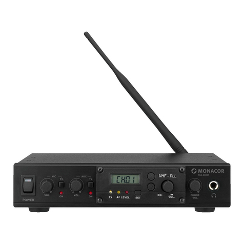
Monacor JTS RU-G3TB/5 User manual

Monacor

Monacor JTS RU-G3TB/5 User manual

Monacor VB-120VP User manual

Monacor

Monacor VB-120VP User manual

Monacor AV-100TX User manual

Monacor

Monacor AV-100TX User manual

Monacor IMG Stageline TXS-900HSE User manual

Monacor

Monacor IMG Stageline TXS-900HSE User manual

Monacor VB-100VPD User manual

Monacor

Monacor VB-100VPD User manual

Monacor Security VB-100VPD User manual

Monacor

Monacor Security VB-100VPD User manual

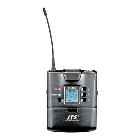
Monacor JTS R-4TBM/5 User manual

Monacor

Monacor JTS R-4TBM/5 User manual

Monacor img Stage Line TXS-420LT User manual

Monacor

Monacor img Stage Line TXS-420LT User manual

Monacor JTS RU-850TB/5 User manual

Monacor

Monacor JTS RU-850TB/5 User manual

Monacor JTS T-850B/1 User manual

Monacor

Monacor JTS T-850B/1 User manual

Monacor JTS TG-10STX/1 User manual

Monacor

Monacor JTS TG-10STX/1 User manual

Monacor JTS TG-10STX 1 User manual

Monacor

Monacor JTS TG-10STX 1 User manual

Monacor img Stage Line TXS-820HSE User manual

Monacor

Monacor img Stage Line TXS-820HSE User manual

Monacor IMG STAGELINE TXS-891HSE User manual

Monacor

Monacor IMG STAGELINE TXS-891HSE User manual

Monacor VB-200USB User manual

Monacor

Monacor VB-200USB User manual

Monacor IMG Stage Line TXS-820LT User manual

Monacor

Monacor IMG Stage Line TXS-820LT User manual

Monacor AVM-252TX User manual

Monacor

Monacor AVM-252TX User manual

Monacor JTS IN-264TB/2 User manual

Monacor

Monacor JTS IN-264TB/2 User manual

Monacor JTS PT-920BG User manual

Monacor

Monacor JTS PT-920BG User manual

Monacor img Stage Line ATS-162T User manual

Monacor

Monacor img Stage Line ATS-162T User manual

Monacor TW-220SET User manual

Monacor

Monacor TW-220SET User manual

Monacor IMG STAGELINE TXS-895HT User manual

Monacor

Monacor IMG STAGELINE TXS-895HT User manual

Monacor JTS PT-920BG/5 User manual

Monacor

Monacor JTS PT-920BG/5 User manual

Monacor IMG STAGELINE TXS-820LT User manual

Monacor

Monacor IMG STAGELINE TXS-820LT User manual

Popular Transmitter manuals by other brands

HK Instruments DPT2500-R8 Series Technical data

HK Instruments

HK Instruments DPT2500-R8 Series Technical data

Oppermann Regelgeräte SENSO-X PPX manual

Oppermann Regelgeräte

Oppermann Regelgeräte SENSO-X PPX manual

KATEK TeleAlarm NurseCall N86 user manual

KATEK

KATEK TeleAlarm NurseCall N86 user manual

Panasonic TY-3D30TRW specification

Panasonic

Panasonic TY-3D30TRW specification

Balluff BSP B A1A-S4 Series user guide

Balluff

Balluff BSP B A1A-S4 Series user guide

Oaktree Products HomeAware HA360VPT Quick setup guide

Oaktree Products

Oaktree Products HomeAware HA360VPT Quick setup guide

Emerson Rosemount 3051N Reference manual

Emerson

Emerson Rosemount 3051N Reference manual

Pyropress PYRP-28 Installation, operation and maintenance manual

Pyropress

Pyropress PYRP-28 Installation, operation and maintenance manual

NXP Semiconductors OL2300 user manual

NXP Semiconductors

NXP Semiconductors OL2300 user manual

Rain Bird TBOS Technotes

Rain Bird

Rain Bird TBOS Technotes

AMG AMG4723-CWDMn-MP instruction manual

AMG

AMG AMG4723-CWDMn-MP instruction manual

Kimo CA 310 user manual

Kimo

Kimo CA 310 user manual

Acromag TT231-0600 user manual

Acromag

Acromag TT231-0600 user manual

FONESTAR BT-CONVERTER-MULTI quick start guide

FONESTAR

FONESTAR BT-CONVERTER-MULTI quick start guide

Intec PolyGard 2 DT6 user manual

Intec

Intec PolyGard 2 DT6 user manual

Freelap TX TOUCH PRO Instructions for use

Freelap

Freelap TX TOUCH PRO Instructions for use

PreSens Microx TX3 instruction manual

PreSens

PreSens Microx TX3 instruction manual

Team Blacksheep TBS UNIFY PRO 5G8 manual

Team Blacksheep

Team Blacksheep TBS UNIFY PRO 5G8 manual

manuals.online logo
manuals.online logoBrands
  • About & Mission
  • Contact us
  • Privacy Policy
  • Terms and Conditions

Copyright 2025 Manuals.Online. All Rights Reserved.