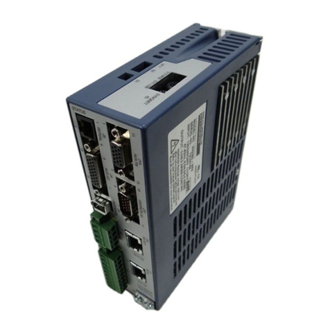
Moog T200 User manual

-~
ARTISAN
®
~I
TECHNOLOGY
GROUP
Your definitive source
for
quality
pre-owned
equipment.
Artisan Technology
Group
Full-service,
independent
repair
center
with
experienced
engineers
and
technicians
on staff.
We
buy
your
excess,
underutilized,
and
idle
equipment
along
with
credit
for
buybacks
and
trade-ins
.
Custom
engineering
so
your
equipment
works
exactly as
you
specify.
•
Critical
and
expedited
services
•
Leasing
/
Rentals/
Demos
• In
stock/
Ready-to-ship
•
!TAR-certified
secure
asset
solutions
Expert
team
ITrust
guarantee
I
100%
satisfaction
All
tr
ademarks,
br
a
nd
names, a
nd
br
a
nd
s a
pp
earing here
in
are
th
e property of
th
e
ir
r
es
pecti
ve
ow
ner
s.
Find the Moog / Berkeley Process Control T200-410G-0P81 at our website: Click HERE

T200
PROGRAMMABLE
SERVO DRIVE
USER'S MANUAL
C27095-001
Artisan Technology Group - Quality Instrumentation ... Guaranteed | (888) 88-SOURCE | www.artisantg.com

T200 User's Manual
PAGE II
This page is intentionally left blank.
Artisan Technology Group - Quality Instrumentation ... Guaranteed | (888) 88-SOURCE | www.artisantg.com

T200 User's Manual
PAGE III
T200 Servo-Drive Manual Overview
This manual is broken into 11 sections and 1 Appendix.
Section 1 is an overview of the functionality of the T200 Product Family. It outlines technical features and data of the
T200.
Section 2 is description of critical safety issues. It also outlines particular installation and configuration items that the
user must implement if the target machine installationis required to be CE-Marked. This section should be read by all
users, especially those who are installing a T200 for the first time.
Section 3 describes installation and wiring for the T200 and the servo-motor. It describes T200 mounting, terminal
connections and external components.
Section 4 is a description of Moog motors. It deals with motor mechanical issues. Section 4 also outlines how to
configure the T200 servo-drive for standard and non-standard motors.
Section 5 is a Quick-Start guide, for use with WinDrive, the MS-Windows setup and monitoring package.
Section 6 is a functional description of the T200. It contains explanations of how the Inputs of the T200 affect
functionality and how Outputs reflect status and other information. It describes how to tune control loops.
Section 7 is a description of the WinDrive user interface, including details on motor and optional T200 feature
configuration. It describes how to use WinDrive for tuning and diagnostics.
Section 8 is a description of the Hand Held Terminal user interface.
Section 9 contains wiring instructions on the Controller Area Network interface.
Section 10 is a Troubleshooting guide.
Section 11 contains Sales Outlet information.
Appendix A describes EMC test configurations, under which the T200 was tested for compliance with the European
Union's Electro-Magnetic-Compliance (EMC) Directive, in various T200 model and I/O configurations.
This manual describes the functionality and features of the present version of the T200 Product Family. Not all of
the described features are available in previous versions of the T200.
Information contained herein is subject to change without notification and should not be construed as a commitment by
Moog Inc. This manual is periodically reviewed and revised.
Moog Inc. assumes no responsibility for any errors or omissions in this document. Critical evaluation of the manual by
the user is welcomed. Your comments will assist us in future product documentation.
Copyright 2000 by Moog Inc. All rights reserved.
Artisan Technology Group - Quality Instrumentation ... Guaranteed | (888) 88-SOURCE | www.artisantg.com

T200 User's Manual
PAGE IV
Rev Description Date Effectivity
Preliminary Preliminary version of the T200 Manual 21/Oct/98 All
First Issue First version of the T200 Manual 31/March/99 All
Second Issue Revised version of the T200 Manual. Added
description of additional features as implemented in
A8/B8/P8 software and T200-3/4/5XXG, T200-610D,
T200-710Chardware. Added features are:
-Error logging
-Fault detection via digital outputs
-Extended regen resistor protection scheme
-Extended functionality of Stepper Mode
-Personality Plug
-Output impedance of testpoints changed from
10kΩto 100Ω
15/Sep/00 All
AFirst release under Moog Ireland Part Number
C27095-001.
Previous revisions are stated to reflect document
history.
Revised version of the T200 Manual. Added features
are:
-UL approval for T200-3/4/5XX
-Changes for WinDrive2.2 (also changes necessary
to reflect entire functionality of WinDrive)
-Added POD commands for inverting output
polarities
-Extended meaning of F3 fault (DC bus fuse blown
now included in this fault)
07/May/02 Sections 1, 7, 8,
10
Artisan Technology Group - Quality Instrumentation ... Guaranteed | (888) 88-SOURCE | www.artisantg.com

T200 User's Manual
PAGE V
Table of Contents
SECTION 1: T200 OVERVIEW..............................................................................................................................1-1
1.1 INTRODUCTION.....................................................................................................................................1-3
1.2 T200 MODELS.........................................................................................................................................1-4
1.3 ENVIRONMENTAL SPECIFICATIONS................................................................................................1-6
1.4 DESIGN STANDARDS...........................................................................................................................1-7
1.5 POWER RATINGS SPECIFICATIONS..................................................................................................1-8
1.6 GENERAL FUNCTIONAL SPECIFICATIONS.....................................................................................1-12
SECTION 2: SAFETY INSTRUCTIONS...............................................................................................................2-1
2.1 GENERAL................................................................................................................................................2-3
2.2 SAFETY REGULATIONS.......................................................................................................................2-4
2.3 SAFETY....................................................................................................................................................2-5
2.4 ELECTROMAGNETIC COMPATIBILITY (EMC)...............................................................................2-15
SECTION 3: WIRING AND INSTALLATION.....................................................................................................3-1
3.1 SYSTEM COMPONENTS.......................................................................................................................3-7
3.2 EQUIPMENT MOUNTING.....................................................................................................................3-14
3.3 POWER DISSIPATION ...........................................................................................................................3-22
3.4 T200 CONNECTOR TERMINALS .........................................................................................................3-23
3.5 GENERAL SYSTEM WIRING GUIDELINES.......................................................................................3-26
3.6 SEQUENCE OF COMPONENT WIRING RECOMMENDATIONS .....................................................3-28
3.7 THREE-PHASE A.C. MAINS POWER SOURCE CONFIGURATION.................................................3-29
3.8 SINGLE PHASE 230VA.C. MAINS CONFIGURATION......................................................................3-31
3.9 SINGLE PHASE 120VA.C. MAINS CONFIGURATION......................................................................3-33
3.10 PROVIDING D.C. BUS POWER FROM A T200-X10 UNIT TO T200-X00 UNITS ............................3-35
3.11 PARALLELING T200-X10 UNITS THROUGH THE D.C. BUS...........................................................3-42
3.12 DAISYCHAINING CONTROL-BACKUP POWER CONNECTIONS TO T200'S ...............................3-43
3.13 INTERNAL/EXTERNAL REGENERATION (REGEN) RESISTORS – CONFIGURATIONS............3-45
3.14 MOTORS - INSTALLATION..................................................................................................................3-56
3.15 T200 CONTROL INPUT AND OUTPUTS .............................................................................................3-68
3.16 INCREMENTAL ENCODER/STEPPER MOTOR INTERFACE INPUT DESCRIPTION...................3-79
3.17 ENCODER SIMULATION OUTPUT DESCRIPTION...........................................................................3-80
Artisan Technology Group - Quality Instrumentation ... Guaranteed | (888) 88-SOURCE | www.artisantg.com

T200 User's Manual
PAGE VI
3.18 COMMUNICATIONS INTERFACE WIRING AND CONFIGURATION............................................3-82
3.19 T200 USER VISUAL INDICATIONS.....................................................................................................3-90
SECTION 4 MOTOR GUIDE.................................................................................................................................4-1
4.1 MOTOR SERVO-DRIVE SYSTEM........................................................................................................4-4
4.2 GLOBAL MOTOR MODELS AND ELECTRICAL TYPES .................................................................4-4
4.3 CONFIGURING THE MOTOR IN THE T200 SERVO-DRIVE ............................................................ 4-8
4.4 MOTOR-DRIVE SELECTION................................................................................................................4-10
4.5 MOTOR PERFORMANCE DATA..........................................................................................................4-11
4.6 MOUNTING AND INSTALLATION.....................................................................................................4-13
SECTION 5: QUICK-START ..................................................................................................................................5-1
5.1 GETTING STARTED .............................................................................................................................. 5-3
SECTION 6: T200 FUNCTIONAL OVERVIEW...................................................................................................6-1
6.1 INTRODUCTION ....................................................................................................................................6-5
6.2 T200 FUNCTIONALITY OVERVIEW...................................................................................................6-6
6.3 T200 CONVENTIONS............................................................................................................................. 6-11
6.4 POWER INTERFACE SECTION............................................................................................................6-12
6.5 INPUT AND OUTPUT FUNCTIONAL DESCRIPTION .......................................................................6-17
6.6 INTERNAL FUNCTION GENERATOR ................................................................................................ 6-25
6.7 CONTROL LOOP OVERVIEW..............................................................................................................6-28
6.8 FAULT DETECTION.............................................................................................................................. 6-51
6.9 SELF PROTECTION ............................................................................................................................... 6-61
6.10 ENCODER SIMULATION FUNCTION.................................................................................................6-64
6.11 INCREMENTAL ENCODER INPUT .....................................................................................................6-66
6.12 STEPPER MOTOR INTERFACE............................................................................................................6-68
6.13 COMMUNICATIONS INTERFACES ....................................................................................................6-70
6.14 PARAMETER STORAGE....................................................................................................................... 6-79
SECTION 7: WINDRIVE.........................................................................................................................................7-1
7.1 INTRODUCTION ....................................................................................................................................7-6
7.2 WINDRIVE SOFTWARE SET-UP .........................................................................................................7-6
7.3 STARTING WINDRIVE.......................................................................................................................... 7-7
7.4 RS232 AND RS485 COMMUNICATION .............................................................................................. 7-9
7.5 PASSWORD PROTECTION................................................................................................................... 7-13
Artisan Technology Group - Quality Instrumentation ... Guaranteed | (888) 88-SOURCE | www.artisantg.com

T200 User's Manual
PAGE VII
7.6 MAIN WINDOW - FEATURES ..............................................................................................................7-16
7.7 GENERAL FEATURES...........................................................................................................................7-17
7.8 MENU OPTIONS .....................................................................................................................................7-19
7.9 WINDRIVE MONITORING FEATURES...............................................................................................7-24
7.10 DRIVE SET-UP........................................................................................................................................7-31
7.11 CONTROL LOOP CONFIGURATION AND TUNING.........................................................................7-43
7.12 INCREMENTAL ENCODER INPUT CONFIGURATION....................................................................7-51
7.13 EQUIPMENT AND PERSONAL SAFETY.............................................................................................7-52
7.14 DRIVE DISABLING................................................................................................................................7-53
7.15 PROGRAMMABLE BEHAVIOUR OF OUTPUTS................................................................................7-53
7.16 BRAKE CONTROL .................................................................................................................................7-54
7.17 TROUBLE SHOOTING...........................................................................................................................7-54
SECTION 8: HAND-HELD-TERMINAL INTERFACE......................................................................................8-1
8.1 HAND HELD TERMINAL INTERFACE ("POD" MODE)....................................................................8-3
8.2 SERVO-DRIVE INITIALIZATION ........................................................................................................8-5
8.3 SERVO-DRIVE TUNING........................................................................................................................8-9
8.4 T200 HAND HELD TERMINAL COMMAND SET...............................................................................8-10
SECTION 9: CAN INSTALLATION......................................................................................................................9-1
9.1 INTRODUCTION.....................................................................................................................................9-3
9.2 CAN CABLE WIRING ............................................................................................................................9-4
SECTION 10: TROUBLE-SHOOTING GUIDE ...................................................................................................10-1
10.1 INTRODUCTION.....................................................................................................................................10-4
10.2 POWER STATUS LED'S NOT ILLUMINATED....................................................................................10-5
10.3 SEVEN-SEGMENT DISPLAY STATUS................................................................................................10-7
10.4 'F' SYMBOL FOLLOWED BY NUMBER ON SEVEN-SEGMENT DISPLAY (FAULTS) .................10-8
10.5 'U' SYMBOLFOLLOWED BY NUMBER ON SEVEN-SEGMENT DISPLAY (WARNINGS) ..........10-15
10.6 OTHER PROBLEM SOURCES...............................................................................................................10-26
SECTION 11: USER INFORMATON....................................................................................................................11-1
11.1 TECHNICAL SUPPORT..........................................................................................................................11-3
APPENDIX A: EMC TEST CONFIGURATIONS................................................................................................... A-1
Artisan Technology Group - Quality Instrumentation ... Guaranteed | (888) 88-SOURCE | www.artisantg.com

T200 User's Manual
PAGE VIII
This page is intentionally left blank.
Artisan Technology Group - Quality Instrumentation ... Guaranteed | (888) 88-SOURCE | www.artisantg.com

SECTION 1: T200 OVERVIEW T200 User's Manual
PAGE 1-1
SECTION 1: T200 OVERVIEW
C27095-001
Artisan Technology Group - Quality Instrumentation ... Guaranteed | (888) 88-SOURCE | www.artisantg.com

T200 User's Manual SECTION 1: T200 OVERVIEW
PAGE 1-2
TABLE OF CONTENTS
SECTION 1: T200 Overview ....................................................................................................................................1-1
1.1 INTRODUCTION.................................................................................................................................................1-3
1.2 T200 MODELS..................................................................................................................................................1-4
1.3 ENVIRONMENTAL SPECIFICATIONS.................................................................................................................1-6
1.4 DESIGN STANDARDS.........................................................................................................................................1-7
1.5 POWER RATINGS SPECIFICATIONS..................................................................................................................1-8
1.5.1 Units with A.C. Mains Input Interface (T200-310 to T200-710)..............................................................1-9
1.5.2 Units with D.C. Bus Input Interface (T200-300, T200-400, T200-500) .................................................1-10
1.5.3 Optional Control Logic Backup Power...................................................................................................1-10
1.5.4 Power Amplifier......................................................................................................................................1-11
1.6 GENERAL FUNCTIONAL SPECIFICATIONS.....................................................................................................1-12
1.6.1 Digital Inputs ..........................................................................................................................................1-12
1.6.2 Digital Outputs........................................................................................................................................1-13
1.6.3 Other I/O.................................................................................................................................................1-13
1.6.4 Software Control Modes.........................................................................................................................1-14
Artisan Technology Group - Quality Instrumentation ... Guaranteed | (888) 88-SOURCE | www.artisantg.com

SECTION 1: T200 OVERVIEW T200 User's Manual
PAGE 1-3
1.1 Introduction
This section gives an overview of the available T200 models, ratings and general specifications. Detailed outlines of
installation and wiring, functionality, user interfaces and other technical data are given in later sections.
CAUTION: Repairs or modifications to the product by anyone other than a Moog authorized
repair facility may create unsafe operating conditions and will invalidate the product
warranty.
Artisan Technology Group - Quality Instrumentation ... Guaranteed | (888) 88-SOURCE | www.artisantg.com

T200 User's Manual SECTION 1: T200 OVERVIEW
PAGE 1-4
1.2 T200 Models
The T200 family is available in eight base models. These eight models cover a range of output current ratings and
include units either with or without integral high voltage power supplies as shown below.
T200 Base Model Amplifier Current Rating (Arms)
Units with High Voltage Power
Supply Continuous Current Peak Current
T200-310 5 10
T200-410 10 20
T200-510 20 50
T200-610 40 80
T200-710 60 140
Units without High Voltage
Power Supply Continuous Current Peak Current
T200-300 5 10
T200-400 10 20
T200-500 20 50
Table 1.1: T200 Family Models
These devices are intended for installation in a pollution degree 2 environment.
The T200 family uses a 13 character coding system to identify the unique attributes of each model. The coding system is
shown below:
T200 -AAAB -CSW
SW
designates the Embedded Software Version
Ø
Ax for standard drive functionality
Ø
Bx for CAN Interpolation Mode functionality
Ø
Px for custom POINT motion control
(where x is the release revision number)
C
designates the Option Cards
Ø
0 for no option card
Ø
1 for POINT extended I/O card
Ø
2 - 9 reserved
B
designates the hardware revision
AAA
designates the Base Model
Ø
see description above in Table 1.1.
Artisan Technology Group - Quality Instrumentation ... Guaranteed | (888) 88-SOURCE | www.artisantg.com

SECTION 1: T200 OVERVIEW T200 User's Manual
PAGE 1-5
Moog also provides a variety of accessories for the T200. Examples include:
•Operator terminals for applications requiring a user interface
•Hand held terminal for drive configuration and diagnostics
•EMC cable brackets for securing cable and grounding shields at the T200 (see Section 3.14.5)
•Personality plug for automated drive configuration
•Quick connect cables for interconnecting drives in a multi-axis application (see Section 3.1.8)
•Preconfigured motor cables
•Backup logic power supplies
•Step down transformers
Please consult your local Moog sales office or authorized distributor for part number and availability of these or other
products.
Artisan Technology Group - Quality Instrumentation ... Guaranteed | (888) 88-SOURCE | www.artisantg.com

T200 User's Manual SECTION 1: T200 OVERVIEW
PAGE 1-6
1.3 Environmental Specifications
T200 Electronics
Temperature for transport and storage: -25 °C to 70 °C
Operating temperature: 0°C to 55 °C
Relative Humidity: 5% to 95 %, non-condensing, 1 g/m3to 25 g/m3,
in accordance with EN50178 class 3k3
Elevation: 3300feet
Derate output 2% per 1000 feet above 3300 feet
Type of protection: Components must be installed into an enclosure.
The enclosure must provide at least IP54 per standard
EN60529 or equivalent.
Installed position: Vertical only.
Overvoltage protection class: Category 2 per standard VDE0110 / IEC664
Noise: Overall noise depends on the user installation and cabinet.
Noise from the electronic components is less than 55dBA.
Artisan Technology Group - Quality Instrumentation ... Guaranteed | (888) 88-SOURCE | www.artisantg.com

SECTION 1: T200 OVERVIEW T200 User's Manual
PAGE 1-7
1.4 Design Standards
The T200 has been designed to EN50178. It is CE-Marked under the EU's Low Voltage Directive. It has been designed
to allow easy compliance of customer's machines under the EU's EMC Directive (measures as directed in this manual
have to be taken to ensure EMC compliance). It is designed to the UL508C standard. T200 models –3xx, -4xx and –5xx
are UL-marked. UL is pending on the –610/710.
The T200 is considered professional equipment. Professional equipment is defined as equipment for use in trades,
professions, or industries and which is not intended for sale to the general public.
The T200 has been designed to the following specific standards:
Guidelines for engineering design EN 50178
Dimensioning of creepage distances and clearances EN 50178
Insulation coordination IEC 664
General safety requirements EN 50178
Reliable isolation EN 50178
Marking EN 50178
Grounding EN 50178
Overvoltage protection EN 50178
Ambient conditions IEC 68 Part 2-3, 2-6
Short-circuit strength EN 50178
Mechanical stresses IEC 68 Part 2-29
Protection by limitation of discharge energy EN 50178
Type-testing EN 50178
EMC EN55011
EN50082-2
UL UL508C with reference
to UL840
Table 1.2: T200 Design Standards
Artisan Technology Group - Quality Instrumentation ... Guaranteed | (888) 88-SOURCE | www.artisantg.com

T200 User's Manual SECTION 1: T200 OVERVIEW
PAGE 1-8
1.5 Power Ratings Specifications
The T200 family includes models with and without high voltage Power Supply Units (PSU's). These PSU's generate a
high voltage D.C. Bus by rectification of A.C. Mains. T200 models with PSU can supply D.C. Bus power to other T200
units which do not contain integral PSU's via D.C. Bus interconnect wiring. All current ratings are specified in ampere
r.m.s., unless otherwise stated.
Artisan Technology Group - Quality Instrumentation ... Guaranteed | (888) 88-SOURCE | www.artisantg.com

SECTION 1: T200 OVERVIEW T200 User's Manual
PAGE 1-9
1.5.1 Units with A.C. Mains Input Interface (T200-310 to T200-710)
All current ratings are specified in ampere r.m.s.
T200-310 T200-410 T200-510 T200-610 T200-710
AC Mains Input Range
Minimum
Maximum 100Va.c. (120Va.c. -15%)
255Va.c. (230Va.c. +10%) 195Va.c. (230Va.c. -15%)
255Va.c. (230Va.c. +10%)
Frequency Range 50..60Hz
Continuous Input Power
Three-Phase 7.5kW 15kW
Single Phase 230Va.c. 2.5kW Not Available
Single Phase 120Va.c. 1.2kW Not Available
Max Rated Input Power (for
15 seconds)
Three-Phase 230Va.c. 15kW 30kW
Single Phase 230Va.c. 5.0kW Not Available
Single Phase 120Va.c. 2.4kW Not Available
Maximum Number of T200-
X00's (units without A.C.
Mains PSU) which can be
connected to a T200-X10
four
Note that application power requirements will also set a limit on the number of T200-
X00's (i.e. units without Mains PSU) which may be connected to a T200-X10 (unit
with Mains PSU). See Section 3.10 for guidelines on how to match application
power requirements for each T200-X10 unit.
D.C. Bus Rated Continuous
Output Power
(T200-310 to T200-710) 20Ad.c. at 325Vd.c. (6.5kW)
Internal Regeneration Power
Continuous Dissipation 40W No internal regen
Peak Dissipation 2.8kW capability
External Regeneration Power
Continuous / Peak 200W / 14kW
(1 * 50Ω)600W / 14kW
(1 * 10Ω)600W / 14KW (1 * 10Ω)
1250W / 18kW (1 * 8Ω)
2000W / 28kW (2 * 10Ω)
2500W / 36kW (2 *8Ω)
Soft-start Peak Inrush
Current/Phase 7Apeak
Power Supply Fault Detection A.C. Mains not present
D.C. Bus Overvoltage
Internal Regeneration Fuse Blown
Power Supply Temperature Fault
Voltage Discharge after A.C.
Mains Removal Fast Bus Discharge function
Bleed Resistors across high voltage section
Power Sequencing Control Power Ready output provided to control power application
Table 1.3: T200-X10 Power Ratings
Artisan Technology Group - Quality Instrumentation ... Guaranteed | (888) 88-SOURCE | www.artisantg.com

T200 User's Manual SECTION 1: T200 OVERVIEW
PAGE 1-10
1.5.2 Units with D.C. Bus Input Interface (T200-300, T200-400, T200-500)
All current ratings are specified in ampere r.m.s. unless otherwise stated.
Nominal D.C. Bus Voltage 325Vd.c. (generated from rectified 230Va.c.)
D.C. Bus Maximum Voltage 400Vd.c. (generated from rectified 280Va.c.)
Maximum Continuous Input Current
T200-300 5Ad.c.
T200-400 10Ad.c.
T200-500 20Ad.c.
Table 1.4: T200-X00 Power Ratings
1.5.3 Optional Control Logic Backup Power
D.C. Bus Minimum Voltage
(below which 24Vd.c. or 120Va.c. Control-Logic
Backup supply is needed)
250Vd.c. (generated from rectified 170Va.c.)
24V Input 18Vd.c. to 36Vd.c.
2.0A inrush current /axis
1.5A steady state
Internal Resettable fuse in case where polarity has been
reversed
120Va.c. Input +10%, -15% voltage range
0.3Ar.m.s. /axis
Table 1.5: T200 Control Logic Backup Power Ratings
Artisan Technology Group - Quality Instrumentation ... Guaranteed | (888) 88-SOURCE | www.artisantg.com

SECTION 1: T200 OVERVIEW T200 User's Manual
PAGE 1-11
1.5.4 Power Amplifier
All current ratings are specified in ampere r.m.s. unless otherwise stated.
Power Amplifier Ratings (Ar.m.s.): Max. Time at Ipeak
T200-3 5Acontinuous/10Apeak 10s
T200-4 10Acontinuous/20Apeak 10s
T200-5 20Acontinuous/50Apeak 2s
T200-6 40Acontinuous/80Apeak 2s
T200-7 60Acontinuous/140Apeak 2s
Table 1.6: T200 Power Amplifier Ratings
Artisan Technology Group - Quality Instrumentation ... Guaranteed | (888) 88-SOURCE | www.artisantg.com
Table of contents
Other Moog Servo Drive manuals

Moog
Moog MSD Servo Drive Reference guide

Moog
Moog MSD User manual

Moog
Moog DR2020 Series User manual

Moog
Moog Class 5 SmartMotor User manual

Moog
Moog MSD User manual

Moog
Moog DS2000 User manual

Moog
Moog DS2020 Installation manual

Moog
Moog MSD User manual

Moog
Moog MSD C2 User manual

Moog
Moog DS2020 Mounting instructions
Popular Servo Drive manuals by other brands

Sinee
Sinee EA180 Series manual

Metronix
Metronix smartServo BL 4000-C Series Mounting instructions

Mitsubishi Electric
Mitsubishi Electric MELSERVO MR-HP30KA instruction manual

LinMot
LinMot E1400-GP-QN installation guide

YASKAWA
YASKAWA Sigma-V Series user manual

Eurotherm Drives
Eurotherm Drives 631 product manual