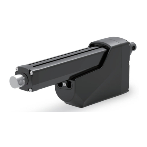
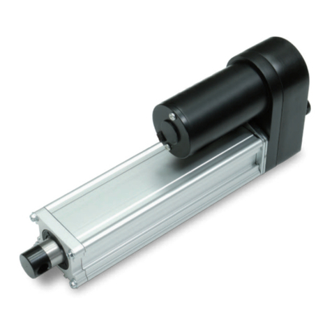
MOTECK MK35 User manual

Technical changes may be made to improve the product without notice!
2023.7_V2.2
www.moteck.com
Revision
Actuator
MK35

www.moteck.com
2
1. General
2. Important Information
3. Installation
3.1 Product label
3.2 Terminology
3.3 Working environment
3.4 Mechanical installation
3.5 Electrical installation
3.6 Installation and operation of control options
4. CAN Bus SAE J1939 Protocol
4.1 Summary
4.2 Network management
4.3 Command and status feedback
5. Troubleshooting
6. Performance and Options
6.1 Performance data
6.2 Ordering key
3
4
5
5
5
6
9
11
28
28
30
34
35
36
__________________________________________
___________________________
___________________________________
____________________________________
____________________________
___________________________
_____________________________
___________
______________________________________
____________________________
_____________________
_________________________________
_______________________________
____________________________________

www.moteck.com
3
1.1 About the manual
This manual is the mechanical and electrical installation instructions of MK35 electric linear actuator, and
also includes performance data and details of the optional specifications. Please read the instructions
carefully before installing the actuator. The installation work must be performed by qualified personnel,
which is very important.
1.2 Target readers
This manual is not provided to the end user, but provides information to the system or equipment manu-
facturer that uses this product with information on how to install, configure and maintain this product. The
system or equipment manufacturer must have qualified electromechanical personnel to perform it, and is
responsible for transmitting relevant safety messages to the end user.
1.3 Symbol description
1.4 Transport and storage
Please use the original packaging provided by MOTECK to transport and store the actuators. The tem-
perature during transportation and storage must be between -40°C to 80°C (-40°F to +176°F) and the
cargo must be protected from collision. If you find that the packaging of the delivered goods is damaged,
please check whether the actuators inside are obviously damaged, and notify the transporter. If neces-
sary, please contact the shipper or seller to discuss the disposal.
1. General
This symbol indicates important information, reminders, or safety warnings.
Symbol Descriptions

www.moteck.com
4
Only qualified personnel are allowed to carry out the mechanical and elec-
trical installation of this product. Qualified personnel should be familiar with
the mechanical or electrical installation work and have corresponding work
qualifications.
Please read this manual before installing or operating the actuators.
Do not perform mechanical installation when the actuator is powered. Com-
plete the mechanical installation first, and then perform the electrical instal-
lation.
Do not hold the extension tube when the device is powered on.
Installers and operators must wear personal safety protection according to
the site conditions. And before starting to control the action of the actuator,
it must be noted that the actuator and its connected mechanical moving
parts are not blocked by other objects, and no one enters the dangerous
area.
Strictly follow the information in this manual and the product label of the
actuators, and do not exceed the performance limits of the specification.
Never disconnect any wires or connectors during operation or when power
is applied.
If you find the actuator any malfunction or damage, please stop using it
immediately and notify qualified personnel to take corrective measures.
Do not disassemble the actuator. Otherwise, the sealing and function of the
actuator will be damaged.
There may be grease on the extension tube. It is harmless to touch the
grease, and the grease should not be removed.
●
●
●
●
●
●
●
●
●
●
2. Important Information

www.moteck.com
5
3. Installation
3.1 Product label
The product label is located on the side of the outer tube. It tells you the actuator model and basic specifi-
cation. Before performing any installation or maintenance on the actuator, please check the product label
to determine the actuator type. If you need any help from MOTECK, please provide the serial number and
actuator model.
3.2 Terminology
3.3 Working environment
%
Max. temp. +80°C Min. temp. -40°C IP67/IP69K Relative humidity 10 ~ 90%
non-condensing
Power cable
Signal cable
Anti-pull lid
Housing
Front connector
Extension tube
Rear connector
Hand crank connector
Outer tube
Product label
: MK35
: 24V DC
: 10000N (Push/Pull)
: 15%, Max. 60Sec. On/340Sec. Off
Type
Input voltage
Max. Load
Duty cycle
Model No. MK35-24-G5B-30-1000-J00-110000
IP66 (dynamic)
IP67, IP69K (static)
S/N: 1YYMMXXXXX
: MK35
: 24V DC
: 10000N (Push/Pull)
: 15%, Max. 60Sec. On/340Sec. Off
Type
Input voltage
Max. Load
Duty cycle
Model No. MK35-24-G5B-30-1000-J00-110000
IP66 (dynamic)
IP67, IP69K (static)
S/N: 1YYMMXXXXX

www.moteck.com
6
3.4 Mechanical installation
3.4.1 Safety notes
3.4.2 Basic installation considerations
(1) Always use only the holes of the front and rear connectors to install the actuator. First check the model
number on the product label (section 3.1), and then refer to the model coding (section 6.2) to identify the
connector type of the actuator, so that you can find the dimensions specification from the figures below.
● Front connector types
● Rear connector types
(2) Make sure the actuator is installed in a way that allows you to access the anti-pull lid so that it can be
removed to plug in and out the cables (section 3.4.4)
(3) Users may need to manually adjust the actuator in the future, so there must be enough free space around the
manual drive connector to operate it (section 3.4.5)
● Do not perform mechanical installation when the actuator is powered.
● Complete the mechanical installation properly before proceeding to the
electrical installation steps.
❶ Metal solid, hole ø12.2mm
❸ Metal solid, hole ø13mm
❷ Metal slot, hole ø12.2mm
❹ Metal slot, hole ø13mm
❻ SUS304 slot, hole ø12.2mm
❽ SUS304 slot, hole ø13mm
❶ Metal solid, hole ø12.2mm
❸ Metal solid, hole ø13mm
❷ Metal slot, hole ø12.2mm
❹ Metal slot, hole ø13mm
❻ SUS304 slot, hole ø12.2mm
❽ SUS304 slot, hole ø13mm
17.7 11.5
ø30
Hole Hole
ø30
1314.5
8.1
13
ø25.4
Hole
14.5 14.513
8.1
ø25.4
Hole
13 14.5
Hole
8.1
ø25.4
Hole
13
8.1
ø30
14.5

www.moteck.com
7
X
X
X X
3.4.3 Force and orientation
(1) The actuator can be installed in any orientation and can withstand push and pull loads.
(2) When installing the actuator, make ensure that the force of the load acts on the central axis of the extension tube
and rear connector.
(3) Use only solid and sized mounting pins. The mounting pins must be strong enough to support the load and
prevent it from falling off after installation.
(4) The mounting pins must be parallel to each other on the same plane, as shown in the sketch below.
(5) If the actuator is used on the equipment to rotate with the mounting pin as the axis, it must be ensured the
housing and other mechanical parts will not interfere and damage the actuator and equipment in the full range
of movement.
3.4.4 Cables and anti-pull lid
Before the actuator is shipped, the power cable and signal cable have been plugged in and the anti-pull lid has been
installed. Only the CAN Bus version (control option J00) needs to remove this lid and unplug the power cable when
the hardware address selection (see 4.2.2.2) is required. But please note that when installing the actuator, you must
ensure that there is enough space to remove the anti-pull lid with tools.

3.4.5 Installation and operation of hand crank
(1) When installing the actuator, please make sure that there is enough space between the rear connector and any
objects behind it so that the hand crank can be operated.
(2) Please use a flat-head screwdriver to remove the cover and connect with a 6mm hexagon socket.
(3) Use a wrench to operate as a hand crank.
(4) Under the maximum load of the actuator, the maximum torque required to drive the extension tube with the
hand crank is about 1.4Nm.
(5) The distance traveled by the actuator per rotation of the hand crank is related to the gear ratio options of the
actuator. Please refer to the table below.
www.moteck.com
8
3.4.3 Force and orientation
(1) The actuator can be installed in any orientation and can withstand push and pull loads.
(2) When installing the actuator, make ensure that the force of the load acts on the central axis of the extension tube
and rear connector.
(3) Use only solid and sized mounting pins. The mounting pins must be strong enough to support the load and
prevent it from falling off after installation.
(4) The mounting pins must be parallel to each other on the same plane, as shown in the sketch below.
(5) If the actuator is used on the equipment to rotate with the mounting pin as the axis, it must be ensured the
housing and other mechanical parts will not interfere and damage the actuator and equipment in the full range
of movement.
3.4.4 Cables and anti-pull lid
Before the actuator is shipped, the power cable and signal cable have been plugged in and the anti-pull lid has been
installed. Only the CAN Bus version (control option J00) needs to remove this lid and unplug the power cable when
the hardware address selection (see 4.2.2.2) is required. But please note that when installing the actuator, you must
ensure that there is enough space to remove the anti-pull lid with tools.
Gear type mm /rev
2.247
● Before using the hand crank, be sure to turn off the actuator power. Do not
apply torque exceeding 1.7Nm on the hand crank.
● Do not move the extension tube to both ends of the stroke, otherwise the
actuator might be damaged.
● Do not use any type of automatic drill or power tools to drive the manual
crank.
10
15
20
30
1.349
0.804
0.609
0.379
5
3.5 Electrical installation
3.5.1 Safety notes
3.5.2 Important information
3.5.3 Fuse specification
Install a slow-blow fuse of this specification between the actuator and the power supply for protection.
www.moteck.com
9
● It is recommended to install an emergency stop switch at a suitable location
of the power supply line.
● Do not install or wire the actuator without cutting off the power supply.
● Before controlling the action of the actuator, it must be noted that the
actuator and its connected mechanical moving parts are not blocked by
other objects, and no one enters the dangerous area.
● It is forbidden to wind the signal cable with the power cable to avoid
interference with the signal.
● Avoid using the vehicle as a ground to reduce the risk of interference.
● The longer the power cord length or the smaller the wire diameter, the
worse the voltage drop. When the voltage of the power supply is low, it is
more likely to cause insufficient voltage and cause malfunctions.
● Relays or other coils on operating equipment should have spark protection
to avoid interference.
● In order to achieve the longest service life, the actuator should not be
stopped by frequent hard collisions. Before the actuator moves to the
target position or both ends of the stroke, the user's automatic control
device should cut off the power of the motor in advance according to the
absolute position information, and use the inertia to make the actuator stop
gently.
● It is forbidden to use Pulse Width Modulation (PWM) as input power to
MK35, otherwise it will cause malfunction and cause permanent damage.
● Before using the hand crank, be sure to turn off the actuator power. Do not
apply torque exceeding 1.7Nm on the hand crank.
● Do not move the extension tube to both ends of the stroke, otherwise the
actuator might be damaged.
● Do not use any type of automatic drill or power tools to drive the manual
crank.
Input voltage
12V DC
Fuse specification
40A
24V DC 20A

3.5.4 Electrical connections
Actuator is equipped with a power cable and a signal cable. One end of each cable has been plugged and fixed
on the actuator before shipment, and the other end are bare wire contacts for customers to connect power and
signal transmission. Please check the model number on the product label (section 3.1) first, then refer to the
model coding (section 6.2) to identify the control options of the actuator, and connect the power cable and signal
cable correctly according to the description of each control option (section 3.6).
3.5.5 Wire specification of power cable and extension cord
To avoid malfunctions caused by voltage drop, the cross-section of the power cable wire must be large enough.
The cross-section of the MK35 power cable wire is 2.0mm² (14AWG) and the maximum length is 3 meters. If the
customer must connect an extension cord, the wire requirements of the extension cord are as follows.
3.5.6 Inrush current
www.moteck.com
10
● When the actuator starts, an inrush current of about 0.2 seconds will be
generated. The starting inrush current of MK35 can reach 3 times of the
maximum current under the rated load of the actuator.
● If a circuit board power supply is used, the specifications must be sufficient
to handle the inrush current. If batteries are used as the power source,
inrush current will not be a problem. Besides, the connectors, switches and
relays selected by user must also be able to withstand the inrush current.
Minimum cross section
4mm² (AWG 12)
Maximum length
4m

www.moteck.com
11
3.6 Installation and operation of control options
3.6.1 Determine control options
MK35 actuator is equipped with one of the control options in the table below. Please check the model number on
the product label (section 3.1), and then refer to the model coding (section 6.2) to identify the control options of
the actuator. Then check the corresponding sections in the table below for more details.
* Remarks: End of stroke signal output
D00
D0L
DPL
DHL
3.6.2
3.6.3
3.6.4
3.6.5
D+L 3.6.6
S0L
SPL
SHL
J00
Low current signal
J1939 CAN Bus
3.6.7
3.6.8
3.6.9
3.6.10
NPN PNP
Options Control platform Potentiometer
output Section
EoS
signal output *
Motion status
feedback
Hall signal
output
Classic
(DC control)

www.moteck.com
12
3.6.2 Control option D00 (DC control, without positioning feedback)
Option D00 controls the actuator to extend or retract by switching the polarity of the input DC power.
(1) When the actuator reaches the limit position at both ends of the stroke, it will still stop by itself, but it will not
output a signal of reaching the limit.
(2) Do not adjust the input voltage in an attempt to control the speed of the MK35 DXX control options.
(3) The D00 option does not include a signal cable, and the port has a waterproof cap.
● Wiring
● Wire definitions
Connect red wire to “Vdc +” & black wire to “Vdc -“ of DC power to
extend the actuator. Switch the polarity of DC input to retract it.
Input voltage: According to actuator voltage specification
Power
cable
DescriptionWire color
Red
Black
Definition
V+
V-
V+
V-
Fuse
Remarks: Dashed lines are connected by the customer.

www.moteck.com
13
3.6.3 Control option D0L (DC control, with EoS signal output)
In addition to all the functions included in the D00 option (section 3.6.2), the D0L option is also with an arrival signal
output when it reaches the end of stroke (EoS), so that the customer system can perform corresponding control,
such as light signal display, relay action, etc.
● Wiring
● Wire definitions
Connect red wire to “Vdc +” & black wire to “Vdc -“ of DC power to
extend the actuator. Switch the polarity of DC input to retract it.
Input voltage: According to actuator voltage specification
Power
cable
DescriptionWire color
Red
Black
Red
Black
Definition
V+
V-
Not used
Not used
White
• The stroke limit switches are open collector circuit, and the arrival
signal output is not potential free. A pull-up resistor should be applied
in user’s control circuit (see the wiring diagram on Page 13),
the resistance of 10KΩ is recommended.
• Recommended input voltage Vcc = 5~24V
• Signal voltage during the stroke = GND (Normally closed circuit)
• End of stroke signal voltage = Vcc (Open circuit)
GND
Yellow
Blue
Not used
Not used
Connect to customer signal receiving device GND
Remarks: To use the limit arrival signal, you must keep the power supply of the actuator and the customer's Vcc power supply,
otherwise the signal will be lost.
Remarks: All dashed lines are connected by the customer.
Not used
Not used
GND
Extend EoS
Retract EoS
Not used
Not used
Vcc
V+
V-
Resistor
Fuse
Customer signal receiving device
Vcc
Resistor
Green Extend EoS
output
Orange Retract EoS
output
Signal
cable

www.moteck.com
14
3.6.4 Control option DPL
(DC control, with EoS signal output and potentiometer positioning output)
In addition to all the functions included in the D00 and D0L options (section 3.6.2 & 3.6.3), the DPL option is also
equipped with a potentiometer, which allows the user's control device to know the absolute position of the actuator
at any time, and can be used to determine the speed and direction of the actuator's movement.
● Wiring
The potential value of the mechanical potentiometer can be measured
through the signal wires. This value is only related to the stroke position.
Even if the power supply is interrupted, it will not change the measurable
potential value.
Remarks: All dashed lines are connected by the customer.
Vin
POT output
GND
Extend EoS
Retract EoS
Not used
Not used
Vcc
V+
V-
Resistor
Fuse
Customer signal receiving device
Vcc
Resistor

• The stroke limit switches are open collector circuit, and the arrival
signal output is not potential free. A pull-up resistor should be applied
in user’s control circuit (see the wiring diagram on Page 14),
the resistance of 10KΩ is recommended.
• Recommended input voltage Vcc = 5~24V
• Signal voltage during the stroke = GND (Normally closed circuit)
• End of stroke signal voltage = Vcc (Open circuit)
Remarks: To use the limit arrival signal, you must keep the power supply of the actuator and the customer's Vcc power supply,
otherwise the signal will be lost.
Green Extend EoS
output
Orange Retract EoS
output
www.moteck.com
15
● Wire definitions: DPL
Yellow The recommended voltage: 5~32V
1. Potentiometer specification:
- 10K ohm, 10 turns.
- Tolerance ±5%
2. Output voltage: The voltage (resistance) between Blue and White
increases linearly from about 0 when the actuator extends from
the lower limit position, and decreases when it retracts.
3. There are different resolutions according to the stroke
length (as table below)
4. The potential value can be measured through the POT output and
GND wires.
Actuator extends
Y
W
B
Stroke range (mm)
100~450
451~950
Vin
Resolution (ohm/mm)
20
10
Connect red wire to “Vdc +” & black wire to “Vdc -“ of DC power to
extend the actuator. Switch the polarity of DC input to retract it.
Input voltage: According to actuator voltage specification
Power
cable
DescriptionWire color
Red
Black
Red
Black
Definition
V+
V-
Not used
Not used
Blue POT output
White GND
Signal GND. Both for POT output and customer signal receiving device.
Signal
cable

www.moteck.com
16
3.6.5 Control option DHL
(DC control, with EoS signal output and dual Hall effect sensors feedback-NPN type)
In addition to all the functions of the D00 and D0L options (section 3.6.2 & 3.6.3), the DHL option is also equipped
with dual Hall effect sensors, providing an NPN-type feedback circuit.
● Wiring
The Hall feedback is a relative positioning. DHL version of the actuator
does not have built-in memory, and the position signal will disappear after
power-off. The customer's control device must have the function of reading
the position signal and recording it.
Remarks: All dashed lines are connected by the customer.
Hall 2 output
Hall 1 output
GND
Extend EoS
Retract EoS
Not used
Not used
Vcc
V+
V-
Resistor
Fuse
Customer signal receiving device
Vcc
Resistor

www.moteck.com
17
● Wire definitions: DHL
• The stroke limit switches are open collector circuit, and the arrival
signal output is not potential free. A pull-up resistor should be applied
in user’s control circuit (see the wiring diagram on Page 16),
the resistance of 10KΩ is recommended.
• Recommended input voltage Vcc = 5~24V
• Signal voltage during the stroke = GND (Normally closed circuit)
• End of stroke signal voltage = Vcc (Open circuit)
Remarks: To use the limit arrival signal, you must keep the power supply of the actuator and the customer's Vcc power supply,
otherwise the signal will be lost.
Green Extend EoS
output
Orange Retract EoS
output
White
Signal GND. Both for Hall output and customer signal receiving device.
Connect red wire to “Vdc +” & black wire to “Vdc -“ of DC power to
extend the actuator. Switch the polarity of DC input to retract it.
Input voltage: According to actuator voltage specification
Power
cable
DescriptionWire color
Red
Black
Red
Black
Definition
V+
V-
Not used
Not used
Yellow Hall 2 output
Blue Hall 1 output
Hall 1
Hall 2
High
Low
High
Low
Hall 1
Hall 2
High
Low
High
Low
Actuator extends Actuator retracts
Vout High = Vdc+ (DC Power) - 1.2V, Imax 12.7mA
Vout Low = GND
Hall signal data:
Resolution:
GND
15
20
Gear ratio
30
10
05
2.9552
3.9028
Resolution (Pulse/mm)
6.2588
1.7601
1.0571
Signal
cable

www.moteck.com
18
3.6.6 Control option D+L
(DC control, with EoS signal output and dual Hall effect sensors feedback-PNP type)
In addition to all the functions of the D00 and D0L options (section 3.6.2 & 3.6.3), the D+L option is also equipped
with dual Hall effect sensors, providing an PNP-type feedback circuit.
● Wiring
Remarks: All dashed lines are connected by the customer.
Hall 2 output
Hall 1 output
GND
Extend EoS
Retract EoS
Not used
Not used
Vcc
V+
V-
Resistor
Fuse
Customer signal receiving device
Vcc
Resistor
The Hall feedback is a relative positioning. D+L version of the actuator
does not have built-in memory, and the position signal will disappear after
power-off. The customer's control device must have the function of reading
the position signal and recording it.

www.moteck.com
19
● Wire definitions: D+L
• The stroke limit switches are open collector circuit, and the arrival
signal output is not potential free. A pull-up resistor should be applied
in user’s control circuit (see the wiring diagram on Page 18),
the resistance of 10KΩ is recommended.
• Recommended input voltage Vcc = 5~24V
• Signal voltage during the stroke = GND (Normally closed circuit)
• End of stroke signal voltage = Vcc (Open circuit)
Remarks: To use the limit arrival signal, you must keep the power supply of the actuator and the customer's Vcc power supply,
otherwise the signal will be lost.
Green Extend EoS
output
Orange Retract EoS
output
White
Signal GND. Both for Hall output and customer signal receiving device.
Connect red wire to “Vdc +” & black wire to “Vdc -“ of DC power to
extend the actuator. Switch the polarity of DC input to retract it.
Input voltage: According to actuator voltage specification
Power
cable
DescriptionWire color
Red
Black
Red
Black
Definition
V+
V-
Not used
Not used
Yellow Hall 2 output
Blue Hall 1 output
Hall 1
Hall 2
High
Low
High
Low
Hall 1
Hall 2
High
Low
High
Low
Actuator extends Actuator retracts
Vout High = Vdc+ (DC Power) - 1.2V, Imax 12.7mA
Vout Low = GND
Hall signal data:
Resolution:
GND
15
20
Gear ratio
30
10
05
2.9552
3.9028
Resolution (Pulse/mm)
6.2588
1.7601
1.0571
Signal
cable

www.moteck.com
20
3.6.7 Control option S0L (Low current signal control, with EoS signal output)
Option S0L uses a low current (<10mA) input signal to control the extension, retraction or stop of the actuator,
cannot be switched the polarity of the input DC power, and there is an arrival signal output when it reaches the end
of stroke (EoS). However, if the user does not need EoS signal, these two signal output wires can be ignored and
unconnected. This does not affect the other functions of the actuator, and the actuator will still stop when it reaches
the limit positions at both ends of the stroke.
In addition, the actuator also has the following functions:
● At both ends of the mechanical stroke and within the full stroke range, when the current exceeds the factory
preset value of the rated load (overload condition), the actuator will automatically stop.
● When the input voltage exceeds its normal working range, the actuator will stop running. After the correct
voltage input is restored, the operation signal must be re-sent to restore control.
● With automatic soft start function, make the equipment move smoothly.
● Wiring
● The polarity of the input DC power must be fixed in accordance with the
specified connection method, and the polarity cannot be switched at any
time.
● It is forbidden to adjust the input voltage in an attempt to control the speed
of the MK35 SXX control options. The battery or full-wave rectified DC
power used must be within acceptable voltage range, otherwise the
actuator will stop operating.
Remarks: All dashed lines are connected by the customer.
Hall 2 output
Hall 1 output
GND
Extend EoS
Retract EoS
Vcc
Resistor
Customer signal receiving device
Vcc
Resistor
V+
V-
Fuse
Extend
Retract
Other manuals for MK35
1
Table of contents
Other MOTECK Controllers manuals

MOTECK
MOTECK ID12 User manual

MOTECK
MOTECK ID12 User manual

MOTECK
MOTECK CB3T Operational manual

MOTECK
MOTECK FD60 User manual

MOTECK
MOTECK ID10 User manual

MOTECK
MOTECK 01US10 User manual

MOTECK
MOTECK IA5 User manual

MOTECK
MOTECK ID11 User manual

MOTECK
MOTECK ID11 User manual

MOTECK
MOTECK 01US12 User manual