www.moteck.com
3
Yellow (+), White (-)
or
Yellow (-), White (+)
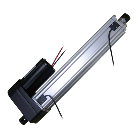
●With Potentiometer (POT) absolute positioning feedback
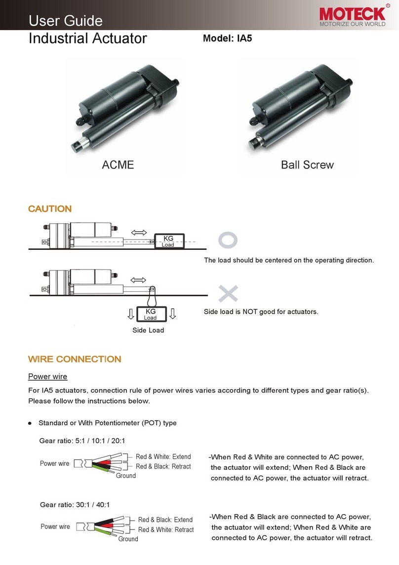
Connect red wire to “Vdc +” & black wire to “Vdc -“ of DC power to
extend the actuator. Switch the polarity of DC input to retract it.
Power
wires
Comments
Input voltage 70V max.
Potentiometer specification:
- Potentiometer 10K ohm, 10 turns.
- Total resistance tolerance ±5%
Output voltage: Between 0 ~ Vin
Potentiometer resistance:
Definition
DC Power
GND
Vin
Actuator extends
Y
W
B
The resistance between blue and white wires increases when the actuator
extends, and decreases when it retracts.
OUTPUT
Signal
wires 150 (6”)
100 (4”)
200 (8”)
Stroke (mm)
300 (12”)
450 (18”)
600 (24”)
Red
Black
Wire color
White
Yellow
Blue
0.3 ~ 8.0K
0.3 ~ 8.5K
0.3 ~ 9.1K
0.3 ~ 8.6K
0.3 ~ 9.2K
Resistance (tolerance: ±0.3KΩ)
0.3 ~ 9.8K
●External Reed Sensors
With external reed sensors, select either yellow or white wire as common point, and the other one will
be signal output.
How to change the position of reed sensor:
Step 1. Loosen the screws.
Step 2. Slide sensor to the correct position.
Step 3. Tighten the screws and make sure the sensor is fixed.
SAFETY DECLARATION
This appliance cannot be used by children or persons with reduced physical, sensory or mental
capabilities, or lack of experience and knowledge, unless they have been given supervision or
instruction.
MOTECK MO-I-0005-V1.1
Terms of Use
The user is responsible for the suitability of MOTECK products, and the products listed on the MOTECK website are subject to change without notice. MOTECK reserves the right to terminate sales or
delete any products displayed on the website or listed in its catalog.
