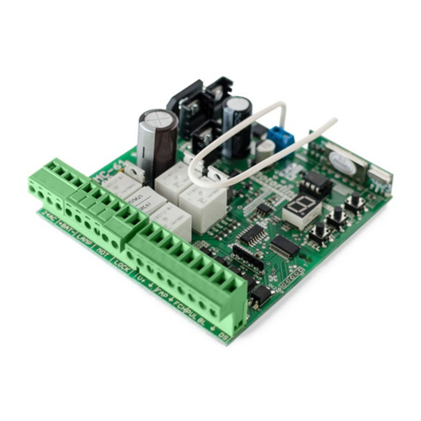
Motorline professional MC112N Use and care manual
Other Motorline professional Control Unit manuals
Motorline professional
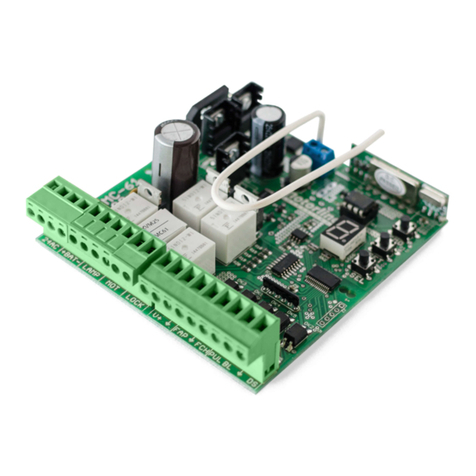
Motorline professional MC61PL Instruction Manual
Motorline professional
Motorline professional MC7 Operation and installation manual
Motorline professional
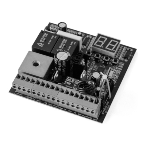
Motorline professional MC61BR Operation and installation manual
Motorline professional
Motorline professional MC41SP Instruction Manual
Motorline professional
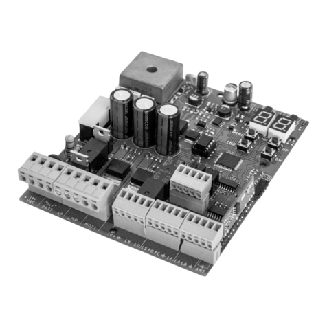
Motorline professional MC60 Use and care manual
Motorline professional
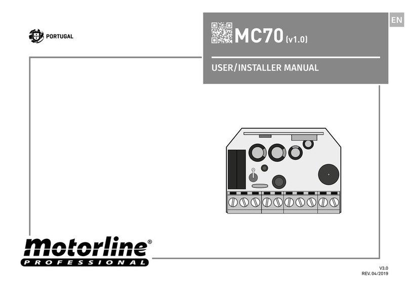
Motorline professional MC70 Instruction Manual
Motorline professional
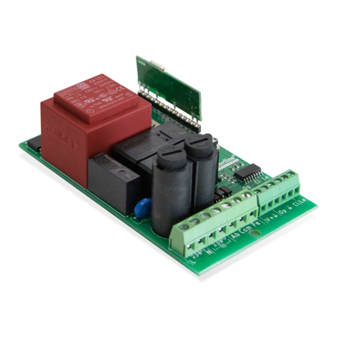
Motorline professional MC75 Use and care manual
Motorline professional
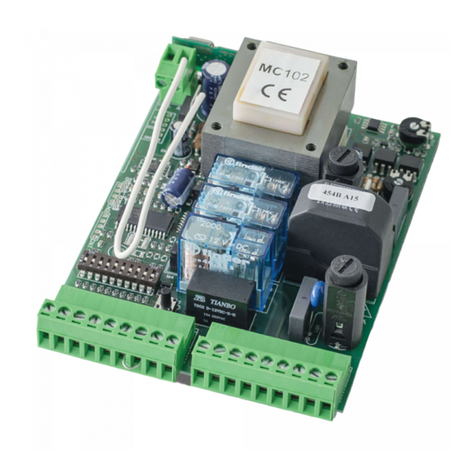
Motorline professional MC102 Instruction Manual
Motorline professional
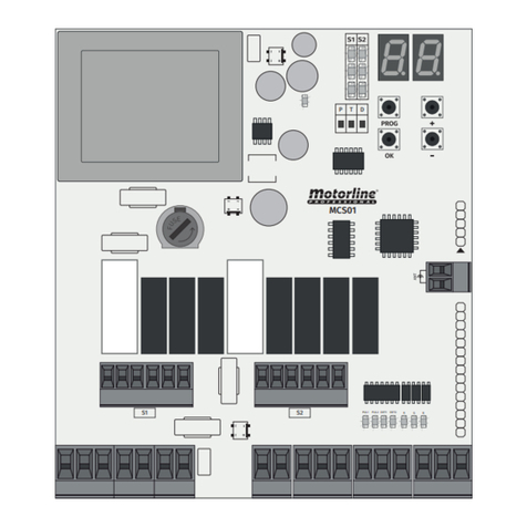
Motorline professional MCS01 Instruction Manual

Motorline professional
Motorline professional MC4 EVO User manual

Motorline professional
Motorline professional MC70 EVO Instruction Manual

Motorline professional
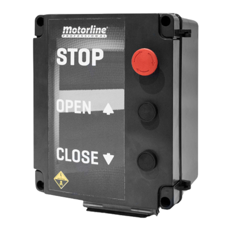
Motorline professional MC61PL Operation and installation manual
Motorline professional
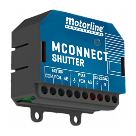
Motorline professional MC112PR User manual
Motorline professional
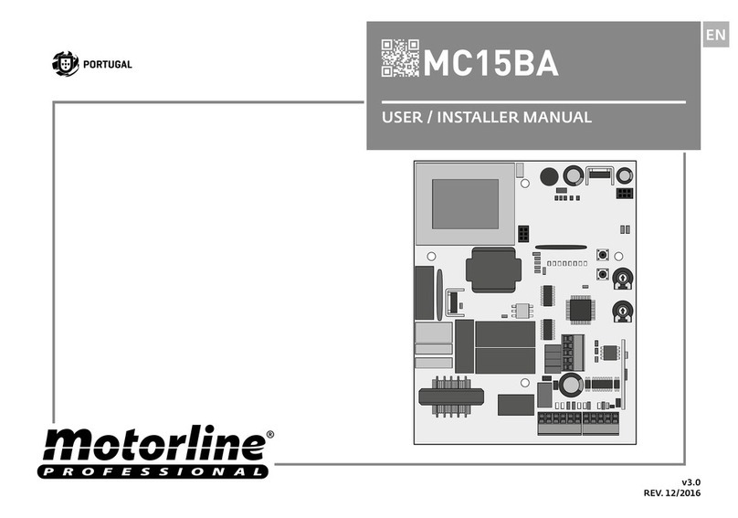
Motorline professional MCONNECT SHUTTER Use and care manual
Motorline professional
Motorline professional MC15BA Instruction Manual

Motorline professional
Motorline professional MC61SE Operation and installation manual
Popular Control Unit manuals by other brands

Festo
Festo Compact Performance CP-FB6-E Brief description

Elo TouchSystems
Elo TouchSystems DMS-SA19P-EXTME Quick installation guide

JS Automation
JS Automation MPC3034A user manual

JAUDT
JAUDT SW GII 6406 Series Translation of the original operating instructions

Spektrum
Spektrum Air Module System manual

BOC Edwards
BOC Edwards Q Series instruction manual

KHADAS
KHADAS BT Magic quick start

Etherma
Etherma eNEXHO-IL Assembly and operating instructions

PMFoundations
PMFoundations Attenuverter Assembly guide

GEA
GEA VARIVENT Operating instruction

Walther Systemtechnik
Walther Systemtechnik VMS-05 Assembly instructions

Altronix
Altronix LINQ8PD Installation and programming manual


