Moza Air 2 User manual

User Manual
用户手册

MOZA Air 2 Overview 1
Air 2 Installation 2
Attaching the Tripod 2
Installing Batteries 2
Mounting the Camera 3
Connecting Camera Control Cable 4
Installing the Support Rod 4
Mounting the Riser Plate 5
Balance Adjustment 6
Lock the Roll Axis 6
Balancing the Camera 6
Balancing the Tilt Axis 6
Balancing the Roll Axis 7
Balancing the Pan Axis 7
Buttons and OLED Display 8
Button Functions 8
Main Interface 8
Menu Description 9
Features Description
Extension
Smartphone and PC connection
Install the Phone Holder
FirmwareUpgrade
11
11Camera Control
Motor Output 13
Follow mode,FPV,Sport Gear Mode 14
Manual Positioning 15
Button Customization 15
Inception Mode 15
16Balance Check
17Sensor Calibration
18Language Switch
User Configuration
Management
18
18
19
19
19
20
21
Contents
SPECS

21
22
22
22
23
24
24
25
26
26
26
26
27
27
28
28
29
30
32
32
34
35
36
36
36
37
38
39
39
40
40
40
40
41
目录
认识Air 2
安装Air 2
三脚架的安装和使用
电池的安装拆卸
相机的安装和拆卸
相机控制线的安装
跟焦安装管的安装和拆卸
增高组件的使用
平衡调节
锁定横滚轴
快装板前后调节
俯仰臂调节
横滚臂调节
航向臂调节
按键功能和屏幕显示
按键定义
主界面说明
菜单说明
功能说明
相机控制
电机出力
跟随模式、态极、极速跟随
手动定位
按键自定义
盗梦空间
平衡检查
传感器校准
切换显示语言
用户配置管理
扩展使用
连接智能手机或电脑
安装手机支架
固件升级
规格参数
1
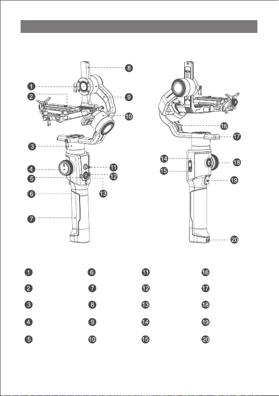
MOZA AIR 2 Overview
Tilt Motor
Mechanical Memory
Quick Release System
Pan Motor
Wheel
Dial
Fn Button
Tune/Firmware
Upgrade Port
DC Input Port
3/8” Extension
Port
Smart Trigger
Battery Hatch
Battery Hatch
Lock
Tilt Arm
Roll Arm
Roll Motor Lock
Pan Arm
Roll Motor
Joystick
M Button
Power Button

2
Attaching the Tripod
2 screw holes are equipped at the bottom of grip: 1/4” for mini tripod and 3/8” for
large accessories like slider and big tripod. Screw the mini tripod, then expand as
shown below.
a. Hold the battery hatch slightly, push the lock downward, slide the hatch as
shown below and then release the lock.
b. Insert the batteries one by one as shown.
c. Cover the battery hatch.
AIR 2 Installation
1
2
3
4
Installing Batteries
Note: Please pay attention to the battery poles for fear of short circuit.
Table of contents
Other Moza Camera Accessories manuals


Popular Camera Accessories manuals by other brands


Trojan
Trojan GC2 48V quick start guide

Calumet
Calumet 7100 Series CK7114 operating instructions

Ropox
Ropox 4Single Series User manual and installation instructions

Cambo
Cambo Wide DS Digital Series Main operating instructions

Samsung
Samsung SHG-120 Specification sheet

Ryobi
Ryobi BPL-1820 Owner's operating manual