MPK VisionVent M pro Manual

1
Einbau- und Bedienungsanleitung
D
Dachhaube VisionVent M pro - Modell 4751P/ 4753P
Sondermodelle 44P/ 4400P, 46P/ 4600P
Stand: Juni 2013 Technische Änderungen vorbehalten!
Metall- und Plastikverarbeitungs- GmbH & Co. KG Kierspe
Internet: www.mpk-kierspe.de
ISO 9001:2008
Zert.-Nr. 01 100 89747 ISO 14001:2004
Zert.-Nr. 01 104 069609
2
Wirempfehlen,dieDachhaubeineinerauthorisiertenFachwerkstattmontieren
zu lassen.
Lesen Sie die Anleitung vor der Montage der Dachhaube gründlich durch.
Abbildungen
1 23
4 5 6
7 8 9
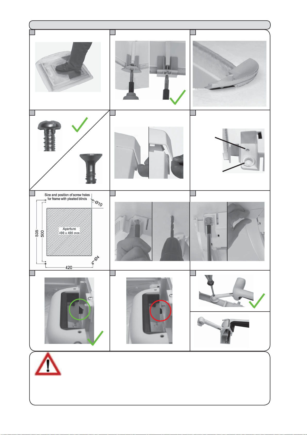
Loch für
Schraube
Loch für
Kunststoffschraube
Wirweisendaraufhin, daß wir für Schäden oder Verletzungen durch unsachgemäßeMontage
und/ oder Bedienung keine Gewährleistungshaftung übernehmen.
Bei autretenden Fehlern bitte umgehend eine Fachwerkstatt aufsuchen.
10 11 12
falsch
falsch
falsch
falsch
falsch

3
Montagehinweise
Warnhinweis!
Einbauposition
Dachausschnitt
Dachdicken
Einbaurichtung
Schrauben
- Oberrahmen:
- Innenrahmen:
Dichtung
Montage
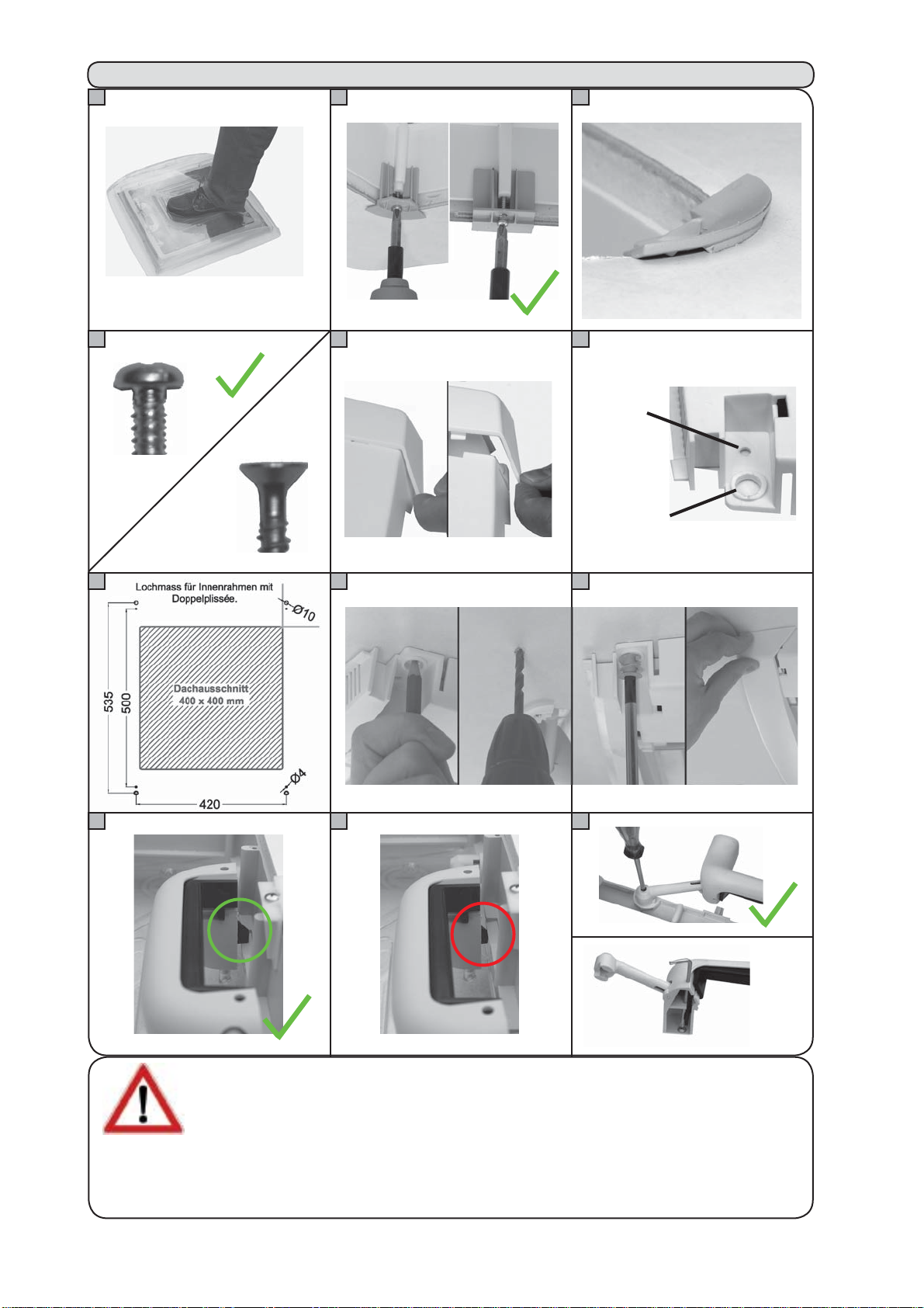
Betreten Sie niemals die Kuppel der Dachhaube!
(Abbildung 1)
WählenSiedieEinbaupositionso,daßkeineangrenzenden Bau-
eile(Dachreling/Antenneetc),verlegteLeitungenoderMöbelteile
im Inneren beschädigt oder in ihrer Funktion gestört werden.
Die Montage der Dachhaube ist nur an planen Innen- und Au-
ßenflächen möglich.
400x400 mm (siehe techn. Daten auf S. 5)
BittebeachtenSiedieunter lieferbareAusführungenangegebenen
Dachdicken (siehe lieferbare Ausführungen auf S. 6).
Dachhaube immer mit Ausstellern in Fahrtrichtung montieren
(d. h. Griffe jeweils vorne und hinten)
Linsenblechschrauben 3,5 mm/ Kopf nach DIN ISO 7049
(DIN 7981)
Wählen Sie die Schraubenlänge je nach Dachdicke so, daß sie
sichca.10mmindenSchraubkanal des Oberrahmens eindrehen
lassen.
SchraubenlängefürInnenrahmenbefestigung 13 mm(oderKunst-
stoffschraube für großes Loch)
Verwenden Sie keine Senkkopfschrauben, da diese den Dach-
haubenrahmen beschädigen könnten. (Abbildung 4)
Die Dichtung ist im Lieferumfang nicht enthalten.
Bitte verwenden Sie ausschließlich dauerelastische Dichtungen,
die für den Außeneinsatz geeignet sind.
Die verwendete Dichtung darf das Material des Oberrahmens
nicht angreifen. Fragen Sie den Dichtungslieferanten. Beachten
Sie die Verarbeitungshinweise des Dichtungsherstellers.
Entfernen Sie den Innenrahmen. Bringen Sie das Dichtmaterial
im Dichtkanal des Oberrahmens auf und setzen Sie diesen von
oben in den Dachausschnitt (Aussteller in Fahrtrichtung).
Verschrauben Sie die 8 mitgelieferten Clipse von innen an den
SchraubdomendesOberrahmens (Abbildung2),d.h. dievierEck-
clipseandenEck-Schraubdomen,dieviergeradenClipseanden
mittleren Schraubdomen. (Schrauben nicht im Lieferumfang)
Vorsicht: Ziehen Sie die Schrauben nicht zu fest an, sondern nur
soweit, bis die Clipse leicht zu kippen anfangen. (Abbildung 3).
Max. Drehmoment 0,5 Nm
4
Montagehinweise
Montage
Bedienung
Zwangsbelüftung
Vor Fahrantritt
Eswirdempfohlen, den InnenrahmenmitZugrichtungderPlissees
quer zur Fahrrichtung zu montieren, um dieAussteller der Haube
nicht zu behindern.
ZurMontage desInnenrahmensentfernenSievorsichtigdiebeiden
seitlichenAbdeckungen (Abbildung 5), so daß die Schraublöcher
freiliegen.
In jeder Ecke sind zwei verschieden große Schraublöcher für
(Abbildung 6) unterschiedliche Befestigungsoptionen.
VerwendenSieLinsenblechschrauben(nichtmitgeliefert-sieheSeite
2),wennim BereichIhresDachausschnittseine massiveHolzeinlage
vorhanden ist. Überprüfen Sie anhand der Skizze (Abbildung 7),
ob die Holzeinlage breit genug ist, um die Schrauben im Bereich
der kleinen Schraublöcher noch aufzunehmen. Innenrahmen mittig
in den Ausschnitt setzen und direkt in die Holzeinlagen schrauben.
Schrauben von Hand festziehen. Nicht überdrehen!
Verwenden Sie die vier mitgelieferten Kunststoffschrauben, wenn
keineHolzeinlage vorhanden ist und die Verschraubung nur in die
dünne Sperrholz-/ Polyester-Schicht erfolgen soll.
Den Innenrahmen mittig in denAusschnitt setzen und die Bohrlö-
cher mittig innerhalb der großen Schraublöcher anzeichnen.
SchraublöchervorbohrenundRahmenmittelsKunststoffschrauben
von Hand anschrauben. Nicht überdrehen!
(Abbildung 8-9)
Achtung: Beschädigen Sie auf keinen Fall dieAußenschicht des
Daches durch zu tiefe Bohrlöcher (max. 5 mm) oder zu lange
Schrauben.
Setzen Sie die seitlichen Abdeckung parallel zum Dach an, so
daß die Rastnasen in die vorgesehenen Löcher am Rahmen
eintauchen. Schieben Sie die Abdeckung parallel zum Dach in
Richtung des Rahmens bis sie hörbar einrastet, ohne diese zu
verkanten. (Abbildung 9)
DieDachhaubeläßtsichwahlweiseganz oder einseitig öffnen.Als
SchutzgegenWindundRegenkanndie Haube in vier Richtungen
gekippt werden. Zum Öffnen die Verriegelungstasten betätigen
und die Griffe nach oben drücken.
Netz- und Verdunklungsplissee können entweder einzeln oder
gemeinsam betätigt werden.
Zum Öffnen der Haube müssen beide Plissees geöffnet sein.
Auch bei geschlossener Haube bleibt eine Dauerlüftung gewähr-
leistet die niemals verschlossen werden darf. (siehe techn. Infor-
mationen auf S. 5 - 7)
Vergewissern Sie sich vor Fahrtantritt, daß die Dachhauben im
Fahrzeug verschlossen und verriegelt sind. (Abbildung 10-11)
ÖffnenSie vorFahrtantrittbeidePlissees,umFahrtgeräuscheund
Beschädigungen durch den Fahrtwind zu vermeiden.
Bedienungshinweise

5
Pflegehinweise
Technische Daten:
Dachausschnitt: 400 x 400 mm
Eckradius: 25 mm
Haubengröße 560 x 560 mm
Höhe über Dach Modell 44P/ 4400P: 117 mm
Modell 46P/ 4600P: 92 mm
Modell 4751P/ 4753P: 96 mm
Dauerlüftung: siehe lieferbare Ausführungen
Material Oberrahmen: Polypropylen
Material Hauben 4751P/ 4753P PC/ PMMA + SAN
übrige Modelle: Polypropylen
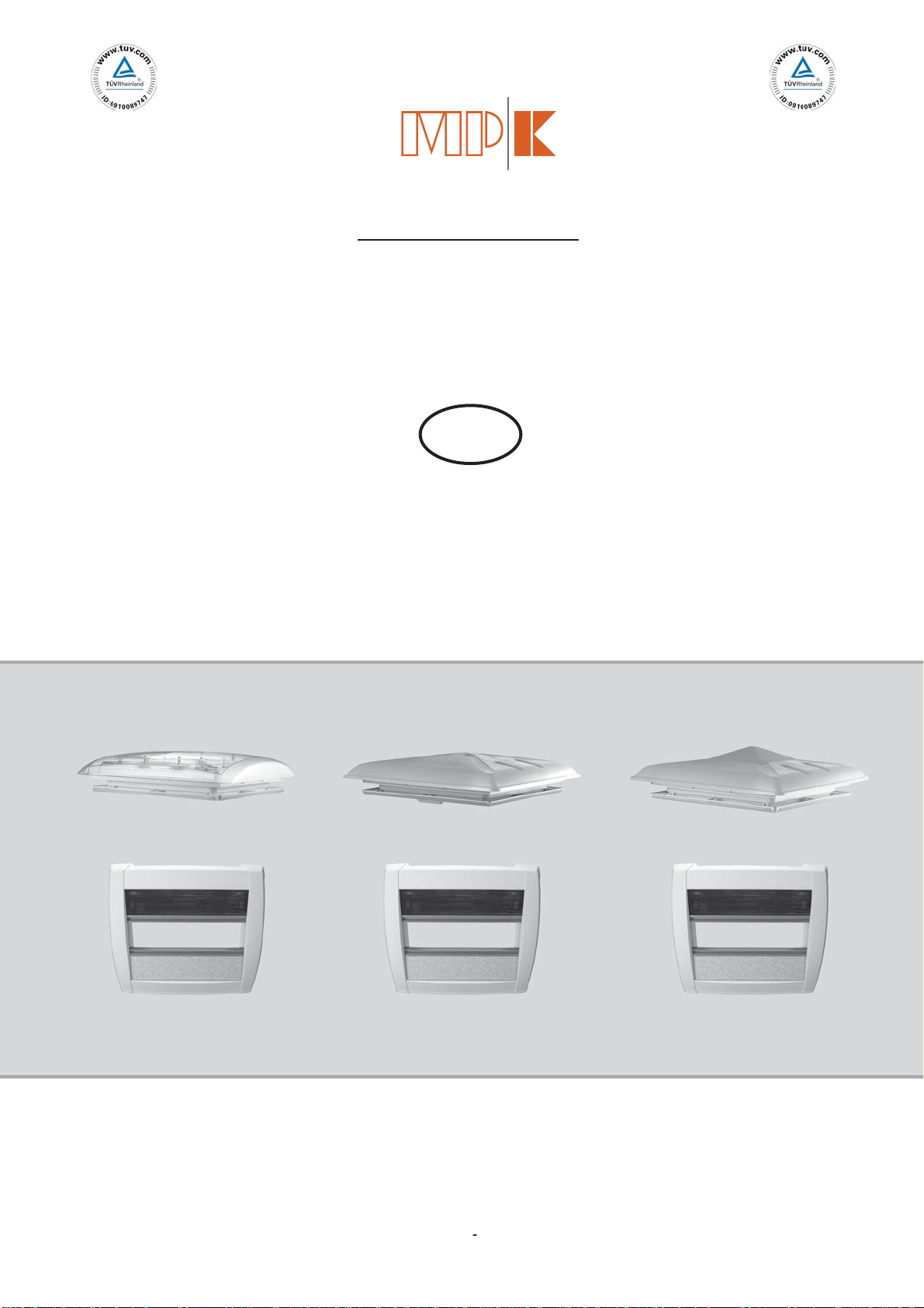
Produktbeschreibung
- Klar- bzw. Milchglashauben mit Dauerlüftung
- Teleskopaussteller, in vier Richtungen kippbar mit Verriegelung
- verdeckte Verschraubung
- Innenrahmen mit Doppelplissee (mit/ ohne Verdunklung)
- ECE R43 Zulassung für Wohnwagen und Reisemobile
(Detaillierte Informationen auf Anfrage.)
Technische Informationen
Verwenden Sie zum Reinigen der Haube ausschließlich klares
Wasser.ScharfeReinigungsmittel könnendenKunststoffangreifen
und brüchig machen. Verwenden Sie einen weichen Schwamm
um die Oberfläche nicht zu verkratzen.
Zum Reinigen läßt sich die komplette Einheit der Hauben mit
Ausstellern mittels vier Schrauben vom Rahmen lösen. (Seit Mai
2010 Torx TK 10) (Abbildung 12)
Achten Sie beim Wiedereinsetzen der Haube darauf, die Schrau-
ben richtig anzuziehen. Überdrehen Sie die Schrauben nicht im
Kunststoff. Verwenden Sie ausschließlich die Originalschrau-
ben.
Lösen Sie niemals die Verbindungsschrauben zwischen Aus-
steller und Hauben. (Abbildung 12) Diese dürfen nur von einer
Fachwerkstatt mittels speziellem Drehmomentschraubendreher
festgezogen werden.
Zum Reinigen kann der Innenrahmen mit den Plissees abge-
nommen werden. Verfahren Sie in umgekehrter Reihenfolge wie
bei der Montage. Lösen Sie die Schrauben von Hand mit einem
Schraubendreher.
Reinigung

6
Technische Informationen
Lieferbare Ausführungen:
Modell 44P (milchige Haube)
weiß Verd. Netz Dachdicke Lüftung Gewicht
440VPW-D X X 24 - 56 mm 95 cm² 3090 g
441VPW-D X X 42 - 70 mm 95 cm² 3190 g
Modell 4400P (transparente Haube)
weiß Verd, Netz Dachdicke Lüftung Gewicht
4400VPW-D X X 24 - 56 mm 95 cm² 3090 g
4410VPW-D X X 42 - 70 mm 95 cm² 3190 g
Lieferbare Ausführungen:
Modell 46P (milchige Haube)
weiß Verd. Netz Dachdicke Lüftung Gewicht
460VPW-D X X 24 - 56 mm 150 cm² 3135 g
461VPW-D X X 42 - 70 mm 150 cm² 3235 g
460VPW-D-3 X X 24 - 56 mm 30 cm² 3135 g
461VPW-D-3 X X 42 - 70 mm 30 cm² 3235 g
Modell 4600P (transparente Haube)
weiß Rollo Netz Dachdicke Lüftung Gewicht
4600VPW-D X X 24 - 56 mm 150 cm² 3135 g
4610VPW-D X X 42 - 70 mm 150 cm² 3235 g
4600VPW-D-3 X X 24 - 56 mm 30 cm² 3135 g
4610VPW-D-3 X X 42 - 70 mm 30 cm² 3235 g
Lieferbare Ausführungen:
Modell 4751P - klare Haube
weiß Verd. Netz Dachdicke Lüftung Gewicht
4751VPW X X 24 - 56 mm 150 cm² 3645 g
4761VPW X X 42 - 70 mm 150 cm² 3745 g
Modell 4753P - Rauchglashaube
weiß Verd. Netz Dachdicke Lüftung Gewicht
4753VPW X X 24 - 56 mm 150 cm² 3645 g
4763VPW X X 42 - 70 mm 150 cm² 3745 g
g Gewicht
95 cm²
2 - 70 mm 95 c
e Haube)
Verd, Net
4400VPW-D X
4410VPW-
NICHT MEHR LIEFERBAR

7
Ersatzteilübersicht
5
6
4
3
1
2
3
4a
Rahmenfarbe:
Nr. Ersatzteilbezeichnung
weiß
grau
Ersatzhauben, Verriegelungen:
1a Ersatzhaube Modell 4751P/ 4753P
klar - 150 cm² Lüftung 4751.52VW 4751.52VG
Rauchglas - 150 cm² Lüftung 4753.52VW 4753.52VG
1b Ersatzhaube Modell 46P / 4600P
opac - 150 cm² Lüftung 460.52VW 460.52VG
opac - 30 cm² Lüftung 460.52VW-3 460.52VG-3
transparent -150 cm² Lüftung 4600.52VW 4600.52VG
transparent - 30 cm² Lüftung 4600.52VW-3 4600.52VG-3
8
Rahmenfarbe:
Nr. Ersatzteilbezeichnung
weiß
grau
Ersatzhauben, Verriegelungen:
1c Ersatzhaube Modell 44P / 4400P
opac - 95 cm² Lüftung
transparent - 95 cm² Lüftung
5 Verriegelung 1 Satz im PE-Beutel 420.99S 420.99S
6 Schrauben für Aussteller 8000.4 8000.4
Ersatzrahmen innen/ außen + Zubehör
2 Oberrahmen für Mod. 44P - 4751P/ 4753P
für Dachdicke 24 - 56 mm 420.21W 420.21G
für Dachdicke 42 - 70 mm 421.21W -------------
3 Befestigungsteile - Set 4750.99D 4750.99D
(4 Eckwinkel/ 4 Seitenwinkel/ 4 KU-Schrauben)
4 Unterrahmen kpl. 4750.22PW -------------
Unterrahmen - Nachrüst-Set 4750.22PW-K --------------
4a Seitl. Abdeckungen zu Innenrahmen 4750.1W -------------
Ersatzteilübersicht
Nicht mehr lieferbar
(Ersatzhauben siehe Mod. 46P/
4600P/ 4751P/ 4753P)
1
Fitting and Operating Instructions
GB
Rooflight VisionVent M pro - Model 4751P/ 4753P
Special Models 44P/ 4400P, 46P/ 4600P
Issue June 2013
Metall- und Plastikverarbeitungs- GmbH & Co. KG Kierspe
Internet: www.mpk-kierspe.de
We reserve the richt to change technical
specifications without notice. E&OE
ISO 9001:2008
Cert.-No. 01 100 89747 ISO 14001:2004
Cert.-No. 01 104 069609
2
We only recommend installation by authorised dealers.
Please read these instructions carefully before fitting and operating the roof-
lights.
Illustration
1 23
4 5 6
7 8 9
standard
screw
hole
plastic
screw hole
Important: We cannot be held responsible for incorrect fitting, handling or operation.
Any product faults relating to the production and materials used should be noticed to us via
an authorised dealer immediately.
10 11 12
wrongwrong
wrong
wrong wrong
3
Fitting Instructions
Warning!
Fitting position
Aperture size
Roof thickness
Fitting direction
Fixing screws
- Upper frame
- Inner frame
Sealing
Fitting
Never stand on the dome of the rooflight!
(See picture 1)
Choose a fitting position that will not interfere with other roof
mounted components (e.g. roof-racks/antenna’s etc.) and avoid
internally installed electrical cables and furniture, which could
impede the correct operation of the rooflight.
The rooflight should only be fitted to a flat roof surface, both in-
ternally and externally.
400x400 mm (see technical data page 5)
Ensure the correct rooflight is selected for the roof thickness (for
available size options see technical data page 6).
Rooflights must only be fitted with the operating handles facing
the front and rear of the vehicle, not across the vehicle.
Pan 3,5 mm/head according to DIN ISO 7049 (DIN 7981)
Screwsize-Whenfully tightened the screw should enter theouter
frame about 10 mm.
Screwlengthforfitting ofinnerframe13mm(or plastic screws forbighole)
Do not use countersunk screws as they will damage the rooflight
frame (see picture 4).
Use only long term flexible sealant, suitable for external use, (not
supplied), and also suitable for the material of the upper frame.
Consult your sealant supplier.
Separate the inner and outer frames and fit the outer frame to
the outside of the roof aperture onto a bed of sealant, with the
operating handles facing front and rear of the vehicle.
Place over the screw holes on the inside of the frame, the 8
fixing brackets; four in each corner, four in the centre of each
side. Secure with screws (see picture 2). Screws not supplied.
Attention: Do not over-tighten the screws, stop as soon as the
brackets start to distort. (See picture 3).
Max. Torque 0.5 Nm
To fit the inner frame, gently pull out the pointed ends of the cover
profiles to release them and reveal the fixing points. (See picture 5).
There are two fixing holes in each corner of the frame, for two
fixing options (See picture 6 - 7).
It is recommended that the inner frame is fitted with the blinds to
the side of the vehicle, opposing the operating handles..
4
Fitting Instructions
Fitting
Instruction for use
Free-air-flow
Before driving
The four large holes are used to fit the frame to the inner lining
panel only, where there is no supporting timber frame, using the
large plastic screws supplied. Offer up the inner frame into the
outer frame and mark the central position of the large holes. Drill
holes for the screws and secure the frame to the roof with the
plastic screws. Tighten by hand, do not over-tighten.
(See pictures 8 - 9)
The four small holes are used to fit the frame to the roof when
there is a timber support under the roof lining, using pan head
screws (not supplied - see page 2). Make sure the timber support
is large enough and under the small fixing holes. (See picture 7)
Offer up the inner frame into the outer frame. Secure the frame
to the roof by fixing the screws directly into the timber support.
Tighten by hand, do not over-tighten. (See picture 8-9)
Attention: Make sure that the outer panel is not damaged by
drilling through (max drill depth 5mm) or using screws that are
too long.
Refit the inner frame covers by locating the securing lugs and
keeping the covers parallel against the roof whilst sliding them
carefully onto the frame, ‘clicking’ back into position, without
distorting. (See picture 9)
The rooflight can be opened fully by the handles, or in four diffe-
rent directions, so that the dome can be angled against driving
weather conditions.
The flynet and the blind can be operated together or separately.
To open the rooflight dome both have to be opened.
When closed there is a free airflow through the rooflight, which
must be kept free at all times (see technical data page 5-7)
IMPORTANT:All rooflights must be locked down before traveling.
Flynetsandblindsmustbe locked in the fully openpositionagainst
the frame.(See picture 10-11)
Make sure the flynet and the blind are in open position to avoid
damage and noise by airflow.
Operation Instruction

5
Care Instructions
Technical Data:
Aperture: 400 x 400 mm
Corner radius: 25 mm
Size dome: 560 x 560 mm
Height over roof model 44P/ 4400P: 117 mm
model 46P/ 4600P: 92 mm
model 4751P/ 4753P: 96 mm
Free-air-flow: Please refer to model options
Outer frame material: Polypropylene
Dome material 4751P/4753P PC/ PMMA + SAN
Other models: Polypropylene
Product description
- Clear or opaque domes with free airflow
- Spring assisted mechanism, can be tipped in 4 directions, with locks
- concealed fixing screws
- Inner frame with pleated flynet + blind (optional flynet only)
- ECE R43 Whole Vehicle Type Approved
(Please ask for further details.)
Technical Information
The rooflight should only be washed by hand, using a sponge
with plenty of clean water to avoid scratching. Caustic detergents
and solvents may attack the plastic and make it brittle or disinte-
grate.
For easier cleaning of the dome it can be removed from the frame
byreleasingthefourscrews holding the handle arms(modelsfrom
May 2010, Torx TK10 screws). (See picture 12)
Make sure that only the original screws are used when replacing
the dome and that they enter the thread in the plastic correctly.
Do not over-tighten.
Neverremovethescrewsholdingthedome and the handles toge-
ther (see picture 12). These are secured by a torque screwdriver
and should only be handled by an approved dealers.
To remove the inner frame for cleaning, with the flynet and blind
attached, follow the reverse of the fitting instructions; removing
covers and screws.
Cleaning

6
Technical Information
Model options:
Model 44P (opaque dome)
white blind net roof thickness air-flow weight
440VPW-D X X 24 - 56 mm 95 cm² 3090 g
441VPW-D X X 42 - 70 mm 95 cm² 3190 g
Model 4400P (clear dome)
white blind net roof thickness air-flow weight
4400VPW-D X X 24 - 56 mm 95 cm² 3090 g
4410VPW-D X X 42 - 70 mm 95 cm² 3190 g
Model options:
Model 46P (opaque dome)
white blind net roof thickness air-flow weight
460VPW-D X X 24 - 56 mm 150 cm² 3135 g
461VPW-D X X 42 - 70 mm 150 cm² 3235 g
460VPW-D-3 X X 24 - 56 mm 30 cm² 3135 g
461VPW-D-3 X X 42 - 70 mm 30 cm² 3235 g
Model 4600P(clear dome)
white blind net roof thickness air-flow weight
4600VPW-D X X 24 - 56 mm 150 cm² 3135 g
4610VPW-D X X 42 - 70 mm 150 cm² 3235 g
4600VPW-D-3 X X 24 - 56 mm 30 cm² 3135 g
4610VPW-D-3 X X 42 - 70 mm 30 cm² 3235 g
Model options:
Model 4751P - clear dome
white blind net roof thickness air-flow weight
4751VPW X X 24 - 56 mm 150 cm² 3645 g
4761VPW X X 42 - 70 mm 150 cm² 3745 g
Model 4753P - smoked dome
white blind net roof thickness air-flow weight
4753VPW X X 24 - 56 mm 150 cm² 3645 g
4763VPW X X 42 - 70 mm 150 cm² 3745 g
w weight
g
m 95 cm²
42 - 70 mm 95 cm
blind net
4400VPW-D X
4410VPW-
OUT OF PRODUCTION

7
Spare parts
Colour frame:
No. Spare parts
white
grey
Replacement dome, locks
1a Replacement dome model 4751P/ 4753P
clear - 150 cm² air-flow 4751.52VW 4751.52VG
smoked - 150 cm² air-flow 4753.52VW 4753.52VG
1b Replacement dome model 46P / 4600P
opaque - 150 cm² air-flow 460.52VW 460.52VG
opaque - 30 cm² air-flow 460.52VW-3 460.52VG-3
clear -150 cm² air-flow 4600.52VW 4600.52VG
clear - 30 cm² air-flow 4600.52VW-3 4600.52VG-3
5
6
4
3
1
2
3
4a
8
Colour frame:
No. Spare parts
white
grey
Replacement dome, locks
1c Replacement dome model 44P / 4400P
opaque - 95 cm² air-flow
clear - 95 cm² air-flow
5 Locks; 1 set supplied in polybag with hanger 420.99S 420.99S
6 Torx screws for handles 8000.4 8000.4
Replacement frame, fixing parts:
2 Outer frame for mod. 44P - 4751P/ 4753P
for roof thickness 24 - 56 mm 420.21W 420.21G
for roof thickness 42 - 70 mm 421.21W -------------
3 Fixing kit - incl. 4 corner brackets, 4 side brackets 4750.99D 4750.99D
and 4 plastic screws
4 Inner frame, compl. with flynet/ blind 4750.22PW -------------
Inner frame, upgrade kit with fixing brackets 4750.22PW-K -------------
4a Side covers for inner frame 4750.1W -------------
Spare parts
Out of production
(Replacement domes see mod. 46P/
4600P/ 4751P/ 4753P)
Other manuals for VisionVent M pro
2
This manual suits for next models
6
Table of contents
Languages:
Other MPK Lighting Equipment manuals


Popular Lighting Equipment manuals by other brands

Chauvet
Chauvet Q-WASH 560Z-LED Quick reference guide

MediaShop
MediaShop Disk Lights STONE Instructions for use

ETC
ETC CE Source Four user manual

Dentsply Sirona
Dentsply Sirona SmartLite Pro Instructions for use
Red Arrow
Red Arrow POLO 15W LED installation instructions

GO PERFORMANCE
GO PERFORMANCE L3 Series Mounting instruction


