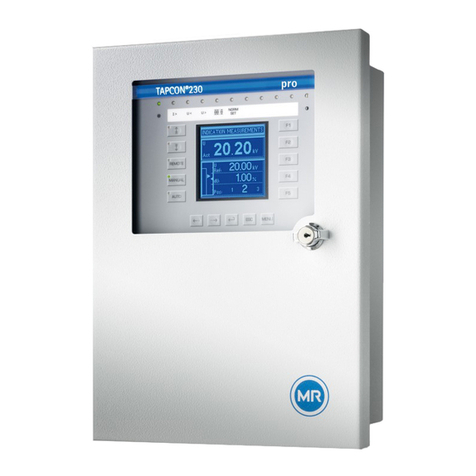
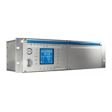
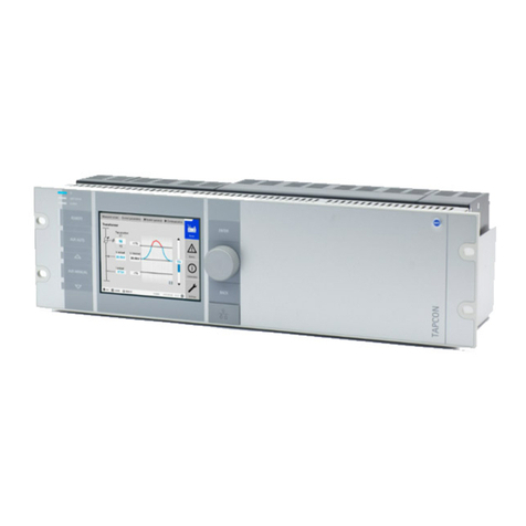
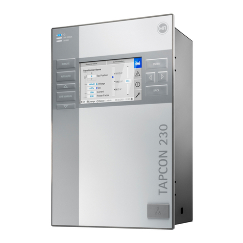
MR TAPCON 250 Owner's manual

Voltage Controller
TAPCON® 250
Supplement
2060168/02 EN . Adapter Panel TC250-67_04

© All rights reserved by Maschinenfabrik Reinhausen
Dissemination and reproduction of this document and use and disclosure of its content are strictly prohibited
unless expressly permitted.
Infringements will result in liability for compensation. All rights reserved in the event of the granting of patents,
utility models or designs.
The product may have been altered since this document was published.
We reserve the right to change the technical data, design and scope of supply.
Generally the information provided and agreements made when processing the individual quotations and orders
are binding.
The original operating instructions were written in German.

Table of contents
Maschinenfabrik Reinhausen 2014 32060168/02 EN TAPCON® 250
Table of contents
1Introduction ......................................................................................................................... 4
1.1 Manufacturer ....................................................................................................................................... 4
1.2 Subject to change without notice......................................................................................................... 4
1.3 Completeness...................................................................................................................................... 4
1.4 Supporting documents......................................................................................................................... 4
1.5 Safekeeping......................................................................................................................................... 5
2Safety ................................................................................................................................... 6
2.1 General safety information .................................................................................................................. 6
2.2 Appropriate use ................................................................................................................................... 6
2.3 Inappropriate use................................................................................................................................. 6
2.4 Personnel qualification ........................................................................................................................ 7
2.5 Operator's duty of care ........................................................................................................................ 7
3Product description ............................................................................................................ 8
4Mounting .............................................................................................................................. 9
4.1 Installing the adapter panel ................................................................................................................. 9
4.2 Cable recommendation ....................................................................................................................... 9
4.3 Electromagnetic compatibility ............................................................................................................ 10
4.4 Connecting the adapter panel ........................................................................................................... 10
5Technical data ................................................................................................................... 16

1 Introduction
Maschinenfabrik Reinhausen 20144 2060168/02 ENTAPCON® 250
Introduction
This technical file contains detailed descriptions on the safe and proper in-
stallation, connection, commissioning and monitoring of the product.
It also includes safety instructions and general information about the prod-
uct.
This technical file is intended solely for specially trained and authorized per-
sonnel.
Manufacturer
The product is manufactured by:
Reinhausen Manufacturing Inc.
2549 North 9th Avenue
Humboldt, Tennessee 38343, USA
Tel.: (+1) 731/784-7681
Fax: (+1) 731/784-7682
E-mail: [email protected]
Further information on the product and copies of this technical file are avail-
able from the address listed above or at www.tapcon250.com.
Subject to change without notice
The information contained in this technical file comprises the technical speci-
fications approved at the time of printing. Significant modifications will be in-
cluded in a new edition of the technical file.
The document number and version number of this technical file are shown in
the footer.
Completeness
This technical file is incomplete without the supporting documentation.
Supporting documents
The following documents apply to this product:
▪ Operating instructions
▪ Connection diagrams
Also observe generally valid legislation, standards, guidelines and specifica-
tions on accident prevention and environmental protection in the respective
country of use.
1
1.1
1.2
1.3
1.4

1 Introduction
Maschinenfabrik Reinhausen 2014 52060168/02 EN TAPCON® 250
Safekeeping
This technical file and all supporting documents must be kept ready at hand
and accessible for future use at all times.
1.5

2 Safety
Maschinenfabrik Reinhausen 20146 2060168/02 ENTAPCON® 250
Safety
General safety information
The technical file contains detailed descriptions on the safe and proper in-
stallation, connection, commissioning and monitoring of the product.
▪ Read this technical file through carefully to familiarize yourself with the
product.
▪ Particular attention should be paid to the information given in this chap-
ter.
Appropriate use
The product and associated equipment and special tools supplied with it
comply with the relevant legislation, regulations and standards, particularly
health and safety requirements, applicable at the time of delivery.
If used as intended and in compliance with the specified requirements and
conditions in this technical file as well as the warning notices in this technical
file and attached to the product, then the product does not present any haz-
ards to people, property or the environment. This applies throughout the
product's entire life, from delivery through installation and operation to disas-
sembly and disposal.
The operational quality assurance system ensures a consistently high quality
standard, particularly in regard to the observance of health and safety re-
quirements.
The following is considered appropriate use
▪ The product must be operated in accordance with this technical file and
the agreed delivery conditions and technical data
▪ The equipment and special tools supplied must be used solely for the in-
tended purpose and in accordance with the specifications of this techni-
cal file
Inappropriate use
Use is considered to be inappropriate if the product is used other than as de-
scribed in the Appropriate use section. Please also note the following:
▪ Risk of explosion and fire from highly flammable or explosive gases, va-
pors, or dusts. Do not operate product in areas at risk of explosion.
▪ Unauthorized or inappropriate changes to the product may lead to per-
sonal injury, material damage, and operational faults. Only modify prod-
uct following discussion with Maschinenfabrik Reinhausen GmbH.
2
2.1
2.2
2.3
2 Safety
Maschinenfabrik Reinhausen 2014 72060168/02 EN TAPCON® 250
Personnel qualification
The product is designed solely for use in electrical energy systems and facili-
ties operated by appropriately trained staff. This staff comprises people who
are familiar with the installation, assembly, commissioning and operation of
such products.
Operator's duty of care
To prevent accidents, disruptions and damage as well as unacceptable ad-
verse effects on the environment, those responsible for transport, installa-
tion, operation, maintenance and disposal of the product or parts of the prod-
uct must ensure the following:
▪ All warning and hazard notices are complied with.
▪ Personnel are instructed regularly in all relevant aspects of operational
safety, the operating instructions and particularly the safety instructions
contained therein.
▪ Regulations and operating instructions for safe working as well as the
relevant instructions for staff procedures in the case of accidents and
fires are kept on hand at all times and are displayed in the workplace
where applicable.
▪ The product is only used when in a sound operational condition and
safety equipment in particular is checked regularly for operational relia-
bility.
▪ Only replacement parts, lubricants and auxiliary materials which are au-
thorized by the manufacturer are used.
▪ The specified operating conditions and requirements of the installation
location are complied with.
▪ All necessary devices and personal protective equipment for the specific
activity are made available.
▪ The prescribed maintenance intervals and the relevant regulations are
complied with.
▪ Installation, electrical connection and commissioning of the product may
only be carried out by qualified and trained personnel in accordance
with this technical file.
▪ The operator must ensure appropriate use of the product.
2.4
2.5

3 Product description
Maschinenfabrik Reinhausen 20148 2060168/02 ENTAPCON® 250
Product description
The TC250-67 adapter panel allows installation of the TAPCON® 250 in a
cutout with dimensions of 5-7/8" x 15-1/8" (162 x 419 mm). This makes it
possible to use a TAPCON® 250 to replace existing voltage regulators of the
following types:
▪ Westinghouse SVC
▪ Westinghouse SVR
▪ Beckwith M-0067E
▪ Beckwith M-2067B
All required connections are present on the back of the adapter panel in the
form of a terminal block. The adapter panel contains a replaceable fuse. A
spare fuse can be found in the fuse holder.
WARNING Fire hazard
Risk of fatal injury and damage to the device and system peripherals due to
the use of incorrect fuses.
► Only use fuses of the following type: Article number 312.300, manufac-
tured by LITTLEFUSE, 250 V AC/0.3 A.
3

4 Mounting
Maschinenfabrik Reinhausen 2014 92060168/02 EN TAPCON® 250
Mounting
This chapter describes how to correctly mount and connect the device. Note
the connection diagrams provided.
WARNING Electric shock
Risk of fatal injury due to electrical voltage.
► De-energize the device and system peripherals and lock them to pre-
vent them from being switched back on.
► Do so by short-circuiting the current transformer; do not idle the current
transformer.
NOTICE
Electrostatic discharge
Damage to the device due to electrostatic discharge.
► Take precautionary measures to prevent the build-up of electrostatic
charges on work surfaces and personnel.
Installing the adapter panel
Proceed as follows to assemble the TAPCON® 250 voltage regulator with
the TC250-67 adapter panel:
1. Fasten the voltage regulator on the rear side of the adapter panel using
the 4 screws provided.
2. Insert both plug terminals into connection P2 on the bottom of the volt-
age regulator.
3. Install the adapter panel with voltage regulator into a control cabinet or
appropriate mounting point.
ðThe adapter panel has been installed.
Cable recommendation
Please note the following recommendation from Maschinenfabrik Reinhau-
sen when wiring the device.
Excessive line capacitance can prevent the relay contacts from breaking the
contact current. In control circuits operated with alternating current, take into
account the effect of the line capacitance of long control lines on the func-
tion of the relay contacts.
Conductor cross-section 16...22 AWG (0.33...1.3 mm²)
Fastening Cable shoe (e.g. TYCO/AMP 36150)
Max. permissible torque 9.0 lb·in (1.1 Nm)
Table 1: Cable recommendation
4
4.1
4.2

4 Mounting
Maschinenfabrik Reinhausen 201410 2060168/02 ENTAPCON® 250
Electromagnetic compatibility
The device has been developed in accordance with applicable EMC stan-
dards. The following points must be noted in order to maintain the EMC
standards.
▪ Ground the TAPCON® 250 using the grounding screw on the housing.
▪ Route signal lines in a shielded cable.
▪ Follow the notes in the associated operating instructions regarding the
connection of the TAPCON® 250.
Connecting the adapter panel
WARNING Electric shock
Risk of fatal injury due to connection mistakes
► Ground the device using the grounding screw on the housing.
► Pay attention to the phase difference of the secondary terminals for the
current transformer and voltage transformer.
► Connect the output relays correctly to the motor-drive unit.
4.3
4.4

4 Mounting
Maschinenfabrik Reinhausen 2014 112060168/02 EN TAPCON® 250
Proceed as follows to connect the adapter panel:
► Connect the adapter panel with mounted TAPCON® 250 in accordance
with the following connection diagram and in accordance with the asso-
ciated motor-drive unit.
Figure 1: Connecting the adapter panel

4 Mounting
Maschinenfabrik Reinhausen 201412 2060168/02 ENTAPCON® 250
Figure 2: Connection diagram for the adapter panel
Motor voltage can be either 120 V or 240 V from phase to neutral conductor
or 240 V from phase to phase.
The neutral conductor for the current transformer and voltage transformer
must be grounded outside the voltage regulator.
We recommend connecting the NEUTRAL (TB1.3) and the neutral conduc-
tor for the motor.
Supplying the device using auxiliary voltage
Alternatively, you can supply the TAPCON® 250 via an auxiliary voltage
source (12 V DC, 1 A) to ensure operation even when the transformer is
switched off. Follow the notes in this regard in the associated operating in-
structions for the TAPCON® 250.

4 Mounting
Maschinenfabrik Reinhausen 2014 132060168/02 EN TAPCON® 250
Connection TB1.1, voltage input
Input for voltage measurement and supplying the TAPCON® 250. Permissi-
ble voltage range of 85...140 V AC. The power consumption of the
TAPCON® 250 is 6...12 VA (depending on the product version). The voltage
is in reference to the neutral conductor (TB1.3).
Connection TB1.2, load current (return conductor)
Connection for the current transformer return conductor.
Connection TB1.3, neutral
Return conductor for the voltage input (TB1.1) and the 12 V DC supply volt-
age (TB1.13).
If you connect the voltage transformer to measure voltage between two
phases on connections TB1:1 and TB1:3, you need to remove the line be-
tween P2.23 and TB1:3 on contact TB1:3 and connect it to the motor-drive
unit's neutral point.
Connection TB1.4, load current (feeder conductor)
Input for load current measurement. Permissible current range 0...420 mA
(200 mA continuous). Load current measurement is used for the "line drop
compensation (LDC)" function and for measured value calculation.
Connection TB1.5, 12 V DC auxiliary voltage output
Auxiliary voltage output (12 V DC) for freely configurable inputs. You can re-
move the jumper between TB1.5 and TB1.6 to switch the state of input GPI2
via an external selector switch.
NOTICE
Damage to voltage regulator
Damage to voltage regulator due to incorrect connection.
► Do not connect connections TB1.5 and TB1.6 to the current transform-
er.
Connection TB1.6, input GPI2 (freely configurable)
Freely configurable input GPI2 for receiving the auxiliary voltage (12 V DC).
You can remove the jumper between TB1.5 and TB1.6 to switch the state of
input GPI2 via an external selector switch. Follow the operating instructions
for the TAPCON® 250 to configure input GPI2.
Connection TB1.7, tap changer raise output
This switched output connects the raise winding of the motor-drive unit to the
source of the motor supply (connection TB1.8). The maximum switching ca-
pacity for the output is 6 A at 120/240 V AC.

4 Mounting
Maschinenfabrik Reinhausen 201414 2060168/02 ENTAPCON® 250
Connection TB1.8, input for supplying the motor-drive unit
Connection for supplying the motor-drive unit. Maximum permissible voltage
of 240 V AC.
Connection TB1.8 is connected to the P2.26 Manual/Auto connection of the
TAPCON® 250. As soon as voltage is present at connection TB1.8, the reg-
ulator switches to Auto mode. Remove the jumper between TB1.8 and
P2.26 if you want to use the P2.26 Manual/Auto input with an alternating
voltage source or as a pulsed input.
Connection TB1.9, tap changer lower output
This switched output connects the lower winding of the motor-drive unit to
the source of the motor supply (connection TB1.8). The maximum switching
capacity for the output is 6 A at 120/240 V AC.
Connections TB1.10 (GPI3), TB1.11 (GPI4), TB1.12 (GPI1)
You can link these inputs to various voltage regulator functions. Follow the
operating instructions for the TAPCON® 250 in this regard. The inputs are
activated with 12 V DC from connection TB1.5 or TB1.13.
Connection TB1.13, 12 V DC auxiliary voltage output
Output of an unregulated internal DC voltage source with NEUTRAL refer-
ence potential (TB1.3). The DC voltage source can be used to supply the
digital inputs connected via an external relay. Depending on the voltage at
TB1.1 and the connected load, the output voltage is 10...18 V DC. The maxi-
mum current is 100 mA; the output is not protected by a fuse in the
TAPCON® 250.
Connections TB2.14 and TB2.15, raise/lower tap-change operation in
manual mode
These inputs are used for connecting external "raise" or "lower" switches.
These inputs allow you to increase or decrease the voltage in manual mode.
If you correctly connect the connections for raise/lower tap changer output
(TB1.7, TB1.9) and the operations counter connection (TB2.20), manual tap-
change operations are detected by the TAPCON® 250 using external
switches.
Connections TB2.16 and TB2.17, alarm signal self-test
This pair of connections is a relay for an alarm signal (6 A at 120 V AC) that
operates in accordance with the closed-circuit principle. The relay closes in
the event of a fault in the voltage supply or the microcontroller.

4 Mounting
Maschinenfabrik Reinhausen 2014 152060168/02 EN TAPCON® 250
Connections TB2.18 and TB2.19, freely configurable alarm
This pair of connections is a relay for an alarm signal (6 A at 120 V AC) that
operates in accordance with the open-circuit principle. The relay closes if the
requirements for the alarm configured in the voltage regulator are met. Fol-
low the operating instructions for the TAPCON® 250 in this regard.
Connection TB2.20, operations counter
Digital input for recording the number of tap-change operations. The opera-
tions counter is increased each time connection TB2.20 is set to NEUTRAL
(TB1.3). The input is level-dependent. Ensure that any auxiliary voltage is re-
moved from the operations counter connections before installing the
TC250-6704 adapter panel together with the TAPCON® 250.
NOTICE
Damage to voltage regulator
Damage to voltage regulator due to incorrect connection.
► Do not attach any voltage sources (12 V DC or 120 V AC) to connec-
tion TB2.20.
Connection TB 2.21, Remote input
This input is used for connecting an external remote switch. This switch lets
you activate the voltage regulator's Remote operating mode (e.g. for control
via a control system protocol). The Remote operating mode is active if you
provide 120 V AC.

5 Technical data
Maschinenfabrik Reinhausen 201416 2060168/02 ENTAPCON® 250
Technical data
Figure 3: Front view and rear view
5

5 Technical data
Maschinenfabrik Reinhausen 2014 172060168/02 EN TAPCON® 250
Figure 4: Side view


MR worldwide
Australia
Reinhausen Australia Pty. Ltd.
17/20-22 St Albans Road
Kingsgrove NSW 2208
Phone: +61 2 9502 2202
Fax: +61 2 9502 2224
E-Mail: [email protected]
Brazil
MR do Brasil Indústria Mecánica Ltda.
Av. Elias Yazbek, 465
CEP: 06803-000
Embu - São Paulo
Phone: +55 11 4785 2150
Fax: +55 11 4785 2185
E-Mail: [email protected]
Canada
Reinhausen Canada Inc.
3755, rue Java, Suite 180
Brossard, Québec J4Y 0E4
Phone: +1 514 370 5377
Fax: +1 450 659 3092
E-Mail: [email protected]
India
Easun-MR Tap Changers Ltd.
612, CTH Road
Tiruninravur, Chennai 602 024
Phone: +91 44 26300883
Fax: +91 44 26390881
E-Mail: [email protected]
Indonesia
Pt. Reinhausen Indonesia
German Center, Suite 6310,
Jl. Kapt. Subijanto Dj.
BSD City, Tangerang
Phone: +62 21 5315-3183
Fax: +62 21 5315-3184
E-Mail: [email protected]
Iran
Iran Transfo After Sales Services Co.
Zanjan, Industrial Township No. 1 (Aliabad)
Corner of Morad Str.
Postal Code 4533144551
E-Mail: [email protected]
Italy
Reinhausen Italia S.r.l.
Via Alserio, 16
20159 Milano
Phone: +39 02 6943471
Fax: +39 02 69434766
E-Mail: [email protected]
Japan
MR Japan Corporation
German Industry Park
1-18-2 Hakusan, Midori-ku
Yokohama 226-0006
Phone: +81 45 929 5728
Fax: +81 45 929 5741
Luxembourg
Reinhausen Luxembourg S.A.
72, Rue de Prés
L-7333 Steinsel
Phone: +352 27 3347 1
Fax: +352 27 3347 99
E-Mail: [email protected]
Malaysia
Reinhausen Asia-Pacific Sdn. Bhd
Level 11 Chulan Tower
No. 3 Jalan Conlay
50450 Kuala Lumpur
Phone: +60 3 2142 6481
Fax: +60 3 2142 6422
E-Mail: [email protected]
P.R.C. (China)
MR China Ltd. (MRT)
开德贸易(上海)有限公司
中国上海浦东新区浦东南路 360 号
新上海国际大厦 4 楼 E 座
邮编: 200120
电话:+ 86 21 61634588
传真:+ 86 21 61634582
Russian Federation
OOO MR
Naberezhnaya Akademika Tupoleva
15, Bld. 2 ("Tupolev Plaza")
105005 Moscow
Phone: +7 495 980 89 67
Fax: +7 495 980 89 67
E-Mail: [email protected]
South Africa
Reinhausen South Africa (Pty) Ltd.
No. 15, Third Street, Booysens Reserve
Johannesburg
Phone: +27 11 8352077
Fax: +27 11 8353806
E-Mail: [email protected]
South Korea
Reinhausen Korea Ltd.
21st floor, Standard Chartered Bank Bldg.,
47, Chongro, Chongro-gu,
Seoul 110-702
Phone: +82 2 767 4909
Fax: +82 2 736 0049
E-Mail: [email protected]
U.S.A.
Reinhausen Manufacturing Inc.
2549 North 9th Avenue
Humboldt, TN 38343
Phone: +1 731 784 7681
Fax: +1 731 784 7682
E-Mail: [email protected]
United Arab Emirates
Reinhausen Middle East FZE
Dubai Airport Freezone, Building Phase 6
3rd floor, Office No. 6EB, 341 Dubai
Phone: +971 4 2368 451
Fax: +971 4 2368 225
Email: [email protected]
Maschinenfabrik Reinhausen GmbH
Falkensteinstrasse 8
93059 Regensburg
+49 (0)941 4090-0
+49(0)941 4090-7001
www.reinhausen.com
2060168/02 EN ▪ 06/14 ▪ F0168804
Other manuals for TAPCON 250
2
Table of contents
Other MR Controllers manuals
Popular Controllers manuals by other brands

Yisutongma Network Technology
Yisutongma Network Technology ESM-9013 instruction manual

Flowserve
Flowserve Limitorque LTQ008 User instructions

Karl Suss
Karl Suss CIC 1200 manual

Omron
Omron SYSMAC C200H-FZ001 Operation manual

Siemens
Siemens SIMATIC S5 manual

ImoLaza
ImoLaza Smart Sprinkler Controller manual