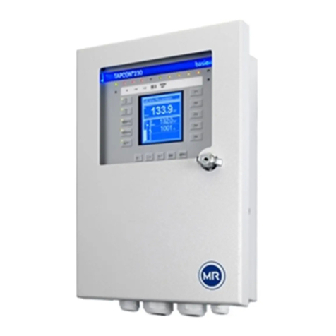
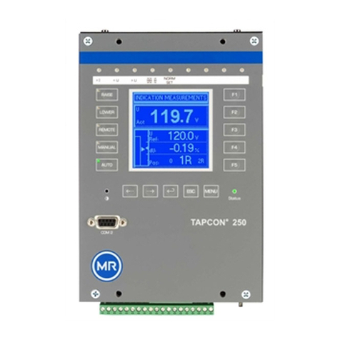
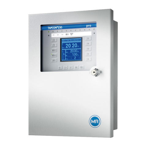
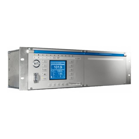
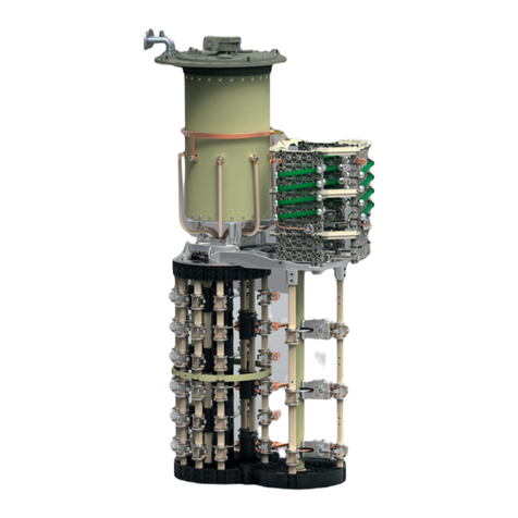
MR TAPCON 260 User manual

Voltage regulator TAPCON® 260
Operating Instructions 1801003/04
Protocol description for IEC 61850

© All rights reserved by Maschinenfabrik Reinhausen
Copying and distribution of this document and utilization and communication of its contents are strictly prohibited
unless expressly authorized.
Offenders will be held liable for the payment of damages. All rights reserved in the event of the grant of a patent,
utility model or ornamental design registration.
The product may have been modified after this document went to press.
We expressly reserve the right to make changes to the technical data, the design or the scope of delivery.
Generally, the information provided and the arrangements agreed during processing of the relevant quotations
and orders are binding.
The original operating instructions were drawn up in German.

Table of Contents
© Maschinenfabrik Reinhausen 2011 1801003/04 EN TAPCON® 260 3
Table of Contents
1Introduction .................................................................................. 9
1.1Manufacturer.............................................................................................9
1.2Subject to change without notice ..............................................................9
1.3Completeness ...........................................................................................9
1.4Supporting documents ............................................................................10
1.5Safekeeping ............................................................................................10
1.6Notation conventions ..............................................................................10
1.6.1Abbreviations used ............................................................................................. 11
1.6.2Hazard communication system........................................................................... 12
1.6.3Information system.............................................................................................. 13
2Safety .......................................................................................... 15
2.1General safety information......................................................................15
2.2Appropriate use.......................................................................................15
2.3Inappropriate use ....................................................................................16
2.4Personnel qualification............................................................................16
2.5Operator duty of care ..............................................................................16
3Product description ................................................................... 19
3.1Performance features .............................................................................21
3.2Relay of the signals via IEC 61850 .........................................................22

Table of Contents
4 TAPCON® 260 1801003/04 EN © Maschinenfabrik Reinhausen 2011
3.2.1LLN0 - Logical node............................................................................................ 22
3.2.2LPHD - Physical device ...................................................................................... 23
3.2.3LPHD - Physical device ...................................................................................... 24
3.2.4GGIO1 - IO card inputs....................................................................................... 27
3.2.5GGIO2 - UC1 card inputs ................................................................................... 28
3.2.6GGIO3 - UC2 card inputs ................................................................................... 29
3.2.7GGIO4 - UC3 card inputs (optional) ................................................................... 30
3.2.8YLTC1 - On-load tap-changer control/monitoring (optional) .............................. 32
3.2.9YPTR - Transformer (optional) ........................................................................... 33
3.3Operating modes .................................................................................... 35
3.4Scope of delivery .................................................................................... 35
3.5Hardware description.............................................................................. 36
3.5.1Internal design .................................................................................................... 37
3.5.2Communication Interfaces.................................................................................. 37
3.6Operation and indicator elements........................................................... 42
3.6.1Operating concept .............................................................................................. 43
3.6.2Description of the display ................................................................................... 44
3.6.3Description of key functions................................................................................ 46
3.6.4Description of LEDs ............................................................................................ 47
4Packaging, Transport and Storage ........................................... 49
4.1Packaging............................................................................................... 49
4.1.1Purpose .............................................................................................................. 49
4.1.2Suitability, structure and production ................................................................... 49
4.1.3Markings ............................................................................................................. 50
4.2Transportation, receipt and handling of shipments................................. 50
4.3Storage of shipments.............................................................................. 51

Table of Contents
© Maschinenfabrik Reinhausen 2011 1801003/04 EN TAPCON® 260 5
5Mounting ..................................................................................... 53
5.1Unpacking ...............................................................................................53
5.2Mounting .................................................................................................53
5.3Connection..............................................................................................54
5.3.1Cable recommendation for standard connections .............................................. 54
5.3.2Cable recommendation for optional connections ............................................... 55
5.3.3Electromagnetic compatibility ............................................................................. 55
5.3.4Connecting lines to the system periphery........................................................... 62
5.3.5Voltage regulator power supply .......................................................................... 63
5.3.6Wiring the voltage regulator................................................................................ 63
5.4Function check........................................................................................64
6Commissioning .......................................................................... 65
6.1Configuration...........................................................................................65
6.1.1Setting the language ........................................................................................... 65
6.1.2Selecting the control mode ................................................................................. 66
6.1.3Controlling remote tap position indicator with BCD signal.................................. 67
6.2Function tests..........................................................................................69
6.2.1Function tests for control functions ..................................................................... 69
6.2.2Function tests for additional functions ................................................................ 71
6.2.3Function tests for parallel operation.................................................................... 74
7Functions and settings .............................................................. 79
7.1Key lock ..................................................................................................79
7.1.1Activating key lock .............................................................................................. 79
7.1.2Deactivating key lock .......................................................................................... 79
7.2NORMset ................................................................................................80
7.2.1Entering NORMset desired value 1 .................................................................... 82

Table of Contents
6 TAPCON® 260 1801003/04 EN © Maschinenfabrik Reinhausen 2011
7.2.2Setting the primary voltage ................................................................................. 83
7.2.3Setting the secondary voltage ............................................................................ 84
7.3Parameters ............................................................................................. 85
7.3.1Setting control parameters ................................................................................. 85
7.3.2Setting desired value 1 ....................................................................................... 86
7.3.3Setting desired value 2 ....................................................................................... 87
7.3.4Setting desired value 3 ....................................................................................... 88
7.3.5Bandwidth ........................................................................................................... 89
7.3.6Setting delay time T1 .......................................................................................... 93
7.3.7Setting control response T1................................................................................ 95
7.3.8Activating/deactivating delay time T2 ................................................................. 96
7.3.9Setting delay time T2 .......................................................................................... 97
7.3.10Limit values......................................................................................................... 97
7.3.11Abnormal control response............................................................................... 107
7.3.12Compensation................................................................................................... 111
7.3.13Cross-monitoring .............................................................................................. 120
7.4Configuration ........................................................................................ 129
7.4.1Transformer data .............................................................................................. 129
7.4.2General ............................................................................................................. 138
7.4.3Parallel operation.............................................................................................. 151
7.4.4Configuring analog inputs................................................................................. 162
7.4.5LED selection.................................................................................................... 170
7.4.6Configuring transducer function........................................................................ 173
7.4.7Configuring measured value memory function (optional)................................. 179
7.4.8Communication interface SID........................................................................... 196
7.5Info........................................................................................................ 201
7.5.1Carrying out LED test ....................................................................................... 203
7.5.2Querying status................................................................................................. 204
7.5.3Resetting parameters ....................................................................................... 206
7.5.4Displaying real-time clock................................................................................. 206
7.5.5Displaying parallel operation ............................................................................ 206
7.5.6Displaying data on CAN bus............................................................................. 207
7.5.7Displaying measured value memory ................................................................ 209
Table of Contents
© Maschinenfabrik Reinhausen 2011 1801003/04 EN TAPCON® 260 7
7.5.8Displaying peak memory................................................................................... 209
7.5.9Displaying CIC1 card SCADA information........................................................ 210
7.5.10Displaying CIC2 card SCADA information........................................................ 211
7.5.11Displaying upcoming messages ....................................................................... 212
8Interface description for IEC 61850 protocol ......................... 213
8.1Physical connection ..............................................................................213
8.2Device-specific data points for TAPCON® 260 ....................................213
8.3Downloading the ICD file ......................................................................214
9Fault elimination....................................................................... 215
9.1Operating faults.....................................................................................215
9.1.1No control in AUTO mode................................................................................. 215
9.1.2Man Machine Interface ..................................................................................... 216
9.1.3Incorrect measured values................................................................................ 217
9.1.4Parallel operation faults .................................................................................... 218
9.1.5Tap position capture incorrect .......................................................................... 219
9.1.6Digital inputs ..................................................................................................... 220
9.1.7General fault ..................................................................................................... 220
9.1.8No solution ........................................................................................................ 220
9.2Event message .....................................................................................222
10Technical Data.......................................................................... 223
10.1Indicator elements.................................................................................223
10.2Electrical data .......................................................................................223
10.3Inputs and outputs ................................................................................223
10.4Dimensions and weight.........................................................................224

Table of Contents
8 TAPCON® 260 1801003/04 EN © Maschinenfabrik Reinhausen 2011
10.5Voltage and current measurement ....................................................... 225
10.6Ambient conditions ............................................................................... 225
10.7Tests..................................................................................................... 225
10.7.1Electrical safety................................................................................................. 225
10.7.2EMC tests ......................................................................................................... 226
10.7.3Environmental durability tests........................................................................... 226
11MR worldwide ........................................................................... 227

1 Introduction
© Maschinenfabrik Reinhausen 2011 1801003/04 EN TAPCON® 260 9
1 Introduction
This technical file contains detailed descriptions on the safe and proper
mounting, connection, commissioning and monitoring of the product.
It also includes safety instructions and general information about the product.
This technical file is intended solely for specially trained and authorized per-
sonnel.
1.1 Manufacturer
The product is manufactured by:
Maschinenfabrik Reinhausen GmbH
Falkensteinstraße 8
93059 Regensburg
Tel.: (+49) 9 41/40 90-0
Fax: (+49) 9 41/40 90-7001
E-Mail: sales@reinhausen.com
Further information on the product and copies of this technical file are availa-
ble from this address if required.
1.2 Subject to change without notice
The information contained in this technical file comprise the technical specifi-
cations approved at the time of printing. Significant modifications will be in-
cluded in a new edition of the technical file.
The document and version numbers of this technical file are shown in the
footer.
1.3 Completeness
This technical file is incomplete without the supporting documentation.

1 Introduction
10 TAPCON® 260 1801003/04 EN © Maschinenfabrik Reinhausen 2011
1.4 Supporting documents
The following documents apply to this product:
Operating instructions
Quick reference guide
Connection diagrams
In addition, generally applicable legal and other binding regulations of Euro-
pean and national law and the regulations for accident prevention and envi-
ronmental protection in force in the country of use must be complied with.
1.5 Safekeeping
This technical file and all supporting documents must be kept ready to hand
and accessible for future use at all times.
1.6 Notation conventions
This section contains an overview of the abbreviations, symbols and textual
emphasis used.

1 Introduction
© Maschinenfabrik Reinhausen 2011 1801003/04 EN TAPCON® 260 11
1.6.1 Abbreviations used
Abbreviation Definition
°C Degrees Celcius
A Ampere
AC Alternating Current
B Bandwidth
BCD Binary Coded Decimal
ca. circa
CAN Regulator Area Network
CIC Communication Interface Card
CPU Central Processing Unit
CT Current Transformer
DC Direct Current
DIN Deutsches Institut für Normung (German Institute for
Standardization)
DNP Distributed Network Protocol
EMC Electromagnetic compatibility
ESC Escape
Hz Hertz
I Current
IEC International Electrotechnical Commission
IP Internet Protocol
kBaud Kilobaud
kg Kilogram
kV Kilovolt
LDC Line Drop Compensation
LED Light Emitting Diode
Fiber-optic cable Fiber-optic cable
max. maximum
MB Megabyte
MR Maschinenfabrik Reinhausen
MHz Megahertz
min. minimum
mm Millimeter
ms Millisecond
N Neutral
PH Phase
Phi (φ) Phase angle
ppm Parts per million

1 Introduction
12 TAPCON® 260 1801003/04 EN © Maschinenfabrik Reinhausen 2011
Abbreviation Definition
s Second
SCADA Supervisory Control and Data Acquisition
T Time
TCP Transmission Control Protocol
V Voltage
VAct Actual voltage
VRef Reference voltage
V Volt
VT Voltage Transformer
Table 1 Abbreviations used
1.6.2 Hazard communication system
Warnings in this technical file use the following format:
DANGER!
Danger
Consequences
►Action
►Action
The following signal words are used:
Signal word Hazard level Consequence of failure to comply
Danger Immediate threat of danger Death or serious injury could occur
Warning Possible threat of danger Death or serious injury could occur
Attention Possible dangerous situation Minor or moderate injury could oc-
cur
Note Possible dangerous situation Damage to property could occur
Table 2 Signal words in warning notices

1 Introduction
© Maschinenfabrik Reinhausen 2011 1801003/04 EN TAPCON® 260 13
Pictograms warn of dangers:
Picto
gram
Meaning
Danger
Dangerous electrical voltage
Fire hazard
Danger of tipping
Table 3 Symbols used in warning notices
1.6.3 Information system
Information is designed to simplify and improve understanding of particular
procedures. In this technical file they are laid out as follows:
Important information


2 Safety
© Maschinenfabrik Reinhausen 2011 1801003/04 EN TAPCON® 260 15
2 Safety
2.1 General safety information
This technical file contains detailed descriptions on the safe and proper
mounting, connection, commissioning and monitoring of the product.
Read this technical file through carefully to familiarize yourself with the prod-
uct.
Particular attention should be paid to the information given in this chapter.
2.2 Appropriate use
The product and associated equipment and special tools supplied with it
comply with the relevant legislation, regulations and standards, particularly
health and safety requirements, applicable at the time of delivery.
If used as intended and in compliance with the specified requirements and
conditions in this technical file as well as the warning notices in this technical
file and attached to the product, then the product does not present any ha-
zards to people, property or the environment. This applies throughout the
product's full life, from delivery through installation and operation to disas-
sembly and disposal.
The operational quality assurance system ensures a consistently high quality
standard, particularly in regard to the observance of health and safety re-
quirements.
Use is considered to be appropriate if
the product is operated in accordance with this technical file and the
agreed delivery conditions and technical data, and
the associated equipment and special tools supplied with it are used
solely for the intended purpose and in accordance with the specifications
of this technical file.
the product is used only with the transformer specified in the order.

2 Safety
16 TAPCON® 260 1801003/04 EN © Maschinenfabrik Reinhausen 2011
2.3 Inappropriate use
Use is considered to be inappropriate if the product is used other than as de-
scribed in Appropriate use on page 15.
Maschinenfabrik Reinhausen does not accept liability for damage resulting
from unauthorized or inappropriate changes to the product. Inappropriate
changes to the product without consultation with Maschinenfabrik Reinhausen
can lead to personal injury, damage to property and operational disruption.
2.4 Personnel qualification
The product is designed solely for use in electrical energy systems and facili-
ties operated by appropriately trained staff. This staff comprises people who
are familiar with the installation, assembly, commissioning and operation of
such products.
2.5 Operator duty of care
To prevent accidents, disruptions and damages as well as unacceptable ad-
verse effects on the environment, those responsible for transport, installation,
operation, maintenance and disposal of the product or parts of the product
must ensure the following:
All warning and hazard notices are complied with.
Personnel are instructed regularly in all relevant aspects of operational
safety, the operating instructions and particularly the safety instructions
contained therein.
Regulations and operating instructions for safe working as well as the re-
levant instructions for staff procedures in the case of accidents and fires
are kept on hand at all times and are displayed in the workplace where
applicable.
The product is only used when in a sound operational condition and
safety equipment in particular is checked regularly for operational reliabil-
ity.
Only replacement parts, lubricants and auxiliary materials which are au-
thorized by the manufacturer are used.
The specified operating conditions and requirements of the installation
location are complied with.

2 Safety
© Maschinenfabrik Reinhausen 2011 1801003/04 EN TAPCON® 260 17
All necessary devices and personal protective equipment for each activity
are made available.
The prescribed maintenance intervals and the relevant regulations are
complied with.
Fitting, electrical connection and commissioning of the product may only
be carried out by qualified and trained personnel in accordance with this
technical file.
The operator must ensure appropriate use of the product.


3 Product description
© Maschinenfabrik Reinhausen 2011 1801003/04 EN TAPCON® 260 19
3 Product description
The voltage regulator serves to keep constant the output voltage of a trans-
former with an on-load tap-changer.
To do this, the voltage regulator compares the transformer's measured output
voltage (Vactual) with a defined reference voltage (Vreference). The difference be-
tween Vactual and Vdesired is the control deviation (dV).
If the control deviation is greater than the specified bandwidth (B%), the vol-
tage regulator emits a switching pulse after a defined delay time T1. The
switching pulse triggers an on-load tap-changer tap change which corrects the
transformer's output voltage.
The voltage regulator parameters can be optimally adjusted to the line voltage
behavior to achieve a balanced control response with a small number of
on-load tap-changer operations.
The following diagram (on page 20) shows an overview of voltage regulation.

3 Product description
20 TAPCON® 260 1801003/04 EN © Maschinenfabrik Reinhausen 2011
Figure 1 Overview of voltage regulation
Other manuals for TAPCON 260
1
Table of contents
Other MR Controllers manuals

MR
MR tapcon 230 pro User manual

MR
MR TAPCON 250 Owner's manual

MR
MR TAPCON 250 User manual

MR
MR TAPCON 230 User manual

MR
MR VACUTAP VM Series User manual

MR
MR tapcon 240 User manual

MR
MR TAPCON 260 User manual

MR
MR TAPCON 230 User manual

MR
MR TAPCON 230 basic User manual

MR
MR ECOTAP VPD CONTROL PRO User manual