MRC Mini Roller ROL-01U User manual

Mini Roller-ROL-01U
User's Manual
PLEASE READ THIS MANUAL CAREFULLYBEFORE OPERATION
3, Hagavish st. Israel 58817 Tel: 972 3 5595252, Fax: 972 35594529 [email protected]
MRC. 5.20

Index
Introduction
Cautions for Usage....................................1
Disposal and Recycling Information.....................2
Receiving and Inspection...............................2
Installation.............................................3
Overview.........................................6
Operation.......................................7
Troubleshooting..........................................8
Packing List..........................................8
Warranty Card.......................................9
.........................................1
Mini Roller Manual Mini Roller Manual
Introduction
Thank you for choosing MRC's product. This product can be used in a variety of
laboratory fields and work with different sized tubes.
Before you use the unit, please read this entire manual carefully to understand how to
operate, and maintain. Your satisfaction with the unit will be maximized because of your
increased understanding this instrument operation.
Keep this manual on-hand so it can be used by all operators of the unit. Be sure all
operators of the unit are given appropriate training before you put the unit in service.
Cautions for Usage
1. Be sure you follow any city, county, or other ordinances in your area regarding the use
of this unit.
2. Use only approved accessories. Do not modify system components. Any alternations
or modifications to your machine may be dangerous and will void your warranty.
3. Do not modify the power cord provided with the unit. If the plug does not fit an outlet,
have a proper outlet installed by a qualified electrician.
4. Please only use the enclosed power supply adaptor to supply the unit.
5. Place the unit on level and sturdy surface to avoid vibration and noise.
6. Please use the unit in specified environment.
7. DO NOT move the unit while in operation.
8. DO NOT use flammable, volatile liquids or operate this unit under hazardous
conditions.
1

2 3
Your satisfaction and safety require a complete understanding of this unit,
including its proper function and operational characteristics. Be sure operators are
given adequate training before attempting to put the unit in service.
1. Inspection: The carrier, when accepting shipment, also accept responsibility for safe
delivery and is liable for loss or damage claims. On delivery, inspect for visible exterior
damage, note and describe on the freight bill any damage found and enter your claim on
the form supplied by the carrier.
2. Inspect for concealed loss or damage on the unit itself,If any, the carrier will arrange
for official inspection to substantiate your claim. Save the shipping crate until you are sure
the unit has been delivered in good condition.
3. Return Shipment: If for any reason you must return the unit, contact your customer
service representative for authorization and supply nameplate data.
4. Accessories: Make sure that all of the accessories indicated on the packing list is
included with the unit. Carefully check all packaging before discarding. If there are any
damaged or missing items, please contact your dealer.
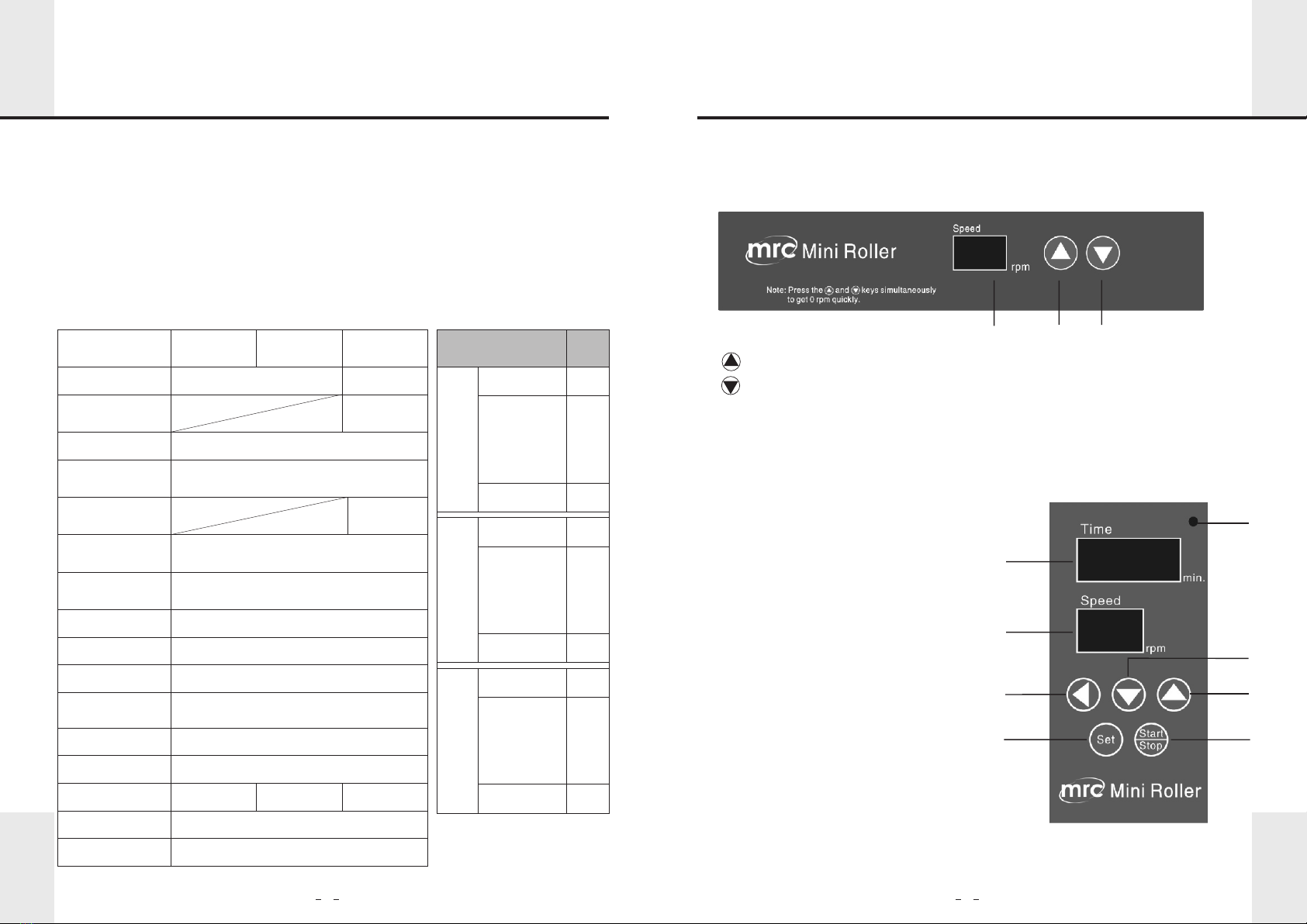
Receiving and Inspection Installation
Mini Roller Manual Mini Roller Manual
The symbol showns to the left indicates that this product shall not be
treated as household waste. In line with EU Directive 2012/19/EU
for waste electrical and electronic equipment (WEEE), this electrical
product must not be disposed of as unsorted municipal waste.
Please dispose of this product by returning it to the point of
sale or to your local municipal collection point for recycling.
Disposal and Recycling Information
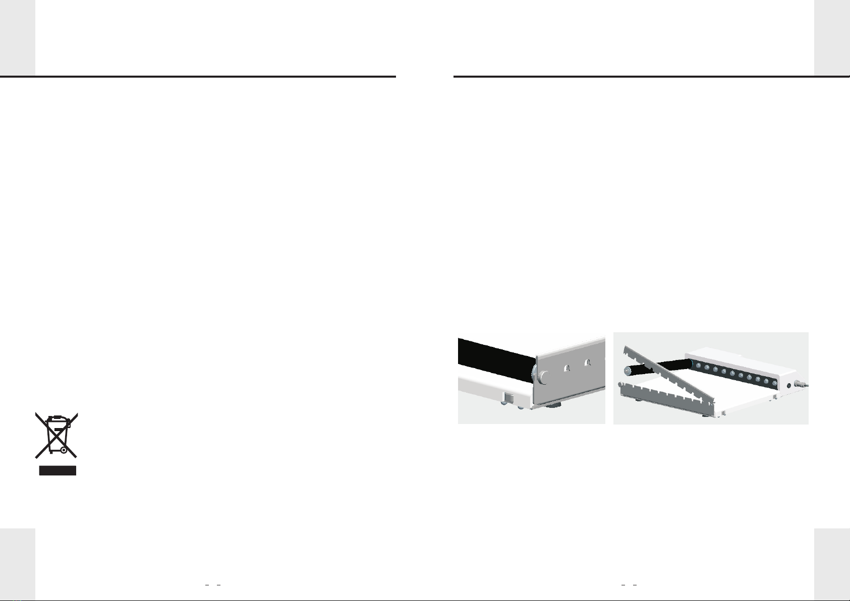
1. Control box installation (skip this step for ROL-02U series)
2. Roller bars removal and installation
Roller bars can be removed and installed for different sized tubes.
Fig-1
This unit is equipped with a separate control box (optional) Please fasten the nut
on the connection plug of control box to the unit.
NOTE: Keys on the panel of the unit will become invalid when control box is connected.
One control box controls one unit only.
.
2.1 Roller bars removal
Turn the knob counterclockwise to be loose on the unit end(see Fig-1) and then lift
the locking metal arm as shown in fig- 2.And remove it. Press the sheet metal to the
original position and clockwise twist the knob for fastening.
2.2 Roller bars installation
Turn the knob counterclockwise to be loose on the unit end (see Fig-1) and then
uplift the pressure sheet-metal. Aim Hexagon Hole of roller at Hexagon shaft of the
unit and press the other head into semicircle orifice. Press the sheet metal to the
knob position and clockwise twist the knob for fastening.
Fig-2
3. Rocking roller bars removing and installation
3.1 Rocking roller bars removing
The way of removing the rocking roller bars is the same as the way of removing the
roller bars.(see 2.1)
3.2 Rocking roller bars installation
Counterclockwise twist the knob to be loose on the unit end(see Fig-1)and then uplift
the pressure sheet-metal. Place the hexagon hole of the roller at the hexagon shaft of the
unit and press the other head into semicircle orifice.After installing the first rocking roller

4 5
4. O Rings
When rolling test tubes, tubes, tubes may roll off the bars due to the larger outer
diameter of the tube cap. Please place o-rings on the other end of the tube (see Fig-3)
to prevent the tube from falling. (Two o-rings for each tube are recommended.)
When using the rocking roller bars ,you can should not use the O-ring.And please
place the test tube according to Fig-5.
-
5. Installation for stacked units (ROL-01U and ROL-03U series model only)
For stacking two units , optional accessories are necessary.
The two units can be stacked together.
A. Unscrew the inner hexagon screw on the bottom of the unit, pull the round head of
the inner hexagon screw out as the arrow direction (see Fig-6) until a support base is
pulled out (see Fig-7), then fasten the inner hexagon screw. Repeat step A for
other three support bases to be extended.
Fig-6 Fig-7
Fig-4 Fig-5
Fig-3
the
notch in the rocking roller bar is aligning at the red line in the machine casing(see Fig-
3). And then you can install the other rocking roller bars.When installing the other
rocking roller bars ,please insure that all of the notch in the rocking roller bar is aligned
at the red line in the machine casing.Press the sheet metal to the knob postion and
clockwise twist the knob for fastening.
Note:Rocking roller bar and common roller bar can be installed in one machine.But
you should space a roller between the rocking roller bar and the common roller bar.
bar,you should rotate it as the direction of Fig-2.Stop and keep it when seeing that
B.
M5 screw thread into extended support base in Step A (see Fig-8).
C. Screw the other head with M4 screw thread into support base hole of the stacked
unit and fasten the knob (see Fig-9). Repeat Step C to remaining three support
bases (see Fig-10).
Locate the four stainless pillars in the stacking accessories. Screw the head with the
Fig-8 Fig-9 Fig-10
Mini Roller Manual Mini Roller Manual

【 】Interface instruction
12
【 】Control box (optional) instruction
1
8
7
6
5
4
3
2
67
1. :To increase value of roller speed.
2. :To decrease value of roller speed.
3. Speed display:Show current speed of roller.
3
The speed of the Mini Roller will drop to 0 RPM when the down arrow key and up
arrow key are pressed simultaneously.
【 】Features
【 】Specifications
●
●Timing function (control box connected)
● Remote control (control box connected)
● Stackable function
Wide speed range: 0.5-80 rpm
Overview Operation
Product Name Standard
Mini Roller
Roller Bars
Rocking
Roller Bars
Speed
Roller Bars
Dimensions
Available Tubes
or Bottles
Dimensions
(W×D×H)
Timer
Max. Load
Max. Power
Ambient
Temperature
Relative Humidity
Net Weight
Stacking Function
Power Supply
0.5~80rpm
Ø28mmX259mm
Max. Ø120mm bottles; tubes
360mmX402mmX72mm
0~999min or continuous run
6.5Kg(With machine)
10W
4 ~60℃ ℃
≤95%
6.5Kg
AC100~240V, 50/60Hz
Optional NA Optional
11
6(Optional 11) Optional
Mini Roller Manual Mini Roller Manual
Swing of
Roller Bars 1 mm8
Rocking
Mini Roller
Stackable
Mini Roller
Standard
Mini Roller
ROL-01U
(HYQ-2240W)
W
ROL-03UW
Stackable
Mini Roller
Rocking
Mini Roller
ROL-03UA
Model
ROL-01UA
(HYQ-2240A)
ROL-02UA
(HYQ-224 A)1
ROL-02UW
(HYQ-224 )1W
ROL-01USA
(HYQ-2240SA)
ROL-02USA
(HYQ-224 )1SA
ROL-03USA
Plug
US
E-EN-AU
SA
US
US
E-EN-AU
E-EN-AU
SA
SA
Certifications CE, RoHS, WEEE, cCSAus
1. To set value of time and speed.
2. To start or stop the unit.
3. To move the cursor.
4. To decrease value. Hold for 3 seconds to
quickly decrease the value.
5. To increase value. Hold for 3 seconds to
quickly increase the value.
6. To display current speed of roller.
7. Displays remaining hours. When it reads
“00”, Continuous working Mode is
activated. NOTE: Timing function is
deactivated when the unit is in continuous
working Mode.
8. Power indicator.

89
Troubleshooting
Packing List
Remote control boxfrom unit
Control box has been connected
Power failure Ensure unit is powered on
Time cycle completed Repeat run
Overloaded Check and repeat run
Control box is connected Remote control box
Check that cable is correctly
installed into the unit
Power Supply
Check that power cable is
firmly plugged into wall outlet.
Power cable not connected
Unit does start
No display
LED light on,
uint not working
Not-responsive
keypad
Solution
Cause
Error
Machine
Control box
Power cables
Manual
O Ring (-23.7X4.1mm)
O Ring ( )-13.8X3.1mm
Stacking Rods
Knob
Allen Wrench
Roller bars
Stacking
Accessories
(Optional)
Model
Qty
List
Remark
Rocking roller bars
1
6 (Optional 11)
1
1
20
20
Optional (4)
Optional (4)
Optional (1)
1
1
1
1
20
20
1
11
Optional (4)
Optional (4)
Optional (1)
1
1
1
20
20
6 (Optional 11)
Mini Roller Manual
Standard
Mini Roller
Stackable
Mini Roller
Rocking
Mini Roller
Save this card carefully please. When you need service, contact the service company with card & invoice.
WARRANTY CARD
Warranty Card
User Name
Address
Zip Code
Product Name
Serial number
Telephone
E-mail
Model
Purchase Date
1.Warranty period is 24 Months from purchase date.
Warranty Scope:
Warranty is not valid under the following circumstances:
1. Warranty term is expired.
2. Damage due to improper use, maintenance or handling.
3. Unmatched serial numbers, or modification of serial numbers.
Customer service hotline: 972-3-5595252
User: the above information should be completed by the seller.
Maintenance records
Name of service
Address
Maintenance sheet number
Name of service
Address
Maintenance sheet number
Name of service
Address
Maintenance sheet number
Maintenance date
Telephone
Maintenance staff signature
Maintenance date
Telephone
Maintenance staff signature
Maintenance date
Telephone
Maintenance staff signature
First
Second
Third
The following should be completed by maintenance staff.
ROL-01U
Series
ROL-02U
Series
ROL-03U
Series
Optional (1)
This manual suits for next models
9
Table of contents
Other MRC Laboratory Equipment manuals
Popular Laboratory Equipment manuals by other brands

Steris
Steris AMSCO 1215 Operator's manual

TERMEX
TERMEX VT-R-01 operating manual

Slootsmid
Slootsmid SZB STANDARD user guide

Bego
Bego Nautilus CC plus Translation of the original instructions

Biotage
Biotage VacMaster 20 Operation manual

VERDER
VERDER CARBOLITE GERO HT 7/95 Instructions for installation and use