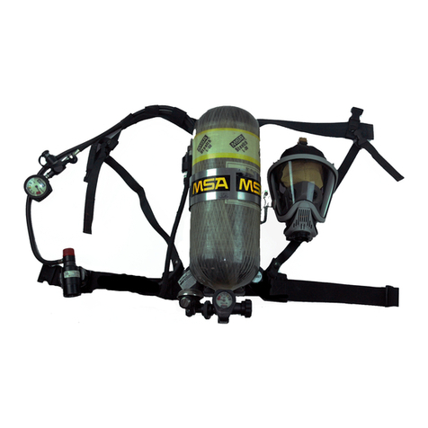
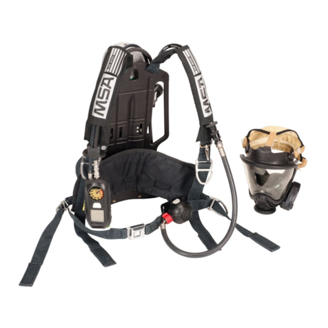
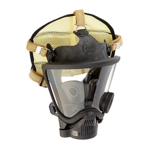
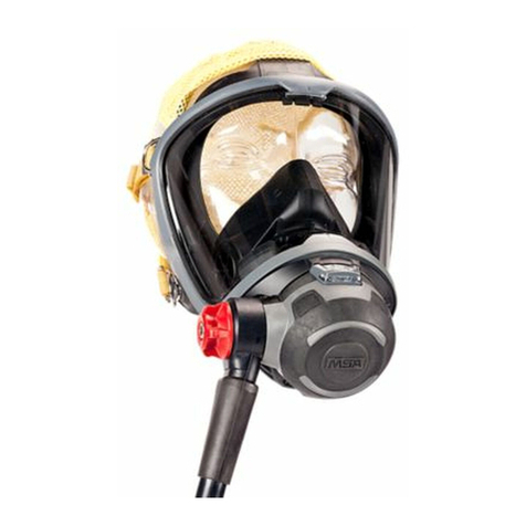
MSA FireHawk M7 Responder User manual

FireHawk®M7
Responder®Air Mask
NFPA 1982:2007 Edition
NFPA 1981:2007 Edition
CBRN A ent Approved Air Mask
OPERATION AND INSTRUCTIONS
This device complies with Part 15 of the FCC Rules. Operation is subject to the followin conditions:
(1) This device may not cause harmful interference and (2) this device must accept any interference that may cause
undesired operation.
TAL 803 (L) Rev. 1 © MSA 2008 Prnt. Spec. 10000005389(A) Mat. 10086011
Doc. 10086011
This manual must be carefully read and followed by all persons who have or will have the responsibility for usin
or servicin this air mask. This air mask will perform as desi ned only if used and serviced accordin to the instruc-
tions; otherwise it could fail to perform as desi ned, and persons who rely on the air mask could sustain serious
personal injury or death.
This Self-Co tai ed Breathi g Apparatus (SCBA) is certified by the Natio al I stitute of Occupatio al Safety a d Health
(NIOSH).
Cha ges a d modificatio s ot expressly approved by the ma ufacturer could void the user’s authority to operate the
equipme t.
The warra ties made by MSA with respect to the product are voided if the product is ot i stalled, used a d serviced i
accorda ce with the i structio s i this ma ual. Please protect yourself a d your employees by followi g the i structio s.
Please read a d observe the WARNINGS a d CAUTIONS i side. For a y additio al i formatio relative to use or repair,
write or call 1-800-MSA-2222 duri g regular worki g hours.
Use in conjunction with personal protective ensembles that provide appropriate levels of protection a ainst der-
mal hazards.
Some CBRN a ents may not present immediate effects from exposure, but can result in delayed impairment, ill-
ness, or death.
Direct contact with CBRN a ents requires proper handlin of the SCBA after each use and between multiple entries
durin the same use. Decontamination and disposal procedures must be followed. If contaminated with liquid
chemical warfare a ents, dispose of the SCBA after decontamination.
The respirator should not be used beyond 6 hours after initial exposure to chemical warfare a ents to avoid possi-
bility of a ent permeation.
FAILURE TO FOLLOW THE ABOVE ITEMS IN ADDITION TO ALL ESTABLISHED CBRN PROTECTIVE MEASURES CAN
RESULT IN SERIOUS PERSONAL INJURY OR DEATH.
DANGER

INTRODUCTION
NIOSH APPROVAL INFORMATION
CAUTIONS AND LIMITATIONS
I- Contains electrical parts which have not been evaluat-
ed as an ignition source in flammable or explosive
atmospheres by MSHA/NIOSH.
J- Failure to properly use and maintain this product could
result in injury or death.
M- All approved respirators shall be selected, fitted, used
and maintained in accordance with MSHA, OSHA and
other applicable regulations.
N- Never substitute, modify, add or omit parts. Use only
exact replacement parts in the configuration as speci-
fied by the manufacturer.
O- Refer to Users Instructions, and/or maintenance man-
uals for information on use and maintenance of these
respirators.
S- Special or critical User’s Instructions and/or specific
use limitations apply. Refer to user instructions before
donning.
CAUTIONS AND LIMITATIONS OF USE FOR CBRN
SCBA
Q- Use in conjunction with personal protective ensembles
that provide levels of protection against dermal haz-
ards.
R- Some CBRN agents may not present immediate
effects from exposure, but can result in delayed
impairment, illness, or death.
T- Direct contact with CBRN agents requires proper han-
dling of the SCBA after each use and between multi-
ple entries during the same use. Decontamination
and disposal procedures must be followed. If conta-
minated with liquid chemical warfare agents, dispose
of the SCBA after decontamination.
U- The respirator should not be used beyond 6 hours
after initial exposure to chemical warfare agents to
avoid possibility of agent permeation.
S - SPECIAL OR CRITICAL USER’S INSTRUCTIONS
1. Approved for use at temperatures above -25°F.
Approved only when the compressed-air container is
fully charged with air meeting the requirements of the
Compressed Gas Association Specification G-7 for
quality verification level (grade) D air or equivalent
specifications. The cylinder shall meet applicable DOT
specifications.
2. Do not alter this air mask. Altering will void the
Intrinsic-Safety rating and may affect the Intrinsic-
Safety of the device. Misuse or abuse of the heads-up
display system (FireHawk M7 Responder HUD),
FireHawk M7 Control Module, or FireHawk M7 Power
Module or using this equipment in a manner or situa-
tion not intended by the manufacturer, may result in
damage to the FireHawk M7 Responder HUD,
FireHawk M7 Control Module, or FireHawk M7 Power
Module, may result in personal injury or death to user
or persons dependent on the user. Always inspect the
FireHawk M7 Responder HUD for damage before use.
If damage is found, immediately remove the device
from service. The FireHawk M7 Responder HUD,
FireHawk M7 Control Module, and FireHawk M7
Power Module are approved intrinsically-safe and con-
form to UL/ANSI 913 for use in Class I, Div. I, Groups
C and D hazardous locations, temperature rating T3.
3. Use the air mask with adequate skin protection when
worn in gases and vapors that poison by skin absorp-
tion (for example: hydrocyanic-acid gas). In making
renewals or repairs, parts identical with those fur-
nished by the manufacturer under the pertinent
approval shall be maintained.
4. Approval for use against CBRN chemical warfare
agents is maintained only when using approved com-
ponents and following instructions listed on the
NIOSH approval supplement (P/N 10086012).
5. Do not mark the air mask, i.e., with stamps, labels,
paint, or other method. Use of such markings may
interfere with apparatus use or may constitute a flam-
mability hazard.
6. The mouth-bit can be inserted or removed from the
nosecup prior to use. See the “Preparing the
Respirator for Use” section for proper procedure.
2
TAL 803 (L) Rev. 1 - 10086011
TABLE OF CONTENTS
NIOSH Approval Information.............................................2
Special or Critical Users Instructions................................2
Instructions for Use and Care ...........................................5
Description ........................................................................7
Visual Inspection and Functional Tests ...........................11
Size Selection..................................................................15
Respirator Fit Test ...........................................................15
Preparing Respirator for Use...........................................17
Donning ...........................................................................19
Using the Air Mask ..........................................................23
Cold Weather Operation..................................................29
URC Assembly Operation ..............................................31
Hydration System............................................................33
Removing the Apparatus.................................................35
Cleaning and Disinfecting ...............................................39
Flow Test and Overhaul Requirements ..........................41
FireHawk M7 Telemetry Module......................................43
Accessories .....................................................................47
Quick-Fill®System Operation..........................................49
Extendaire™ System......................................................53
Lifetime Warranty.............................................................55
INTRODUCTION
Follow instru tion in the “Preparing the Respirator for
Use” se tion before inserting or removing the mouth-
bit in the nose up. Failure to follow this warning an
result in serious personal injury or death.
The nose up must be installed when using the
FireHawk M7 Responder Air Mask. Failure to follow
this warning an result in serious personal injury or
death.
7. For more information on the air mask use and perfor-
mance standards, refer to the following publications:
NFPA Standard 1500, Fire Department Occupational
Safety and Health Programs (Chapter 5) and NFPA
1981 Standard, on Open-Circuit SCBA’s for Fire
Service. Above publications are available from the
following: National Fire Protection Association,
Batterymarch Park, Quincy, MA 22269.
ANSI Standard Z88.5, Practices for Respiratory
Protection for the Fire Service; and, ANSI Standard
Z88.2, Practices for Respiratory Protection.
American National Standards Institute, 1430
Broadway, New York, NY 10018.
OSHA Safety and Health Standards (29 CFR 1910)
(see specifically Part 1910. 134), available from the
Superintendent of Documents, U. S. Government
Printing Office, Washington, DC 20402.
Compressed Gas Association, Inc., 1725 Jefferson
Davis Hwy., Suite 1004, Arlington, VA 22202.
Note: The FireHawk M7 Responder HUD, FireHawk M7
Control Module, and FireHawk M7 Power Module have
been tested and found to comply with the limits for a
Class B digital device, pursuant to Part 15 of the FCC
Rules. These limits are designed to provide reasonable
protection against harmful interference in a residential
installation. This equipment generates, uses, and can radi-
ate radio frequency and, if not installed in accordance
with instructions, may cause harmful interference to radio
communications. However, there is no guarantee that
interference will not occur in a particular installation. If this
equipment does cause interference to radio or television
reception, which can be determined by turning the equip-
ment off and on, the user is encouraged to try to correct
the interference by one or more of the following measures:
Reorient or relocate the receiving antenna
Increase the separation between the equipment and
the receiver
Connect the equipment into an outlet on a circuit dif-
ferent from that to which the receiver is connected.
Consult the dealer or an experienced radio/TV techni-
cian for help.
The FireHawk M7 Responder HUD, FireHawk M7
Control Module, and FireHawk M7 Power Module on-
tain ele tri al parts whi h have not been evaluated as
an ignition sour e in flammable or explosive atmos-
pheres by MSHA/NIOSH.
3TAL 803 (L) Rev. 1 - 10086011

NOTES
4

INSTRUCTIONS FOR USE AND CARE
1. Read and follow all NIOSH and other approval limi-
tations.
2. Do not use the arrier and harness assembly as a
verti al raising or lowering devi e.
3. Do not use the air mask as an underwater devi e.
4. This system must be supplied with respirable
[Quality Verifi ation Level (Grade) D, see ANSI/CGA
G-7.1-1989] or higher quality air; and a dew point
not to ex eed -65°F (24ppm v/v) [Compressed Gas
Asso iation Spe ifi ation G-7.1 for Quality
Verifi ation Level (Grade) D Gaseous Air].
5. This devi e may not seal properly with your fa e if
you have a beard, gross sideburns or similar physi-
al hara teristi s (see NFPA-1500 and ANSI
Z88.2). An improper fa ial seal may allow ontami-
nants to leak into the fa epie e, redu ing or elimi-
nating respiratory prote tion. Do not use this
devi e if su h onditions exist. The fa e-to-fa e-
pie e seal must be tested before ea h use. Never
remove the fa epie e ex ept in a safe, non-haz-
ardous, non-toxi atmosphere.
6. Return to a safe atmosphere immediately if dis ol-
oration, razing, blistering, ra king, or other dete-
rioration of the fa epie e lens material is
observed.
7. Users must wear suitable prote tive lothing and
pre autions must be taken so that the air mask is
not exposed to atmospheres that may be harmful
to it.
8. Take into a ount the following fa tors whi h may
affe t the duration or the servi e life.
a. the degree of physi al a tivity of the user;
b. the physi al ondition of the user;
. the degree that the user’s breathing rate is
in reased by ex itement, fear, or other emotional
fa tors;
d. the degree of training or experien e whi h the
user has had with this or similar equipment;
e. whether or not the ylinder is fully harged;
f. the presen e in the ompressed air of arbon
dioxide on entrations greater than the .04%
level normally found in atmospheri air;
g. the atmospheri pressure; if used in a pressur-
ized tunnel or aisson at 2 atmospheres (15 psi
gauge) the duration will be one-half as long as
when used at 1 atmosphere; at 3 atmospheres
the duration will be one-third as long; the servi e
life of the air mask is based on 1 atmosphere of
pressure.
h. the ondition of the air mask.
Failure to follow all warnings, instru tions, and estab-
lished prote tive measures an result in serious per-
sonal injury or death.
CBRN AGENT APPROVAL LABEL
The MSA CBRN Agent approved air mask has this
approval label attached to the carrier and harness.
IMPORTANT NOTICE FOR RESPIRATOR USERS AND
RESPIRATORY PROTECTION PROGRAM ADMINIS-
TRATORS
a. An adequate respiratory protection program must
include knowledge of hazards, hazard assessment,
selection of proper respiratory protective equipment,
instruction and training in the use of equipment,
inspection and maintenance of equipment, and med-
ical surveillance. [See OSHA regulations, Title 29 CFR,
Part 1910. 134 (c).]
b. This SCBA may be used only after proper instruction
and training in its use as specified in NFPA-1500 and
OSHA regulations Title 29 CFR, Part 1910.134.
c. Quantitative fit testing should be conducted to deter-
mine proper facepiece size prior to using the respira-
tor. The drink tube can be used for conducting quanti-
tative fit tests with the Ultra Elite Responder
Facepieces. The facepiece donning instructions must
be carefully followed when using the respirator and
when conducting fit tests.
Follow the instru tions in the “Respirator Fit Test”
se tion. Failure to do so an result in false prote tion
fa tor readings.
d. The CBRN Firehawk Second Stage Regulator must be
flow tested every year and overhauled on a periodic
basis. An overhaul kit (MSA P/N 10048942) is avail-
able.
5TAL 803 (L) Rev. 1 - 10086011
CBRN Agent Approved
See Instructions for Required Component
Part Numbers, Accessories, and Additional
Cautions and Limitations of Use.

CONTACT INFORMATION
In the event of a product concern, contact your local MSA
authorized repair center or distributor, who will provide the
necessary information to MSA for issue resolution. To
report any serious concerns, or to speak with a certifica-
tion organization, use the following contact information:
Manufa turer
MSA Customer Service
Phone: 1-800-MSA-2222
Certifying Agen ies
National Institute of Occupational Safety and Health
(NIOSH)
Phone: 412-386-6686
Safety Equipment Institute (SEI)
Phone: 703-442-5732
INSTRUCTIONS FOR USE AND CARE
6
TAL 803 (L) Rev. 1 - 10086011

DESCRIPTION
DESCRIPTION
FireHawk M7 Responder Air Masks from MSA are pres-
sure-demand, self-contained breathing apparatus (SCBA)
certified by the National Institute for Occupational Safety
and Health (NIOSH) for use in atmospheres immediately
dangerous to life or health:
``Immediately dangerous to life or health’’ means condi-
tions that pose an immediate threat to life or health or
conditions that pose an immediate threat of severe expo-
sure to contaminants, such as radioactive materials,
which are likely to have adverse cumulative or delayed
effects on health [Title 42 CFR, Part 84.2, (Q)].
This air mask complies with the National Fire Protection
Association (NFPA) Standard 1981 for Open-Circuit Self-
Contained Breathing Apparatus for Fire Fighters.
This air mask has been designated by NIOSH as being
CBRN (chemical, biological, radiological, and nuclear)
Agent Approved. It complies with the special tests under
NIOSH 42 CFR 84.63(c); Chemical Agent Permeation and
Penetration Resistance Against Distilled Sulfur Mustard
(HD) and Sarin (GB) and the Laboratory Respirator
Protection Level (LRPL) tests.
The FireHawk M7 Responder Air Mask consists of the fol-
lowing components.
PR14™ First Stage Regulator
Firehawk Responder Second Stage Regulator
Cylinder and Valve Assembly
Audi-Larm™ Audible Alarm with URC Assembly
FireHawk M7 Carrier and Harness Assembly
Ultra Elite®Responder Facepiece
Lens Plug
FireHawk M7 Responder HUD
FireHawk M7 Control Module
FireHawk M7 Power Module
Optional FIREHAWK M7 RESPONDER AIR MASK
COMPONENTS
Clear Command®Communications System
FireHawk M7 Telemetry Module
ExtendAire System
Quick-Fill System
Rescue Belt
FIREHAWK M7 RESPONDER AIR MASK
COMPONENTS
PR14 FIRST STAGE REGULATOR
The PR14 First Stage Regulator reduces the pressure
from the cylinder and valve assembly to an intermediate
pressure, which is in turn further reduced by the Firehawk
Responder Second Stage Regulator to a pressure that is
respirable by the user.
The PR14 First Stage Regulator incorporates a down-
stream design and dual springs.
The regulator incorporates a large, easily replaceable, sin-
tered filter to capture particulates that may be in the air
stream.
FIREHAWK RESPONDER SECOND STAGE
REGULATOR
The Firehawk Responder Regulator is a pressure-demand
regulator, which maintains a positive pressure in the face-
piece while the air mask is in use.
The Firehawk Responder Regulator attaches to the face-
piece via a push-to-connect feature.
The FireHawk Responder Regulator includes a pneumatic
plug that connects to the Ultra Elite Responder facepiece.
When the SCBA is pressurized, the pneumatic plug acti-
vates the pressure-demand exhalation valve.
The Firehawk Responder Regulator has a quick-connect
connection to the intermediate pressure hose.
CYLINDER AND VALVE ASSEMBLY
*As approved by NIOSH
The cylinder valve includes a metal valve body, threaded
connection for filling and attachment of the Audi-Larm
Alarm, handwheel, safety disc (burst disc), and pressure
gauge.
7TAL 803 (L) Rev. 1 - 10086011
Capa ity Pressure Rated Sv *
Cubi Ft. psig Life (Min.)
45 4500 30
88 4500 60
45 2216 30
45 2216 30
60 3000 30
66 4500 45

DESCRIPTION
The pressure gauge continuously shows the air pressure
in the cylinder.
The handwheel is used to open and close the cylinder
valve.
AUDI-LARM ALARM WITH URC ASSEMBLY
The Audi-Larm Alarm rings when there is approximately
25% of the air mask’s rated service time remaining and
when the cylinder valve is first opened, providing an audi-
ble indication that the alarm is working properly.
A high pressure hose delivers air at cylinder pressure from
the Audi-Larm Alarm to the PR14 First Stage Regulator.
Note: The remaining service time calculations are based
on a 40 LPM (liters per minute) NIOSH breathing rate.
All FireHawk M7 Responder Air Masks are equipped with
an Audi-Larm Alarm that includes a URC Assembly
(Universal Rescue Connection). The URC Assembly is a
male quick-fill inlet for use by Rapid Intervention Crews
for emergency filling of the SCBA or during transfill opera-
tions. Also included with the URC Assembly is a pressure
relief valve for protection of the cylinder burst disc.
FIREHAWK M7 CARRIER AND HARNESS ASSEMBLY
DO NOT use this arrier and harness assembly as a
verti al raising or lowering devi e. Failure to follow
this warning an result in serious personal injury or
death.
The carrier consists of a backplate, a cylinder band with
latch to hold the cylinder, and a harness, consisting of
shoulder pads, chest strap (optional), adjustable pull straps,
waist belt, waist belt mounted regulator retainer, swiveling
lumbar pad (optional), and Rescue Belt (optional).
ULTRA ELITE RESPONDER FACEPIECE
The facepiece includes a dual-mode exhalation valve.
When the facepiece is not connected to the FireHawk M7
Responder regulator, the exhalation valve operates as a
demand exhalation valve. When the facepiece is connect-
ed to a pressurized FireHawk M7 Responder regulator, the
exhalation valve operates as a pressure-demand exhala-
tion valve.
The facepiece lens is super-hardcoated to meet the
requirements of NFPA 1981.
The facepiece has a low-resistance, pressure-demand
exhalation valve.
An inhalation check valve in the inlet housing keeps mois-
ture and contaminants out of the Firehawk Responder
Regulator.
The facepiece has a speaking diaphragm for clear com-
munication.
The facepiece has a nose cup with a drink tube and can
be used with the SpeeD-ON® Head Harness.
The facepiece has a plug for the side port that must be
attached during use.
DO NOT use this fa epie e without the fa epie e plug
installed. Failure to follow this warning an result in
serious personal injury or death.
FIREHAWK M7 RESPONDER HUD
The FireHawk M7 Responder HUD, located on the Ultra
Elite Facepiece allows a user to see cylinder pressure in
one quarter cylinder increments, PASS pre-alarms, battery
status, and telemetry information (optional) while wearing
the air mask.
FIREHAWK M7 CONTROL MODULE (PASS DEVICE)
The FireHawk M7 Control Module is the user’s interface
with the air mask.
The FireHawk M7 Control Module is equipped with an
analog gauge as well as an LCD to provide the user vital
information: numeric and iconic cylinder pressure, battery
status, thermal alarm (optional), and time remaining.
If the air mask is equipped with the optional FireHawk M7
Telemetry Module, the radio link status and evacuation
alarms are displayed.
8
End of
Servi e
Cylinder Remaining Servi e Time
Time (Approx.) Indi ator
Pressure
(Approx)
30 min. 2216 psi 7 minutes 530 psi
30 min. 3000 psi 10 minutes 750 psi
30 min. 4500 psi 7 minutes 1125 psi
45 min. 4500 psi 11 minutes 1125 psi
60 min. 4500 psi 14 minutes 1125 psi

DESCRIPTION
The integrated PASS motion sensor is housed within the
FireHawk M7 Control Module.
FIREHAWK M7 POWER MODULE (PASS DEVICE)
The FireHawk M7 Power Module on the lower portion of
the backplate houses the batteries, serves as the cylinder
stop, emits audible PASS alarms, and has buddy lights.
The FireHawk M7 Power Module is linked to the FireHawk
M7 Control Module via the power cable.
OPTIONAL FIREHAWK M7 RESPONDER AIR MASK
COMPONENTS
CLEAR COMMMAND COMMUNICATION SYSTEM
The Clear Command Communication System is an elec-
tronic speech projection system available with either an
amplifier or an amplifier with radio interface connection.
FIREHAWK M7 TELEMETRY MODULE
The FireHawk M7 Telemetry Module provides the firefight-
er with two-way communication with Incident Command.
The firefighter’s vital statistics such as cylinder pressure,
service time remaining, PASS alarm, low battery alarm,
and thermal alarm are transmitted back to Incident
Command. Also, the firefighter has the ability to be evac-
uated remotely by Incident Command. The radio trans-
mitter is located inside of the FireHawk M7 Power
Module.
EXTENDAIRE SYSTEM
The ExtendAire System, located at the end of the interme-
diate pressure line, enables two users to share a common
air supply during emergency escape. The users can cou-
ple the Firehawk Responder Second Stage Regulator from
one user to the intermediate pressure manifold of the
other user. Both users will receive intermediate pressure
air from the donor's first stage regulator and cylinder. The
duration of the remaining air supply will be reduced by at
least half.
The SCBA is approved by NIOSH without inter-connect-
ing two users to one apparatus. NIOSH does not certify
“buddy breathers”. Therefore, the attachment of the
receiver's regulator to the donor's apparatus voids the
NIOSH approval for both air masks.
RESCUE BELT
The MSA Fire Service Rescue Belt is a personal escape
system integrated into an FireHawk M7 Carrier and
Harness Assembly. The system is designed to provide the
user a means of escape from an elevated position. Use of
the Rescue Belt must be in accordance with the user’s fire
department procedures. Care and use instructions are
provided under a separate manual, PN 10052748.
9TAL 803 (L) Rev. 1 - 10086011

NOTES
10

VISUAL INSPECTION AND FUNCTIONAL TESTS
INSPECTION
Conduct the Following: Before Use, After Each Use, and
Monthly
Thoroughly inspect this air mask upon receipt and before
use. This air mask is to be used only by trained and quali-
fied personnel. Read and understand these instructions
before attempting to use this equipment.
Inspect the entire air mask after it is cleaned and disin-
fected. NFPA-1500, as well as ANSI Standards Z88.2 and
Z88.5, describe three levels of inspection procedures
which are to be performed. Refer to these documents, or
to an inspection program prepared by a health profession-
al in establishing an inspection program.
If the air mask exhibits any of the onditions listed in
the Component Inspe tion se tion or if the air mask
does not fun tion properly as des ribed in the
Fun tional Tests se tion, the air mask must be
removed from servi e. Failure to follow this warning
an result in serious personal injury or death.
DO NOT inspe t the air mask before leaning if there
is danger of onta ting hazardous ontaminants.
Clean and disinfe t first, then inspe t. Failure to follow
this warning an ause inhalation or skin absorption
of the ontaminant and result in serious personal
injury or death.
Never substitute, modify, add, or omit parts. Use only
exa t repla ement parts in the onfiguration as spe i-
fied by the manufa turer. Failure to follow this warning
an result in serious personal injury or death.
COMPONENT INSPECTION
1. Facepiece
a. Inspect the facepiece, drink tube, and nose cup for
rubber deterioration, dirt, cracks, tears, holes, or
tackiness.
b. Inspect the head harness straps for tears, loss of
elasticity, or missing buckles or straps.
c. Inspect the lens for cracks, scratches, and a tight
seal with the facepiece rubber.
d. Ensure the exhalation valve is clean and operates
easily. The valve must move off the seat and return
when released.
e. Inspect the facepiece inlet for damage. Ensure the
spider gasket and valve disc are present.
f. Inspect the lens
receptacle and lens
plug
g. Ensure that the o-ring is in place and free of cracks,
tears, dirt, and distortion.
i. Check the threads to ensure they are not
rounded or nicked.
ii. Inspect the lens plug for cracks or other signs of
damage which could allow contaminants to enter
the housing.
h. Inspect the pneu-
matic receptacle o-
ring to be free of
cracks, tears, dirt,
and distortion.
i. Inspect the facepiece rubber behind the FireHawk
M7 Responder HUD and/or Clear Command
Communication System bracket (optional) for holes
or tears.
2. FireHawk M7 Responder HUD
a. Inspect the FireHawk M7 Responder HUD for
cracks or other signs of damage which could allow
contaminants to enter the housing.
b. Ensure that moisture or debris is not present in the
battery compartment.
c. Ensure the battery compartment o-ring on the bat-
tery cap is free of debris and not damaged or miss-
ing.
d. Reassemble the FireHawk M7 Responder HUD to
the bracket on the Ultra Elite Responder Facepiece.
3. Clear Command Communication System
a. Remove the amplifier housing from the facepiece
and inspect the housing for cracks or other signs of
damage
b. Ensure that the battery compartment is free of
moisture or debris.
c. Reassemble the amplifier housing on the facepiece.
d. Depress the on/off button on the unit and then
release it.
e. Look through the facepiece lens. The red LED
should be illuminated at the top of the amplifier unit.
f. Scrape a fingernail lightly across the voicemitter
11 TAL 803 (L) Rev. 1 - 10086011

VISUAL INSPECTION AND FUNCTIONAL TESTS
microphone grille of the voicemitter microphone
assembly.
g. Listen for this sound reproduced in the amplifier
speaker.
h. Depress and release the on/off button again to turn
the unit OFF. The LED on the amplifier unit should
be OFF.
4. Firehawk Responder Second Stage Regulator
a. The FireHawk M7 Responder Air Mask is equipped
with a quick-connect second stage intermediate
pressure hose, inspect the rubber washer for deteri-
oration, dirt, cracks, tears, or tackiness.
b. Ensure that the Firehawk Responder Regulator seal-
ing ring is seated properly in its groove on the outlet
of the regulator and that it is not torn, gouged, or
nicked.
c. Ensure that the FireHawk Responder Regulator
pneumatic plug is free of dirt and not damaged.
5. PR14 First Stage Regulator
a. Inspect the regulator mounting bracket (attached to
the backplate) for cracks, weakened areas, or signs
of heat or chemical related damage.
b. Inspect the regulator mounting bracket screws to
ensure they are secure.
c. Inspect the regulator mounting bracket to ensure
that it holds the regulator securely.
d. Inspect the pressure relief valve. Ensure that the
relief holes are clear and free of debris or other con-
taminants. Ensure that the pressure relief valve is
properly secured.
e. Inspect the hose connections. Ensure that the
hoses are properly secured.
6. Audi-Larm Alarm
a. Unthread the Audi-Larm Alarm coupling nut from
the cylinder valve. Inspect the coupling nut for
thread damage.
b. Ensure there is an o-ring present and not damaged.
Replace the o-ring if it is damaged.
c. Ensure that the bell is properly aligned and that the
screws are tight. If the bell is loose, remove the
alarm from service.
d. Inspect the relief valve for damage. Ensure the relief
valve label is not damaged and that the relief valve
ports are not showing. If damaged, remove the air
mask from service and replace the relief valve.
e. Reattach Audi-Larm Alarm to the cylinder valve.
7. High Pressure Hose
a. Inspect the high pressure hose between the Audi-
Larm Alarm and the PR14 First Stage Regulator.
Look for cuts or severe abrasions. If damage is pre-
sent, replace the hose.
8. Cylinder and Valve Assembly
a. Air mask cylinders should be recharged as soon as
possible after use. Cylinders should not be stored
partially charged for two reasons:
If used without recharge, the service life of the air
mask is reduced.
The cylinder burst disc vents excess pressure if a
full cylinder is over exposed to fire or heat. If the
cylinder is not full, it may be damaged before the
burst disc vents.
b. If the cylinder is less than FULL (within 10% of
rated service pressure), recharge it before storage.
Cylinder air must be at least CGA Quality
Verification Level (Grade) D respirable air. MSA rec-
ommends breathing air quality in accordance with
NFPA 1989.
c. Inspect the cylinder valve for signs of damage. The
valve may be opened slightly to ensure it operates
properly. Be sure to fully close the valve.
d. Inspect the cylinder body for cracks, dents, weak-
ened areas, corrosive agents causing the fibers to
break or peel, or signs of heat-related damage. If
the cylinder is damaged return it to an MSA Service
Center.
e. Check the hydrostatic test date on the cylinder
approval sticker located on the cylinder neck.
Fiberglass composite cylinders must be tested
every three years. Carbon-wrapped and steel cylin-
ders must be tested every five years.
f. Ensure the needle and gauge face on the cylinder
valve gauge are clearly visible and that the gauge
stem is not bent.
It is also essential that the required inspections and tests
be performed on all air mask cylinders in accordance with
Department of Transportation (DOT) regulations. DOT reg-
ulations require that composite cylinders be retired from
service after the fifteenth year. This does not include cylin-
der valve assemblies that may be reused. Steel and alu-
minum cylinder service life is indefinite if proper inspec-
tion and hydrostatic test procedures are followed and they
indicate that the cylinder may remain in service. Contact
an MSA distributor or sales associate for more information
regarding this policy.
Note: ANSI Z88.5 recommends checking cylinder pres-
sure weekly. For maximum safety the cylinders should be
stored full or empty (pressure above ambient but less than
100 psi).
9. FireHawk M7 Carrier and Harness
a. Operate the latch wing on the cylinder band to
ensure that it opens and closes properly and that it
holds the cylinder securely. If the cylinder band and
latch is locked, the latch wing should not turn.
b. Inspect the back plate for cracks, weakened areas,
or signs of damage due to heat or chemical related
damage.
c. Inspect all harness components for cuts, tears,
abrasions, or signs of damage due to heat or chem-
ical related damage.
10. FireHawk M7 Control Module
a. Inspect the gauge hose and power cable for any
visible signs of damage.
b. Inspect for external cracks in the housing and
ensure the rubber cover is not damaged.
c. Ensure the buttons are not damaged or missing.
d. Ensure the gauge hose and power cable are
12
TAL 803 (L) Rev. 1 - 10086011

VISUAL INSPECTION AND FUNCTIONAL TESTS
securely attached to the FireHawk M7 Control
Module.
11. FireHawk M7 Power Module
a. Inspect the FireHawk M7 Power Module housing for
external cracks and ensure that the FireHawk M7
Power Module, battery tube, and cylinder stop are
securely attached to the backplate.
b. Inspect the piezo emitters on both sides of the
FireHawk M7 Power Module. Ensure that the emit-
ter covers are not obstructed by dirt or debris.
c. Ensure that the power cable is securely attached to
the FireHawk M7 Power Module. The fitting on the
power cable should not be able to be unthreaded
by hand.
d. Remove the cap from the battery tube. Ensure that
the o-ring is properly installed on the battery cap, if
o-ring is missing, it must be replaced.
e. Inspect the inside of the battery tube. Ensure that
the battery terminals are not corroded and that the
tube if free of moisture and debris.
f. Replace the battery cap on the battery tube.
12. Record Keeping
a. Following inspection, the date and initials of the
designated inspector should be recorded on an
inspection tag. A more detailed record of the opera-
tions performed can be noted on an inspection and
maintenance log, available from MSA. When the
inspection data has been recorded, the air mask is
ready for use.
All repair and repla ement of subassemblies must be
arried out by an MSA ertified repair te hni ian.
Failure to follow this warning will void NFPA and
NIOSH ertifi ations and an result in serious person-
al injury or death.
FUNCTIONAL TESTS
Condu t the Following: Before Use, After Ea h Use,
and Monthly
1. Check that the Firehawk Responder Regulator and
facepiece can hold a negative pressure.
a. Close the cylinder valve and purge any air from the
system using the bypass knob on the Firehawk
Responder Regulator.
b. Hold the facepiece against the face to create an
effective seal.
c. Attach the Firehawk Responder Regulator to the
facepiece and inhale until the facepiece begins to
collapse against the face. (See “Installing the
FireHawk Responder Regulator” Section for instruc-
tion on installing FireHawk Responder Regulator).
Hold breath for approximately 10 seconds. Negative
pressure should be maintained and the facepiece
should remain collapsed against the face for the
entire 10 seconds.
d. Do not use the air mask if negative pressure cannot
be maintained in the facepiece. Return the Firehawk
Responder Regulator and facepiece to a certified
repairperson.
2. Check Firehawk Responder Regulator operation.
Note: Firehawk Responder Regulator functional checks
must be conducted with a full cylinder. Check the pres-
sure gauge on the cylinder valve to verify that the cylinder
is full.
a. Push the release buttons on the side of the regula-
tor.
b. Ensure that the regulator bypass knob is fully
closed (clockwise).
c. Slowly open the cylinder valve to pressurize the air
mask. Ensure that the cylinder valve is completely
opened.
d. Open the Firehawk Responder Regulator bypass
knob (counter-clockwise). Ensure that air flows from
the regulator. Close the bypass knob (clockwise).
e. Attach the regulator to the facepiece. Ensure proper
regulator attachment by pulling on the regulator.
f. Don the facepiece or hold the facepiece against the
face to create an effective seal.
g. Inhale sharply to start air flow. Breathe normally.
Ensure proper regulator response. The regulator
should not make any unusual sounds including
whistling, chattering, or popping.
h. Remove the facepiece from the face. Ensure that air
flows freely. Push the regulator release buttons.
Ensure that air flow stops.
i. If the regulator fails to meet any of the above
checks, remove the air mask from service. Return
the regulator to a certified repairperson.
3. FireHawk M7 Responder HUD, FireHawk M7 Control
Module, FireHawk M7 Power Module, and Audi-Larm
Alarm
a. Verify proper function of the FireHawk M7
Responder HUD, FireHawk M7 Control Module,
FireHawk M7 Power Module, and Audi-Larm Alarm
by observing the FireHawk M7 Control Module
gauge and display when the alarms ring and tone.
Perform this test with a minimum cylinder pressure
of 1200 psi for 2216 psi air masks, 1800 psi for
3000 psi air masks, and 2000 psi for 4500 psi air
masks.
b. Pressurize the system by opening the cylinder
valve. Listen for the FireHawk M7 Power Module to
sound and for the Audi-Larm Alarm to ring briefly.
c. Look through the facepiece lens at the LED display
of the FireHawk M7 Responder HUD, the LEDs
must illuminate and show cylinder pressure (See
“FireHawk M7 Responder HUD Functionality”
Section for information on HUD LED patterns.
d. Ensure that the alarm button on the FireHawk M7
Control Module and the buddy lights on the
FireHawk M7 Power Module are slowly flashing
green.
13 TAL 803 (L) Rev. 1 - 10086011

VISUAL INSPECTION AND FUNCTIONAL TESTS
e. Allow the FireHawk M7 Control Module to remain
motionless for approximately 20 seconds. Listen for
the FireHawk M7 Power Module to sound the low
volume repeated tones of the PASS pre-alarm.
Verify that the alarm button on the FireHawk M7
Control Module and the buddy lights of the
FireHawk M7 Power Module are slowly flashing red.
Also verify that the orange LED is displayed in the
FireHawk M7 Responder HUD. Ensure that the
FireHawk M7 Control Module remains motionless
until the full PASS alarm activates. Listen for the
FireHawk M7 Power Module to sound the loud
PASS alarm. Look for the alarm button on the
FireHawk M7 Control Module and the buddy lights
on the FireHawk M7 Power Module to rapidly flash
red.
f. Reset the PASS alarm by pressing the reset button
(yellow) on the side of the FireHawk M7 Control
Module two times within approximately one second.
g. To check the manual activation of the PASS alarm,
press and hold the alarm button on the front of the
FireHawk M7 Control Module for approximately
three seconds. Listen for the PASS alarm to be
emitted from the FireHawk M7 Power Module.
h. Reset the PASS alarm. Press the reset button (yel-
low) on the FireHawk M7 Control Module two times
within approximately one second.
i. Allow the FireHawk M7 Control Module to remain
motionless until the PASS pre-alarm sounds. Shake
the FireHawk M7 Control Module to reset the alarm.
j. Disconnect the Firehawk Responder Regulator from
the facepiece.
k. Close the cylinder valve fully.
l. Slowly crack the bypass valve on the Firehawk
Responder Regulator to bleed off pressure until the
FireHawk M7 Control Module pressure reading
drops below the following values:
o530 psi - approximately (2216 psi system)
o 750 psi - approximately (3000 psi system)
o1050 psi - approximately (4500 psi system)
A single flashing red LED must display in the
FireHawk M7 Responder HUD at the appropriate
pressure listed above. The Audi-Larm Alarm will ring
and the alarm button on the FireHawk M7 Control
Module and buddy lights on the FireHawk M7
Power Module will flash red at this time.
m.The alarms should continue until the air pressure is
200 psi or less. If the Audi-Larm Alarm, FireHawk
M7 Control Module, FireHawk M7 Power Module, or
FireHawk M7 Responder HUD does not function
properly, the air mask must be removed from ser-
vice.
n. When the system pressure falls below 200 psi, turn
the FireHawk M7 Control Module off (sleep mode)
by pressing the reset button (yellow) two times with-
in approximately one second.
o. Open the bypass valve slowly to release any
remaining pressure in the system. Close the bypass
valve.
DO NOT dis onne t the Audi-Larm Alarm oupling nut
when pressure is shown on the FireHawk M7 Control
Module gauge or display. Release all pressure from
the air mask by opening the Firehawk Responder
Regulator bypass valve. Removing the oupling nut
with the air mask is pressurized an result in serious
personal injury, death, or damage to equipment.
14
TAL 803 (L) Rev. 1 - 10086011

SIZE SELECTION
Regardless of facial dimensions and respirator sizing
charts, an actual respirator fit test, either qualitative or
quantitative must be performed to ensure the correct res-
pirator size selection.
Fit test the respirator size relative to your facial features
and dimensions. The Safety Administrator or Program
Manager might assist in selecting the initial size to try.
Carefully don the mask and conduct a negative pressure
seal test. See donning instructions for procedure.
If the facepiece does not pass the negative pressure seal
test or feels uncomfortable, try the next nearest size rela-
tive to your face.
Passing the negative pressure seal test does not verify the
size is correct. The size selected must be verified by suc-
cessfully passing a Respirator Fit Test, either qualitative or
quantitative. If the respirator passes a negative pressure
seal test but DOES NOT pass a Respirator Fit Test, try the
next nearest size.
Once the proper size is selected, the respirator must pass
a negative pressure seal test every time the facepiece is
donned to ensure proper fit before using the respirator.
If other than facial seal leakage is detected, the condition
must be investigated and corrected before another test is
made.
The facepiece must also pass the negative pressure seal
test before the user attempts to enter a toxic atmosphere.
The facepiece will not furnish protection unless all inhaled
air is drawn through the SCBA.
RESPIRATOR FIT TEST
The user must perform a respirator fit test
(Quantitative Test or Qualitative Test) and follow all
warnings and limitations spe ified. Failure to do so
an result in serious personal injury or death.
A qualitative or quantitative respirator fit test must be car-
ried out routinely for each wearer of this respirator to
determine or confirm the amount of protection that the
respirator provides. The fit test method chosen may
impact the maximum use concentration.
Quantitative Test – If a quantitative fit test is used, a fit
factor of at least 500, based on ambient aerosol fit test
methods or equivalent, is required before any type of res-
pirator is assigned to an individual.
Qualitative Test – If a qualitative fit test is used, only vali-
dated protocols are acceptable. The individual must pass
a test designed to assess a fit factor of at least 500.
When this fa epie e is used with the FireHawk M7
Responder APR, a fit fa tor of at least 2000 is required
for Quantitative or Qualitative test. Failure to do so
an result in serious personal injury or death.
Respirator fit tests are explained fully in the American
National Standard Practices for Respiratory Protection,
ANSI Z88.2-1992 which is published by the American
National Standards Institute, 11 West 42nd Street, New
York, New York, 10036 and Occupational Safety and
Health Standards, OSHA 1910.134, which is published by
the Occupational Safety and Health Administration, 200
Constitution Avenue, NW, Washington DC, 20210.
Using the Drink Tube for Fit Testing
The drink tube can be used for fit testing.
To use the drink tube for fit testing, perform the following:
1. Remove the nosecup from the facepiece.
2. Place the mouth-bit
between the lens
receptacle and speak-
ing diaphragm retainer.
3. Perform fit test.
Be sure the mouth bit does not onta t the fa e dur-
ing fit testing. Failure to do so an result in false pro-
te tion fa tor readings.
15 TAL 803 (L) Rev. 1 - 10086011

NOTES
16

PREPARING THE RESPIRATOR FOR USE
CHECKPOINTS BEFORE USE
1. Check that all parts of the respirator are complete and
undamaged. See the Visual Inspection and Functional
Test section for Inspection Procedures.
INSTALLING/REMOVING MOUTH-BIT AND NOSECUP
The nose up must always be installed when using the
FireHawk M7 Responder Air Mask. Failure to follow
this warning an result in serious personal injury or
death.
This facepiece was designed with the option of being
used with or without the mouth-bit.
Removing the mouth-bit from the nosecup:
1. Remove the nosecup from the facepiece.
2. Push and hold the
stem of the mouth-bit
to the left side of the
mask just underneath
the APR lens recepta-
cle.
3. Place the nosecup in the facepiece and position it so
its rubber ring faces toward the plastic retainer ring.
4. Starting at the top,
stretch and push the
rubber ring of the
nosecup under the
plastic retainer ring of
the speaking
diaphragm assembly.
5. Continue stretching the nosecup ring and work it into
place.
6. Be sure that the nose-
cup does not get
caught on the lens
retainer.
7. Stretch the oval opening in the nosecup around the lip
on the exhalation valve in the component housing.
Inserting the drink tube into the nose up:
1. Place the nosecup in the facepiece and position it so
its rubber ring faces toward the plastic retainer ring.
2. Locate the “X” cut in
the nosecup and slide
the mouth-bit through
the “X”. Push the
nosecup down the
drink tube until it stops.
3. Starting at the top, stretch and push the rubber ring of
the nosecup under the plastic retainer ring of the
speaking diaphragm assembly.
4. Continue stretching the nosecup ring and work it into
place.
5. Be sure that the nose-
cup does not get
caught on the lens
retainer.
6. Stretch the oval opening in the nosecup around the lip
on the exhalation valve in the component housing.
7. Don the facepiece to ensure the mouth-bit is accessi-
ble to use.
17 TAL 803 (L) Rev. 1 - 10086011

PREPARING THE RESPIRATOR FOR USE
The nose up an get aught on the lens retainer aus-
ing the inhalation valve to be in the open position.
Verify the inhalation valve is not stu k in the open
position prior to use. Failure to follow this warning
an result in serious personal injury or death.
INSTALLING LENS PLUG
1. Ensure the o-ring inside the lens receptacle is in place
and free of cracks, tears, dirt, and distortion.
2. Thread the lens plug into the lens receptacle hand
tight.
The lens plug must be installed during use as a Self-
Contained Breathing Apparatus (SCBA). Failure to fol-
low this warning will void NFPA and NIOSH ertifi a-
tions and an result in serious personal injury or
death.
18
TAL 803 (L) Rev. 1 - 10086011

DONNING
DONNING THE AIR MASK
1. Remove the facepiece from the case or bag.
DO NOT use a over lens in a high-temperature envi-
ronment, su h as firefighting. High temperatures may
distort the over lens. Or, moisture trapped between a
over lens and the fa epie e lens may ondense and
distort vision. Always remove the over lens before
donning the fa epie e. Failure to follow this warning
an result in serious personal injury or death.
2. Ensure that the cylinder is fully pressurized.
3. Reach the right arm inside the right shoulder straps
and grasp the FireHawk M7 Control Module. Slide the
left arm through the left shoulder straps.
4. Bend forward slightly; resting the carrier on the back.
5. Attach the chest strap buckle (optional).
6. Fasten the waist belt and pull it tight for a snug fit.
Most of the air mask weight should be carried on the
hips.
7. Stand up straight. Pull the shoulder strap pull tabs out
to tighten the shoulder straps. Additional adjustments
to the waist belt may be needed.
8. The shoulder straps and waist strap ends must be
tucked in and lay flat across the body.
BEFORE USING THE AIR MASK
1. Grasp the Firehawk Responder Regulator and push
the side buttons.
2. Ensure that the red
bypass knob is fully
closed (clockwise).
3. Reach behind and fully
open the cylinder valve.
Be sure that you are opening the ylinder valve and
not removing battery over. Failure to follow this
warning an result in serious personal injury or death.
Listen for any hiss or pop sounds from the Audi-Larm
Alarm, if heard, do not use the air mask. Return it to
an MSA trained or ertified repairperson. Failure to
follow this warning an result in serious personal
injury or death.
4. As the system pressure rises from 50 to 200 psi, both
visible and audible alerts activate automatically, indi-
cating that the air mask is functioning properly. Such
alerts include a brief ring from the Audi-Larm Alarm, a
chirp from the FireHawk M7 Power Module, and the
start-up sequence of the FireHawk M7 Responder
HUD LEDs.
DO NOT use the air mask if the Audi-Larm Alarm fails
to ring, the FireHawk M7 Power Module fails to sound,
or the FireHawk M7 Responder HUD fails to light, the
air mask must be he ked and orre ted for proper
operation by an MSA trained or ertified repairperson
before using. Failure to follow this warning an result
in serious personal injury or death.
5. No air should flow from
the Firehawk
Responder Regulator. If
it does, repeat steps 1
and 2.
6. Check the pressure gauge and display on the
FireHawk M7 Control Module and the LED display on
the FireHawk M7 Responder HUD. These pressure
indicators should be within 110 psi for 2216 psi sys-
tems, 150 psi for 3000 psi systems, 225 psi for 4500
psi systems.
DO NOT use the air mask if the pressure readings do
not agree with the ylinder pressure indi ated on the
ylinder valve gauge. Return it to an MSA trained or
ertified repairperson.
19 TAL 803 (L) Rev. 1 - 10086011

DONNING
7. Check the Firehawk
Responder Regulator’s
bypass operation.
Grasp the red knob
and turn it counter-
clockwise. Listen for
airflow and then turn it
to the off position.
8. Fully close the cylinder valve.
9. Listen for air leaks and watch the pressure gauge and
display on the FireHawk M7 Control Module for 10
seconds.
DO NOT use the air mask if the pressure drops more
than 100 psi in ten se onds, the air mask must be
repaired; otherwise, redu ed servi e life may result.
10. Crack the Firehawk Responder Regulator bypass
valve slowly to bleed off pressure until the FireHawk
M7 Responder HUD and FireHawk M7 Control Module
displays drop below:
530 psi-approximately (2216 psi system)
750 psi-approximately (3000 psi system)
1125 psi-approximately (4500 psi system)
At these pressures the FireHawk M7 Responder HUD
should display a flashing red LED, the Audi-Larm Alarm
should ring continuously, and the alarm button on the
FireHawk M7 Control Module and the buddy lights on the
FireHawk M7 Power Module should be flashing red.
11. When the system pressure falls below 200 psi, turn
the FireHawk M7 Control Module off by depressing
the reset button (yellow) two times within approxi-
mately one second.
DO NOT use the air mask if the Audi-Larm Alarm fails
to ring or fails to ontinuously ring down to pressures
of 200 psi, or if the FireHawk M7 Control Module or
FireHawk M7 Responder HUD fails to light properly.
The air mask must be he ked and orre ted for
proper operation by an MSA trained or ertified repair-
person before using. Failure to follow this warning an
result in serious personal injury or death.
Note: The FireHawk M7 Responder HUD will automatical-
ly turn itself OFF approximately 60 seconds after the air
mask has been depressurized. A single red LED will flash
until the device turns off.
DONNING THE FACEPIECE
DO NOT wear eyeglasses under the fa epie e. The
temples or sidebars on eyeglasses will prevent an air-
tight seal. If you must wear glasses, install an
approved spe ta le kit listed on the NIOSH approval
label. Failure to follow this warning an ause inhala-
tion of ontaminated air, resulting in serious respirato-
ry injury or death.
Note: Before donning, ensure that the Firehawk
Responder Regulator sealing ring is seated properly in its
groove on the outlet of the regulator and that it is not torn,
gouged, or nicked.
1. Loosen all the harness
straps. Grip the bottom
straps.
2. Insert chin into the
lower part of facepiece,
then pull the harness
back over the head.
3. Pull the back of har-
ness downward until
centered at the back of
the head.
20
TAL 803 (L) Rev. 1 - 10086011
Table of contents
Other MSA Respiratory Product manuals

MSA
MSA G1 Industrial SCBA User manual

MSA
MSA 3S-H/F1 User manual

MSA
MSA G1 PAPR User manual

MSA
MSA OptimAir 6A User manual

MSA
MSA OptimAir MM 2K User manual

MSA
MSA BlackHawk MMR User manual

MSA
MSA Ultra Elite P100 User manual

MSA
MSA G1 APR User manual

MSA
MSA SavOxCap 60 User manual

MSA
MSA Duo-Flo User manual

MSA
MSA Versa-Hood User manual

MSA
MSA AUER SSR 90 User manual

MSA
MSA PremAire Cadet 15M Manual

MSA
MSA SSR 30/100 User manual

MSA
MSA AUER SavOx User manual

MSA
MSA TransAire 10008292 User manual

MSA
MSA G1 AirHawk II SCBA User manual

MSA
MSA FIREHAWK M7 ULTRA ELITE 10084690 Setup guide

MSA
MSA Turbo-Flo B1260 009 User manual

MSA
MSA Ultra Elite Responder Operating instructions