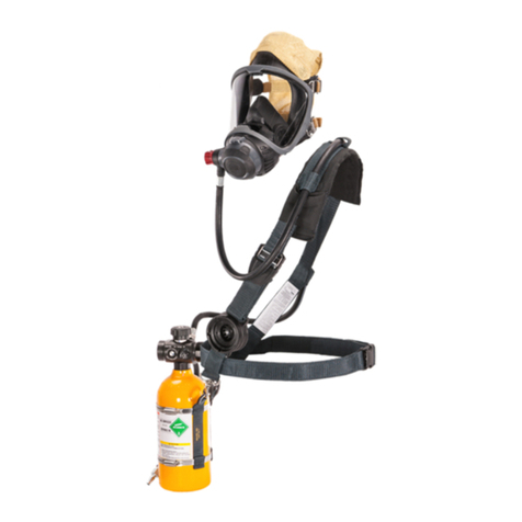
MSA G1 SCBA User manual

MSAsafety.com
Certified Air Mask Repair Education (C.A.R.E.) Manual
G1
Regulator with Quick Acting Bypass
Order No.: 10180091/01
CR 800000024801

1000 Cranberry Woods Drive
Cranberry Township, PA 16066
USA
Phone 1-800-MSA-2222
Fax 1-800-967-0398
For your local MSA contacts please go to our website www.MSAsafety.com
© MSA 2018. All rights reserved
WARNING!
Read this manual carefully before servicing the device. The device will perform as designed only if it is used
and maintained in accordance with the manufacturer's instructions. Otherwise, it could fail to perform as
designed and persons who rely on this device for their safety could sustain serious personal injury or death.
Please read and observe the WARNINGS and CAUTIONS inside. For any additional information relative to
use or repair, call 1-800-MSA-2222 during regular working hours.

3
G1
US
Contents
1 G1 Regulator . . . . . . . . . . . . . . . . . . . . . . . . . . . . . . . . . . . . . . . . . . . . . . . . . . . . . . . . . . . . . . . . . . . . . . . . . 4
1.1 Replacement Kits . . . . . . . . . . . . . . . . . . . . . . . . . . . . . . . . . . . . . . . . . . . . . . . . . . . . . . . . . . . . . . . . . . 4
1.2 Required Tools and Equipment . . . . . . . . . . . . . . . . . . . . . . . . . . . . . . . . . . . . . . . . . . . . . . . . . . . . . . . 4
1.3 Parts List. . . . . . . . . . . . . . . . . . . . . . . . . . . . . . . . . . . . . . . . . . . . . . . . . . . . . . . . . . . . . . . . . . . . . . . . . 5
2 Maintenance and Care . . . . . . . . . . . . . . . . . . . . . . . . . . . . . . . . . . . . . . . . . . . . . . . . . . . . . . . . . . . . . . . . 7
2.1 Removing the Regulator Cover . . . . . . . . . . . . . . . . . . . . . . . . . . . . . . . . . . . . . . . . . . . . . . . . . . . . . . . 7
2.2 Installing the Regulator Cover . . . . . . . . . . . . . . . . . . . . . . . . . . . . . . . . . . . . . . . . . . . . . . . . . . . . . . . . 8
2.3 Removing the Regulator Hose Assembly. . . . . . . . . . . . . . . . . . . . . . . . . . . . . . . . . . . . . . . . . . . . . . . 10
2.4 Installing the Regulator Hose Assembly. . . . . . . . . . . . . . . . . . . . . . . . . . . . . . . . . . . . . . . . . . . . . . . . 11
2.5 Removing the Regulator Spring and Spring Retainer. . . . . . . . . . . . . . . . . . . . . . . . . . . . . . . . . . . . . .12
2.6 Installing the Regulator Spring and Spring Retainer. . . . . . . . . . . . . . . . . . . . . . . . . . . . . . . . . . . . . . . 12
2.7 Removing the Diaphragm. . . . . . . . . . . . . . . . . . . . . . . . . . . . . . . . . . . . . . . . . . . . . . . . . . . . . . . . . . . 13
2.8 Installing the Diaphragm. . . . . . . . . . . . . . . . . . . . . . . . . . . . . . . . . . . . . . . . . . . . . . . . . . . . . . . . . . . . 14
2.9 Disassembling the Bypass and Hose with Swivel . . . . . . . . . . . . . . . . . . . . . . . . . . . . . . . . . . . . . . . . 14
2.10 Installing the Bypass and Hose with swivel Assembly . . . . . . . . . . . . . . . . . . . . . . . . . . . . . . . . . . . . . 15
2.11 Removing the Valve Assembly . . . . . . . . . . . . . . . . . . . . . . . . . . . . . . . . . . . . . . . . . . . . . . . . . . . . . . . 16
2.12 Installing the Valve Assembly . . . . . . . . . . . . . . . . . . . . . . . . . . . . . . . . . . . . . . . . . . . . . . . . . . . . . . . . 17
2.13 Removing the Regulator Buttons . . . . . . . . . . . . . . . . . . . . . . . . . . . . . . . . . . . . . . . . . . . . . . . . . . . . . 18
2.14 Installing the Regulator Buttons . . . . . . . . . . . . . . . . . . . . . . . . . . . . . . . . . . . . . . . . . . . . . . . . . . . . . . 19
2.15 Removing the E-Module . . . . . . . . . . . . . . . . . . . . . . . . . . . . . . . . . . . . . . . . . . . . . . . . . . . . . . . . . . . . 20
2.16 Installing the E-Module . . . . . . . . . . . . . . . . . . . . . . . . . . . . . . . . . . . . . . . . . . . . . . . . . . . . . . . . . . . . . 20
2.17 Removing the Regulator Seal Ring . . . . . . . . . . . . . . . . . . . . . . . . . . . . . . . . . . . . . . . . . . . . . . . . . . . 21
2.18 Installing the Regulator Seal Ring . . . . . . . . . . . . . . . . . . . . . . . . . . . . . . . . . . . . . . . . . . . . . . . . . . . . 21
2.19 Removing the Regulator Housing. . . . . . . . . . . . . . . . . . . . . . . . . . . . . . . . . . . . . . . . . . . . . . . . . . . . . 22
2.20 Installing the Regulator Housing. . . . . . . . . . . . . . . . . . . . . . . . . . . . . . . . . . . . . . . . . . . . . . . . . . . . . . 22

4
G1 Regulator
G1
US
1G1Regulator
1.1 Replacement Kits
Model 7-2779-1 Regulator Assemblies
Overhaul Kits
1.2 Required Tools and Equipment
Description Part
Number Purge QC
Hose
Cont.
Hose
G1 Replacement Regulator, Quick-Connect, Quick Acting Bypass 10180486 X X
G1 Replacement Regulator, Continuous, Quick Acting Bypass 10180487 X X
G1 Replacement Regulator, Quick-Connect (Solid), Quick Acting
Bypass 10180488 X
G1 Replacement Regulator, Continuous (Solid), Quick Acting Bypass 10180489 X
G1 Replacement Regulator, Quick-Connect, Regulator Side Only,
Quick Acting Bypass 10180490 X X
G1 Replacement Regulator, Quick-Connect (Solid), Regulator Side
Only, Quick Acting Bypass 10180491 X
Description Part Number
Regulator Overhaul Kit 10180113
Description Part Number
T40 Torx Bit (1/4”) 10176844
Adjustable TorqueVario, 10 - 50 in-lbs 10175879
Torque Control Square Drive Adapter Blade for 1/4"Sockets 10175880
Torx SoftFinish Driver T40 x 80 mm 10164581
Pliers, Snap Ring, Adjustable, 90 Degree 10164602
O-Ring Removal Tool 636060
Flat Blade Screwdriver

5
G1 Regulator
G1
US
1.3 Parts List
Fig. 1 Exploded View

6
G1 Regulator
G1
US
Item Quantity Description Part Number
1 3 O-RING, SILICONE, SIZE 12, RED 697453
2 1 SPRING, PD 10180070
3 1 DIAPHRAGM 10039172
4 1 SHIELD ASSEMBLY, FIREHAWK, CBRN 10044026
5 1 CAP, SPRING 10047528
6 2 O-RING, FKM, 75D, 8MM, GREEN 10162839-SP
7 2 O-RING, SILICONE, 70D, SIZE 008, ORANGE 10082499-SP
8A 1 COVER, G1 REGULATOR, NON-PURGE 10146190-SP
8B 1 COVER, G1 REGULATOR, PURGE 10146212-SP
9 1 BUTTON, BUDDY LIGHT, G1 REGULATOR 10146218-SP
10 1 BUTTON, ACTUATOR, GREY 10146220-SP
11 1 RETAINER, SPRING 10146229-SP
12 1 SPRING, BUTTON 10146237-SP
13 1 GASKET, SEAL, RING 10146238-SP
14 1 CONE, ADJUSTER 10146240-SP
15 1 KNOB 10146252-SP
16 1 RETAINER, NUT, KNOB 10146253-SP
17 1 BYPASS 10179026
18 1 COVER, SWIVEL, G1 REGULATOR, ELEK 10153346-SP
19 2 O-RING, EPDM, 80D, SIZE 007, BLACK 10153637-SP
20 1 O-RING, SILICONE, 70D, SIZE 013, ORANGE 10153638-SP
21 1 O-RING, SILICONE, 70D, SIZE 24, ORANGE 10153639-SP
22 1 RETAINER, RING, SNAP, EXTERNAL, 7/16 IN 10153642-SP
23 1 E-MODULE ASSEMBLY 10156469-SP
24 1 VALVE ASSEMBLY 10179024
25 1 U-CLIP, RETAINER 10159816-SP
26 A 1 G1 REG HOSE ASSEMBLY WITH QA BYPASS, CONT 10184318
26 B 1 G1 REG HOSE ASSEMBLY WITH QA BYPASS, QC 10184317
26 C 1 G1 REG HOSE ASSEMBLY WITH QA BYPASS, QC, REG SIDE 10184316
27 1 G1 REG HOUSING ASSEMBLY WITH RFID ELEC 10164892
28 1 G1 REG HOSE ASSEMBLY, QC, PRESS RED SIDE 10153621-SP
29 1 BUTTON ASSY, BUDDY LIGHT, G1 REGULATOR 10160363-SP
CONTAINS BUTTON, BUDDY LIGHT, G1 REGULATOR 10146218-SP
O-RING, SILICONE, 70D, SIZE 008, ORANGE 10082499-SP
O-RING, EPDM, 80D, SIZE 007, BLACK 10153637-SP
30 1 BUTTON ASSY, ACTUATOR, GREY 10160350-SP
CONTAINS BUTTON, ACTUATOR, GREY 10146220-SP
O-RING, SILICONE, 70D, SIZE 008, ORANGE 10082499-SP
O-RING, EPDM, 80D, SIZE 007, BLACK 10153637-SP
31 1 O-RING 633553
CHRISTO-LUBE 604070
LOCTITE 243 10110981

7
Maintenance and Care
G1
US
2 Maintenance and Care
WARNING!
DO NOT attempt to maintain or repair the G1 SCBA while pressurized. Attempting to disassemble a pres-
surized SCBA can cause parts to become airborne or swing at very high rates of speed. Failure to follow
this warning can result in serious personal injury or death.
2.1 Removing the Regulator Cover
(1) Turn the regulator port side up.
(2) Press and hold the release buttons.
(3) Use a flat blade screwdriver to release the regulator
housing retaining tabs.
(4) Allow the cover, attached spring, spring cap, and CBRN
shield to drop into your palm.
CAUTION! Handle the CBRN Shield by the rim only to
avoid damage.
(5) Inspect the regulator cover, spring and CBRN shield.
a) Replace the regulator cover if cracked, burned or
otherwise damaged.
b) Replace the spring if static pressure is too high or too
low. (Not usually a part that would be replaced.)
c) Replace the CBRN shield and spring cap if torn,
cracked, or otherwise damaged.

8
Maintenance and Care
G1
US
2.2 Installing the Regulator Cover
WARNING!
Visually inspect the U-clip to ensure that it is in place and has not become dislodged or fallen out of the
regulator housing before attaching the regulator cover. Ensure proper engagement of both retaining tabs by
visual inspection to ensure that the regulator cover is securely attached to the regulator housing. Failure to
follow this warning could cause the regulator to malfunction resulting in serious personal injury or death.
NOTE: Procedure applies to the purge and non-purge regulator cover.
(1) Push the regulator shut off buttons to ensure the valve
fork is set in the raised position.
NOTE: Ensure the diaphragm is seated securely over the
regulator housing. (See Installing the Diaphragm for instruc-
tions.)
(2) Apply a thin coating of Christo-Lube lubricant to the edge
rim of the diaphragm.
(3) Place the CBRN shield over the diaphragm assembly.
(4) Tap lightly on the top of CBRN shield to remove trapped
air.
(5) Replace spring cap.
(6) Place the end of the spring over the protrusion of the
CBRN shield.
(7) Press and hold the release buttons and ensure the
regulator cover is positioned over the buttons.
NOTE: The U-clip is designed to be held securely in place in
the regulator housing by the regulator cover once the regulator
cover is attached.

9
Maintenance and Care
G1
US
(8) Push the regulator cover, spring, and spring retainer onto
the regulator housing until the retaining tabs snap into
place.
(9) Visually inspect the tabs. Make sure both are properly
engaged.

10
Maintenance and Care
G1
US
2.3 Removing the Regulator Hose Assembly
(1) Remove the regulator cover. (See Removing the Regulator Cover for instructions.)
NOTE: It is not necessary to remove the diaphragm.
(2) Use a 2mm punch to push the U-clip post through the
regulator housing and remove the U-clip.
NOTE: Use extreme caution to not damage the diaphragm.
(3) Unscrew the bypass knob from the bypass port.
a) Remove the bypass and hose with swivel from the
regulator.
NOTE: Any time the bypass assembly is removed from the
regulator housing, replace the O-rings on the bypass stem and
electronic connector.

11
Maintenance and Care
G1
US
2.4 Installing the Regulator Hose Assembly
(1) Wrap protective tape or a thin piece of paper around the
bypass threads.
(2) Apply a thin film of Christo-Lube lubricant to one (1) new
size 013 orange O-ring and two (2) new 8mm green O-
rings.
(3) Install the one (1) size 013 orange O-ring on the bypass
stem, the two (2) 8mm green O-rings on the electrical
connector and one (1) new size 010 O-ring on the
bypass.
(4) Remove the protective paper or tape.
(5) Apply Christo-Lube to bypass threads.
(6) Install the bypass assembly into the bypass port.
a) Hand-tighten the bypass knob.
CAUTION! Do not over tighten the bypass knob or the seal
may be damaged.
NOTE: If the bypass does not easily screw into the valve
assembly, the valve assembly may not be properly aligned.
Ensure that the valve assembly is securely seated in the regu-
lator housing.
(7) Reinstall the U-clip into the regulator housing.
NOTE: The U-clip is held in place by the regulator cover. Use
caution to ensure that the U-clip does not slide out prior to
cover installation.
(8) Reinstall the regulator cover. (See Installing the Regu-
lator Cover for instructions.)
O-rings

12
Maintenance and Care
G1
US
2.5 Removing the Regulator Spring and Spring Retainer
2.6 Installing the Regulator Spring and Spring Retainer
NOTE: Procedure applies to the purge and non-purge regulator cover.
(1) Remove the regulator cover.
(2) Slide the spring retainer to unlock from its seat on the
regulator cover.
(3) Turn the spring counterclockwise to remove it from the
retainer.
NOTE: Do not stretch the spring.
(1) Attach spring to the retainer. Turn the last coil of the
spring clockwise onto the retainer hooks.
NOTE: Do not stretch the spring.

13
Maintenance and Care
G1
US
2.7 Removing the Diaphragm
(2) Slide the spring retainer into its seat to lock on the regu-
lator cover.
(3) Install the regulator cover. (See Installing the Regulator
Cover for instructions.)
(1) Remove the regulator cover and spring.
(2) Remove CBRN shield.
a) Lift the CBRN shield assembly and spring cap off the diaphragm assembly.
CAUTION! Handle the CBRN Shield by the rim only to avoid damage.
(3) Roll the edge of the diaphragm off the regulator housing.
(4) Slide the diaphragm away from the bypass knob off the
valve fork.

14
Maintenance and Care
G1
US
2.8 Installing the Diaphragm
2.9 Disassembling the Bypass and Hose with Swivel
(1) Apply a thin coat of Christo-Lube lubricant to the top rim of the regulator housing.
(2) Fold the lip of the diaphragm to expose the tab.
(3) Push the regulator shut off buttons to ensure the valve
fork is set in the raised position.
(4) Slide the diaphragm tab into the valve's fork slot toward
the bypass knob.
(5) Roll the diaphragm over the rim of the regulator housing.
(6) Install the regulator cover. (See Installing the Regulator
Cover for instructions.)
(1) Remove the regulator. (See Removing the G1 Regulator for instructions.)
(2) Remove the bypass knob. Use a T40 Torx driver to
loosen and remove the center nut.
NOTE: Hold the bypass knob firmly while loosening the nut.
(3) Remove the bypass knob.
(4) Using the 90° Snap Ring Pliers, remove the C-clip on the
squared side of the bypass stem.
NOTE: Inspect the C-clip after removal and discard if
damaged. It is highly recommended that the C-clip be
discarded and replaced for any reassembly.

15
Maintenance and Care
G1
US
2.10 Installing the Bypass and Hose with swivel Assembly
(5) Push the bypass stem through the swivel to remove.
NOTE: Any time the bypass assembly is removed from the
regulator housing, replace the O-rings on the bypass stem and
electronic connector.
NOTE: The electronic connector cannot be removed from the
assembly. If damaged, replace the entire hose assembly.
(1) Install the new O-rings onto the grooves of the bypass.
a) Wrap protective tape or a thin piece of paper around
the threads.
b) Apply a thin film of Christo-Lube lubricant to the
one (1) new size 013 orange O-ring and the two (2)
new size 012 orange O-rings.
c) Slip the size 013 orange O-ring over the threads and
the two (2) size 012 O-rings over the other end and
install the one (1) new 010 white O-ring to the tip.
d) Remove the protective tape or paper.
(2) Insert the squared end of the bypass stem into the swivel.
(3) Using the 90° Snap Ring Pliers, reattach the C-clip to the
squared side of the bypass stem.
a) Ensure the sharp edge of the C-clip is positioned
down.
(4) Reattach the swivel cover.
(5) Apply Loctite #243 to the threads of the bypass.
(6) Reinstall the bypass knob:
a) Insert a 1/4" Drive Socket Control Blade into the
Adjustable Torque Driver.
b) Adjust the Adjustable Torque Driver to 12 +/- 1 in-lbs.
c) Fasten the center nut, applying no more torque than is
necessary to activate driver.
NOTE: Hold the bypass knob firmly while tightening the nut.
(7) Apply a thin film of Christo-Lube to two (2) new 8mm
green O-rings.

16
Maintenance and Care
G1
US
2.11 Removing the Valve Assembly
(8) Install two (2) new 8 mm O-rings to the electrical plug.
(9) Install the regulator. (See Installing the G1 Regulator
Hose Assembly for instructions.)
(1) Remove the regulator (See Removing the G1 Regulator for instructions).
(2) Remove the diaphragm (See Removing the Diaphragm for instructions).
(3) Push the regulator housing buttons to ensure the valve
fork is set in the raised position.
(4) Carefully lift the valve assembly out of the housing.

17
Maintenance and Care
G1
US
2.12 Installing the Valve Assembly
(1) Inspect and adjust valve fork height while looking at the
side of the valve housing. The valve fork assembly must
move up and down freely.
(2) Turn the adjustment wheel clockwise to lower the fork.
Turn the adjustment wheel counterclockwise to raise
the fork.
a) Press the top of the valve fork to check movement.
b) Use the height line on the side of the fork to verify that
it aligns with the top of the valve housing.
NOTE: If the height line of the valve fork is above or below the
valve housing, adjust the valve. The valve fork will not normally
require adjustment.
(3) Insert the valve assembly into the regulator housing with
the valve fork up and facing away from the bypass port.
NOTE: Ensure the valve assembly is seated securely in the
regulator housing.
(4) Push the regulator shut off buttons to ensure the valve
assembly fork is set in the raised position.
(5) Install the diaphragm. (See Installing the Diaphragm for instructions.)
(6) Install the regulator. (See Installing the Regulator Hose Assembly for instructions.)
NOTE: If the bypass does not easily screw into the valve assembly, the valve assembly may not be
properly aligned. Ensure that the valve assembly is securely seated in the regulator housing.

18
Maintenance and Care
G1
US
2.13 Removing the Regulator Buttons
(1) Remove the regulator (See Removing the Regulator for instructions).
(2) Remove the valve assembly (See Removing the Valve Assembly for instructions).
(3) Remove and discard the retaining size 007 black O-ring to
remove the buttons.
(4) The spring will push the button from the housing.
NOTE: Be careful not to lose the spring.
(5) Using the O-ring removal tool, remove and discard the sealing
size 008 orange O-rings from the buttons.
NOTE: When removing O-rings, be careful not to scratch the O-ring
grooves.

19
Maintenance and Care
G1
US
2.14 Installing the Regulator Buttons
(1) Install one (1) new sealing size 008 orange O-ring to each
button.
a) Wrap protective tape or a thin piece of paper around the
button posts.
b) Apply a thin film of Christo-Lube lubricant to the new
orange sealing O-ring.
c) Slip the O-ring over the button post.
d) Remove the protective tape or paper.
(2) Install one (1) new retaining size 007 black O-ring on each
button post.
a) Install the retaining black O-ring. Note this O-ring is to
be installed "dry", without Christo-Lube.
(3) Install the springs on the buttons.
(4) Align the buttons with the bypass at 9:00 o'clock and the
clear button at top (12:00 o'clock) and gray button at
bottom (6:00 o'clock).
(5) Depress each button completely for proper installation.
(6) Double check proper button engagement by pulling on
each.
(7) Install the valve assembly (See Installing the Valve
Assembly for instructions).
(8) Install the regulator (See Installing the Regulator for
instructions).

20
Maintenance and Care
G1
US
2.15 Removing the E-Module
2.16 Installing the E-Module
(1) Remove the regulator. (See Removing the Regulator Hose for instructions.)
(2) Remove the valve assembly. (See Removing the Valve Assembly for instructions.)
(3) Remove the regulator buttons. (See Removing the Regulator Buttons for instructions.)
(4) Rotate the E-module away from the electrical connector
slot and remove from the Regulator Housing.
(1) Insert the e-module into the regulator housing.
NOTE: Ensure the electrical connector aligns with the
connector slot.
(2) Install the regulator buttons. (See Installing the Regu-
lator Buttons for instructions.)
(3) Install the valve assembly. (See Installing the Valve
Assembly for instructions.)
(4) Install the regulator. (See Installing the Regulator Hose
for instructions.)
Other manuals for G1 SCBA
9
Table of contents
Other MSA Respiratory Product manuals

MSA
MSA PremAire Escape User manual

MSA
MSA Ultra Elite Responder Operating instructions

MSA
MSA 3S small User manual

MSA
MSA G1 APR User manual

MSA
MSA G1 PAPR User manual

MSA
MSA G1 Industrial SCBA User manual

MSA
MSA Advantage 400 Series User manual

MSA
MSA 3S small User manual

MSA
MSA SavOxCap 60 User manual

MSA
MSA FSR W65 User manual

MSA
MSA SSR 90 User manual

MSA
MSA FireHawk M7 Quick start guide

MSA
MSA alpha Series User manual

MSA
MSA G1 AirHawk II SCBA User manual

MSA
MSA Safe Escape NIOSH CBRN 15 User manual

MSA
MSA Advantage 900 User manual

MSA
MSA S-Cap User manual

MSA
MSA 3S-H/F1 User manual

MSA
MSA Advantage 200 LS User manual

MSA
MSA 3S-R AirElite Full Face Mask User manual