MSI MEGA ePower 200AV+ User manual

MEGA ePower 200AV+
Powerline Network
USER MANUAL
(MEGA ePower 200AV+)
Instant Networks for Internet Access…and More!
Solution for SOHO, SMALL OFFICE AND HOME OFFICE

Index
1INTRODUCTION ........................................................................................................................... 1
1.1 PRODUCT FEATURE.................................................................................................................1
1.2 APPLICATION ...........................................................................................................................1
1.3 SYSTEM REQUIREMENTS......................................................................................................... 2
1.4 PACKAGE CONTENTS ..............................................................................................................2
2SAFETY NOTICE: ........................................................................................................................ 3
3GETTING TO KNOW THE ADAPTER ...................................................................................... 4
3.1 THE ETHERNET INTERFACE.....................................................................................................4
3.2 THE ADAPTER'S BUTTONS......................................................................................................4
3.3 THE ADAPTER'S LEDS............................................................................................................4
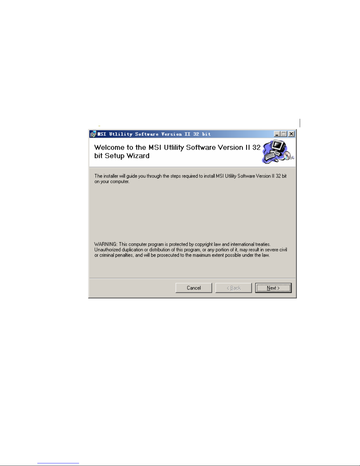
4HOW TO INSTALL UTILITY ....................................................................................................... 5
5HOW TO USE MSI UTILITY SOFTWARE................................................................................ 7
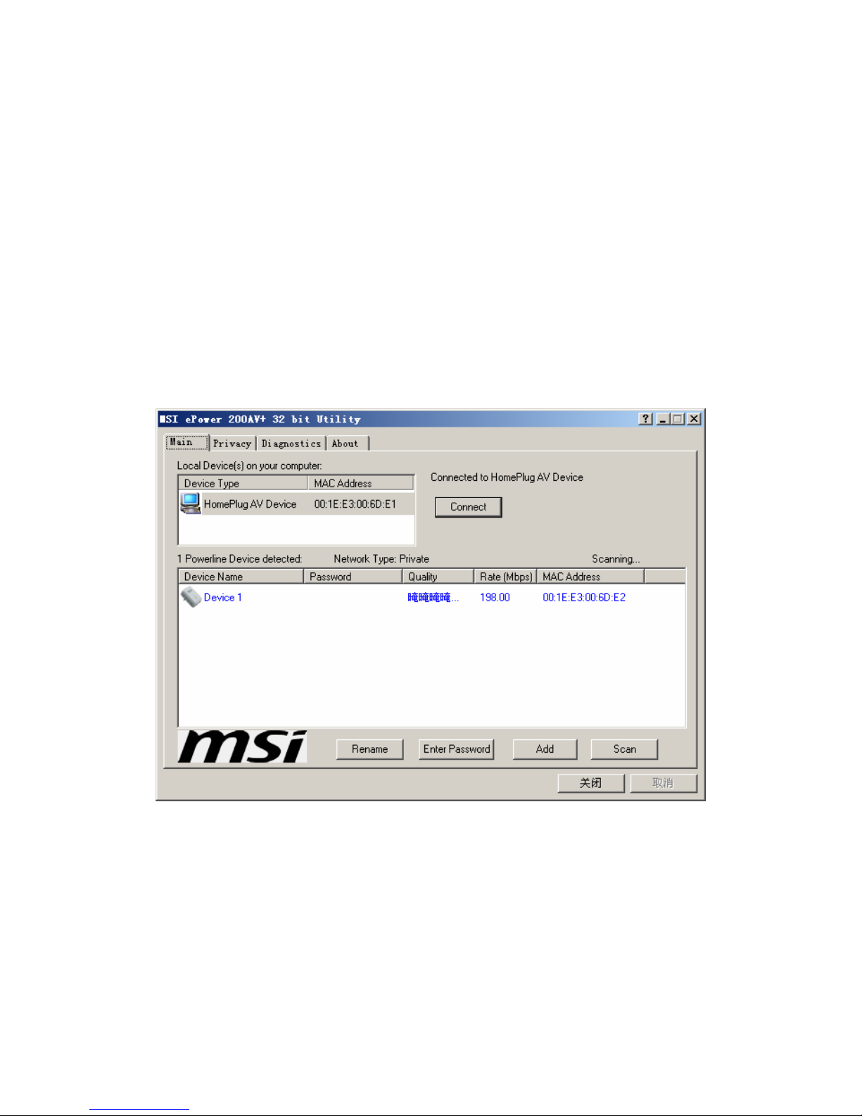
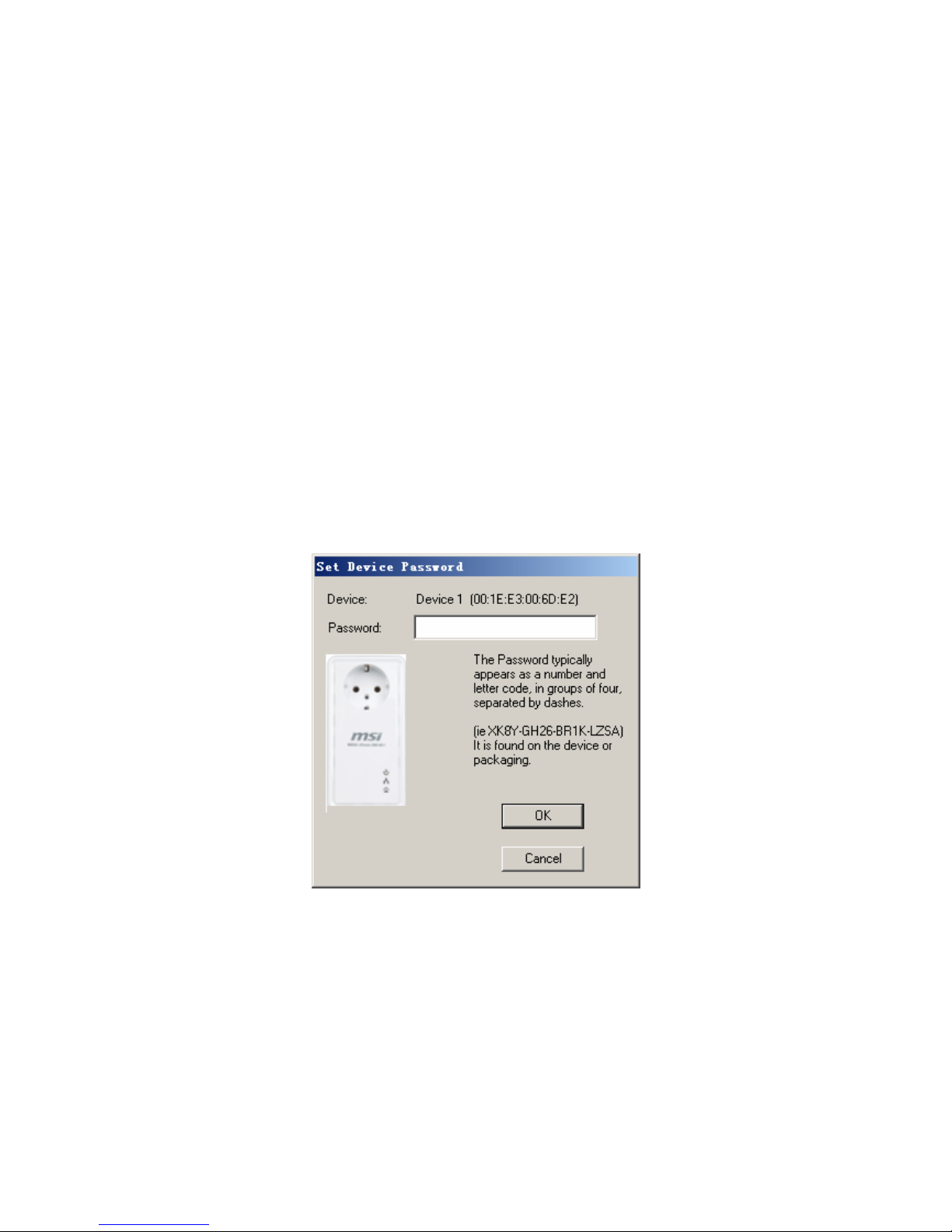
5.1 MAIN TAB.................................................................................................................................7
5.2 PRIVACY TAB......................................................................................................................... 10
5.3 DIAGNOSTICS TAB.................................................................................................................12
5.4 ABOUT TAB ...........................................................................................................................14
6HOW TO USE THE NMK PUSHBUTTON .............................................................................. 15
6.1 FORMING A HOMEPLUG AV LOGICAL NETWORK .................................................................15
6.2 JOINING A NETWORK............................................................................................................. 15
6.3 LEAVING A NETWORK............................................................................................................16
7HOW TO IMPROVE THE TRANSMISSION CAPACITY...................................................... 17
APPENDIX A SPECIFICATIONS ............................................................................................... 18
APPENDIX B ACRONYMS AND ABBREVIATIONS.............................................................. 19
APPENDIX C ABOUT QOS......................................................................................................... 20
APPENDIX D........................................................................................................................................ 21
CONTACT INFORMATION ............................................................................................................... 21

1
MEGA ePower 200AV+ USER MANUAL
1 Introduction
This MEGA ePower 200AV+ (wallmount PLC passthrough product)
transmitting data will up to 200 Mbit/s across the household power line.
And every power socket becomes a connection, and no new wire. You do
not even have to do without an outlet, as this product provides a female
socket to which you can connect your terminal devices or power stripe.
MEGA ePower 200AV+ is suitable for use in a wide range of both
residential (in-home) and commercial (offices, apartments, hotels,
warehouses) network applications. No cables, no drilling. These adapters
enable the effortless creation of a high-speed network that supports video,
voice and data. MEGA ePower 200AV+ in-building an outlet can plug other
electronic devices and suppress the out-band noise which being maken by
them, guaranteeing a very perfect communication quality.
1.1 Product Feature
No new wire, every power socket becomes a connection node in the
household.
Plug-and-play to your routers, computers and other network devices.
Integrating a female socket enables additional terminal devices or power
stripe to be connected to the adapter just as a normal wall socket.
Built-in noise filter splitter significantly improving data transmission.
1.2 Application
zHigh Definition (HD) and Standard Definition (SD) video distribution
zHigher data rate broadband sharing for power line LAN
zShared broadband internet access
zTV over IP (IPTV) and Voice over Internet Protocol (VoIP)

2
Figure 1-1 PLC Application
1.3 System Requirements
Operating System Microsoft Windows 2000 or XP , Vista 32-bit
CPU Intel Pentium III or better, clock rate faster than 2.0GHz
recommended
RAM At least 128MB
Screen Resolution Any resolution
Free Disk Space At least 20MB
Network Interface At least one Fast Ethernet (100 Mbps) network card, and
Ethernet Cord
1.4 Package Contents
MEGA ePower 200AV+ device
(1 device for single pack, 2 devices for duo pack)
CD ROM x 1
RJ45 Ethernet cable
(1 cable for single pack, 2 cables for duo pack)

3
2 Safety Notice:
This device is intended for connection to the AC power line. For installation
instructions, please refer to the installation section of this guide. The following
precautions should be taken when using this product.
Read all instructions before installing and operating this product.
Follow all warnings and instructions marked on the product.
Unplug the device from the wall outlet before cleaning. Use a damp cloth for
cleaning. Do not use liquid cleaners or aerosol cleaners.
Do not operate this product near water.
This product should never be placed near or over a radiator or heat register.
Do not use an extension cord between the device and the AC power source.
Only a qualified technician should service this product. Opening or removing
covers may result in exposure to dangerous voltage points or other risks.
Unplug the device from the wall outlet and refer the product to qualified
service personnel for the following conditions:
If liquid has been spilled into the product
If the product has been exposed to rain or water
If the product does not operate normally when the operating
instructions are followed
If the product exhibits a distinct change in performance

4
3 Getting to Know the Adapter
3.1 The Ethernet Interface
Ethernet : The Ethernet port connects to an Ethernet network cable. The other end of
the cable will connect to your computer or other Ethernet-enabled network device.
3.2 The Adapter's Buttons
RST: The button can restore the factory defaults and reset the device.
NMK: The button is used to set the private network name. The detail see chap 6.
3.3 The Adapter's LEDs
All Adapter's LEDs are located on the front panel, there are 3 LEDs to indicate the
adapter’s status.
Power: Green, the Power LED lights up when the Adapter is powered on.
Ethernet: Green, the Ethernet LED flashes to indicate activity over the Ethernet
connection.
Data: Green, the Data LED flashes to indicate activity over the Powerline
connection.
Figure 3-1 Top view

5
4 How to Install Utility
First step, you need to verify that there is no any other Powerline Utility installed on
your computer before installing this utility. If there is another utility installed, please
uninstall it and restart your computer.
Second step, please insert the Utility CD-ROM into the computer’s CD-ROM drive.
Find the Utility Setup file as below: X:\ ePower 200AV+\SOFTWARE\MSI ePower
200AV+ Utility_EN\Power Packet5.0. Click the setup.exe and the Next button to
continue.
Figure 4-1 Setup Wizard

6
Figure 4-2 Select Installation Folder
Figure 4-3 Installation Complete
Click “Close” to complete installation.

7
5 How to Use MSI Utility Software
5.1 Main Tab
The Main screen provides a list of all Powerline devices logically connected to the
computer when the utility is running.
The top panel shows local HomePlug devices connected to the computer’s NIC
(Network Interface Card). The user can click the Connect button to its right. Once
connected to the local device, the utility will automatically scan the power line
periodically for any other HomePlug devices. If no local HomePlug devices are
discovered, the status area above the connect button will indicate with a message
‘NO HOMEPLUG ADAPTERS DETECTED’.
Figure 5-1: Main Tab information
The lower panel displays all the HomePlug remote devices, discovered on the current
logical network. The total number of remote devices connected on the same network
can be found on top of the Remote device panel. The Network type (Public or Private)
is also displayed based on the network status of the local device. The scan status
option is displayed on the top right corner above the Remote devices panel showing
whether the Autos can functionality is turned ON or OFF. The following information is
displayed for all devices that appear in the lower panel.

8
Device Name
This column shows the default device name, which may be user re-defined. A user
can change the name by either using the rename button or by clicking on the name
and editing in-place.
MAC Address
This column shows the Remote device’s MAC address.
Password
This column by default is blank and “Enter Password” button can be used to enter it.
To set the Password of the device (required when creating a private network), first
select the device by clicking on its name in the lower panel and then click on the Enter
Password button. A dialog box will appear as shown in Figure 5-2 to type the
password. The selected device name is shown above the password field and the
password can be verified by hitting the OK button. The Password field accepts the
Device password in any case formats, with or without dashed between them.
A confirmation box will appear if the password was entered correctly. If a device was
not found, the user will be notified along with the suggestions to resolve common
problems. This process might take a few seconds to get completed.
Figure 5-2: Set Device Password
Add
This button is used to add a remote device to the existing network by entering the
device password of the device. A dialog box will appear as shown below in Figure 6.
The dialog box allows the user to enter both a device name and the password.
A confirmation box will appear if the password was entered correctly and if the device
was found in the Powerline network. If a device was not found, the user will be
notified and suggestions to resolve common problems will be presented.

9
Figure 5-3: Add Remote Device
Note: The device must be present on the power line (plugged in) in order for the
password to be confirmed and added to the network. If the device could not be located, a
warning message will be shown.
Scan
This button is used to perform an immediate search of the HomePlug devices
connected to the Powerline network. By default, the utility automatically scans every
few seconds and updates the display screen.

10
5.2 Privacy Tab
The Privacy screen provides the user with an option to maintain security for their
logical network and also to select the devices that has to be included in the network.
The appearance is shown in Figure 5-4.
All HomePlug devices are shipped using a default logical network (network name),
which is normally “HomePlug”. The Privacy dialog screen allows user to change to a
private network by changing the network name (network password) of devices.
The user can always reset to the HomePlug network (Public) by entering “HomePlug”
as the network name or by clicking on the Use Default button.
Figure 5-4: Privacy Screen
Note: Changing the network name to anything other than HomePlug will show the
network type on the main screen as Private.
Set Local Device Only
This button can be used to change the network name (network password) of the local
device. If a new network password is entered, all the devices seen on the Main panel
prior to this will be no longer present in the new network, effectively making the local
devices not to communicate to the devices that were in the old logical network.
Devices previously set up with the same logical network (same network name) will
appear in the device list afterward selecting this option.

11
Set All Devices
This button is used to change the logical network of all devices that appear on the
Main panel whose Device’s Password had been entered for the same logical network.
A dialog window will appear to report the success of this operation. For devices
whose device password’s were not entered, this operation will fail and will report a
failure message.

12
5.3 Diagnostics Tab
The Diagnostics screen shows System information and a history of all remote devices
seen over a period of time. The appearance is shown in Figure 5-5.
The Upper panel shows technical data concerning software and hardware present on
the host computer which were used to communicate over HomePlug on the
Powerline network. It shall include the following:
Operating System Platform/Version
Host Network Name
User Name
MAC Address of all NICs (Network interface card) connected to the host
Identify versions of all Driver DLLs and Libraries used (NDIS) and optionally
HomePlug chipset manufacturer name (Turbo Only devices)
MAC Firmware Version (Turbo Only devices)
MAC addresses of all devices connected locally to the host
Version of the Configuration Utility
Vendor name
Figure 5-5: Diagnostics Screen
The Lower panel contains a history of all remote devices seen on the computer over a
certain period of time. All devices that were on the Powerline network are listed here
along with a few other parameters. Devices that are active on the current logical
network will show a transfer rate in the Rate column; devices on other networks, or
devices that may no longer exist are shown with a “?” in the Rate column. The

13
following remote device information is available from the diagnostics screen:
Device Alias Name
Device MAC Address
Device Password
Device Last known rate
Device Last Known Network name
HomePlug chipset manufacturer name
Date device last seen on the network
MAC Firmware Version
The diagnostics information displayed may be saved to a text file for later use, or can
be printed for reference for a technical support call. Devices, which are not part of the
network anymore, can be deleted using the delete button. A dialog window pops up
with a confirmation message if we try to delete a device whose password has been
entered.

14
5.4 About Tab
The About screen shows the software version and provides an html link to the MSI
website. Clicking on the web address field will open a web browser and take the user
directly to the web site.
Figure 5-6: About Dialog Tab
Preferences
The lower part of the panel may display options for turning the auto-scan feature on
or off.

15
6 How to use the NMK Pushbutton
This section describes how to add new devices to, or remove old devices from a
HomePlug AV logical network(AVLN), both can be accomplished using a NMK
pushbutton press.
Operation progress and outcome can be monitored by observing the behavior of the
Power LED.
6.1 Forming a HomePlug AV logical network
When two devices with different NMK values are connected to the same powerline,
and wants them to form a logical network.
1. Press the NMK button on the first device A for less than 3 seconds.
2. Press the NMK button on the second device B for less than 3 seconds. The
button on B must be pressed within 1 minute
3. Wait for connection to complete.
The Power LED on both devices will flash evenly at 1-second intervals until the
operation succeeds or fails. It will illuminate steadily on successful completion. If an
error occurs, the Power LED on the ‘adder’ will flash unevenly until the pushbutton on
the ‘adder’ is pressed again or the ‘joiner’ is reset by holding the pushbuttons down
for more than 10 seconds.
A
PLC
B
PLC
C
PLC
A and B are not part of AVLN
A and B want to form an AVLN
Press NMK button on A less than 3 sec.
Press NMK button on B less than 3 sec.
A becomes “joiner”
B becomes “joiner”
B determines that A MAC address < B MAC address
B becomes “adder”
A accepts NMK from B
A
PLC
A
PLC
B
PLC
B
PLC
C
PLC
A and B are not part of AVLN
A and B want to form an AVLN
Press NMK button on A less than 3 sec.
Press NMK button on B less than 3 sec.
A becomes “joiner”
B becomes “joiner”
B determines that A MAC address < B MAC address
B becomes “adder”
A accepts NMK from B
Figure 6-1: Forming a HomePlug AV logical network
6.2 Joining a Network
In this scenario a network exists, a new device, the ‘joiner’, wants to join the network.
Any device on the existing network can become the ‘adder’.
1. Press the pushbutton on the ‘joiner’ for at least 3 seconds.
2. Press the pushbutton on any network device for less than 3 seconds, making
it the ‘adder’. Please press this pushbutton within 1 minute.
3. Wait for connection to complete.
The Power LED on both devices will flash at 1-second intervals until the process

16
succeeds or fails. It will illuminate steadily on success. If an error occurs, the Power
LED on the ‘adder’ will flash unevenly until the pushbutton on the ‘adder’ is pressed
again or the ‘joiner’ is reset by pressing the pushbutton for more than 10 seconds.
A
PLC
B
PLC
C
PLC
A and B form an AVLN
C wants to join the AVLN
Press NMK button on B less than 3 sec.
Press NMK button on C less than 3 sec.
B becomes “adder”
C becomes “joiner”
C accepts NMK from B
A
PLC
A
PLC
B
PLC
B
PLC
C
PLC
A and B form an AVLN
C wants to join the AVLN
Press NMK button on B less than 3 sec.
Press NMK button on C less than 3 sec.
B becomes “adder”
C becomes “joiner”
C accepts NMK from B
Figure 6-2: Joining a Network
6.3 Leaving a Network
A network exists. The user wants to remove one device, the ‘leaver’, from that
network, for whatever reason. He may want to remove the device from service
altogether or have it join another logical network.
1. Press the pushbutton on the ‘leaver’ for at least 10 seconds. The device will
reset and restart with a random NMK.
2. Wait for reset to complete.
The Power LED on the ‘leaver’ will momentarily extinguish during reset, flash during
restart then illuminate steadily. No errors can occur.
Once the process completes, the user may disconnect the device from the medium or
join it to another logical network on the same medium.
A
PLC
B
PLC
C
PLC
A, B and C form an AVLN
A wants to leave the AVLN
Press NMK button on A more than 10 sec.
A computes random NMK
A resets and restarts
A
PLC
A
PLC
B
PLC
B
PLC
C
PLC
A, B and C form an AVLN
A wants to leave the AVLN
Press NMK button on A more than 10 sec.
A computes random NMK
A resets and restarts
Figure 6-3: leaving a Network

17
7 How to Improve the Transmission Capacity
It is important to use the PLC product complying with the following "correct rules",
because it can significantly improve the transmission capacity of the network.
For the PLC device no female socket, it is recommended to plug the device directly
into a wall socket, not to power stripe.
×
√×
√
For the PLC device with female socket, you should connect all additional network
devices that are connected to a multiple socket to the mains power supply via the
electrical socket integrated into the PLC device with female socket. To take full
advantage of the filter function, to improve data transmission in the network, always
plug the power stripe into the female socket.

18
Appendix A Specifications
Chipset Intellon INT6400/INT1400
Protocol HomePlug AV 1.0
Co-exists with existing HomePlug 1.0
System Support Windows 98SE, 2000, ME, XP 32/64 bit and Vista 32/64bit
PLC Rate 200Mb
Modulation Band 2-30MHz
Modulation Schemes Supports1024/256/64/16/8-QAM, QPSK,BPSK and ROBO
Encryption 128 AES
Outlet current 220VAC 16A Maximum,110VAC 20A Maximum
Filter characteristics -22 dB to -45 dB
LED’s Power
Ethernet: Ethernet Link and Activity
Data: PLC Link and Activity
Push Button Reset: Restore the default factory parameter
Security: Set up network password automatically
Consumption 3.5W
Operating Temperature 0º to 45º C
Storage Temperature -20 º to 70 º C
Operating Humidity 10% to 90% Non-condensing
Storage Humidity 5% to 90% Non-Condensing
Input Rating 100-240 VAC, 50/60Hz
Certifications CE, UL, FCC Part 15 Class B
Green Standard RoHS
Physical Characteristics L×W×H: 130.5mm×69mm×79mm
Weight 233g
Table of contents
Other MSI Adapter manuals