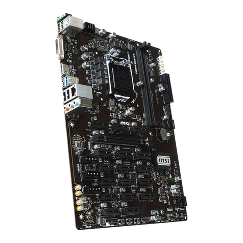
MSI MS-CF05-SKU1 User manual

MS-CF05
Industrial Computer Board
User Guide
SKU1 (Intel® R680E)
SKU2 (Intel® Q670E)

2Contents
Revision
V1.0, 2023/08
Contents
Regulatory Notices....................................................................................................... 5
Safety Information........................................................................................................ 8
Specifications................................................................................................................ 9
Motherboard Overview............................................................................................... 12
SKU1 ...................................................................................................................... 12
SKU2 ...................................................................................................................... 13
Rear I/O Panel............................................................................................................. 14
SKU1 ...................................................................................................................... 14
SKU2 ...................................................................................................................... 14
DisplayPort ............................................................................................................ 15
Connector ....................................................................................... 15
RS232/422/485 Serial Port .................................................................................... 15
VGA Port................................................................................................................. 15
2.5 GbE RJ-45 LAN Jacks...................................................................................... 16
USB 3.2 Gen 2 Ports .............................................................................................. 16
Line-Out Jack ........................................................................................................ 16
Mic-In Jack ............................................................................................................ 16
CPU Socket ................................................................................................................. 18
Introduction to the LGA1700 CPU ..................................................................................................... 18
CPU & Heatsink Installation.................................................................................. 19
Memory ....................................................................................................................... 20
DIMM1~2: DDR5 DIMM Slots ............................................................................................................20
Recommended Memory Population .................................................................................................20
Installing Memory Modules ..............................................................................................................21
Storage........................................................................................................................ 22
SATA1_2, 3_4: SATA 3.0 6Gb/s Connectors...................................................................................... 22
Expansion Slots .......................................................................................................... 23
PCIe Slots .............................................................................................................. 23
PCIE1~7: PCIe Expansion Slots ........................................................................................................23

3
Contents
M.2 Slots ................................................................................................................ 24
M2_M1: M.2 Slot (M Key, PCIe 4.0 x4, 2280/ 22110) ......................................................................... 24
M2_M2: M.2 Slot (M Key, PCIe 4.0 x4/x2/x1, 2242/ 2280)................................................................. 24
M2_E1: M.2 Slot (E Key, 2230) (SKU1 Only)...............................................................................25
M2_B1: M.2 Slot (B Key, 2242/ 2280) (SKU1 Only) .....................................................................25
Connectors.................................................................................................................. 26
Power Connectors ................................................................................................. 26
JPWR1: 24-Pin ATX Power Connector.............................................................................................. 26
JPWR2: 8-Pin ATX 12V Power Connector.........................................................................................26
Cooling Connectors ............................................................................................... 27
CPUFAN1, SYSFAN1~3: CPU/ System Fan Connectors .................................................................. 27
Audio Connectors .................................................................................................. 28
JAUD1: Front Audio Connector (Line-out/ MIC-in)..........................................................................28
JSPDIF1: S/PDIF Connector..............................................................................................................28
USB Connectors .................................................................................................... 29
JUSB2: USB 3.2 Gen 1 Connector..................................................................................................... 29
JUSB1: USB 2.0 Connector ............................................................................................................... 30
USB1: USB 2.0 Type-A Connector.....................................................................................................30
Other Connectors .................................................................................................. 31
JFP1: Front Panel Connector...........................................................................................................31
JGPIO1: GPI Connector .....................................................................................................................31
JGPIO2: GPO Connector.................................................................................................................... 31
JPMBUS1: PMBus Connector ..........................................................................................................32
JSMB1: I2C Connector ..................................................................................................................... 32
JI2C1: SMBus Connector ................................................................................................................. 32
COM2~6: Serial Port Connectors...................................................................................................... 33
JLAN_LED: LAN LED Connector ......................................................................................................35
JKBMS1: PS/2® Keyboard & Mouse Connector................................................................................35
JLPT1: Parallel Port Connector........................................................................................................36
Jumpers ...................................................................................................................... 37
BIOS Setup .................................................................................................................. 39
Entering Setup....................................................................................................... 39
The Menu Bar ............................................................................................................. 41

4Contents
Main ............................................................................................................................. 42
Advanced..................................................................................................................... 43
Boot.............................................................................................................................. 50
Security........................................................................................................................ 51
Chipset......................................................................................................................... 59
Power .......................................................................................................................... 60
Save & Exit .................................................................................................................. 61
GPIO WDT BKL Programming .................................................................................. 62
Abstract ................................................................................................................. 62
General Purpose IO ............................................................................................... 63
Watchdog Timer .................................................................................................... 65
SMBus Access ....................................................................................................... 67

5
Regulatory Notices
Regulatory Notices
FCC-B Radio Frequency Interference Statement
This equipment has been tested and found to comply with the limits
for a Class B digital device, pursuant to part 15 of the FCC rules. These
limits are designed to provide reasonable protection against harmful
interference in a residential installation. This equipment generates,
uses and radiates radio frequency energy, and, if not installed and
used in accordance with the instructions, may cause harmful interference to radio
communications. However, there is no guarantee that interference will not occur in a
particular installation. If this equipment does cause harmful interference to radio or
television reception, which can be determined by turning the equipment off and on, the
user is encouraged to try to correct the interference by one or more of the following
measures:
∙Reorient or relocate the receiving antenna.
∙Increase the separation between the equipment and receiver.
∙Connect the equipment into an outlet on a circuit different from that to which the
receiver is connected.
NOTE
∙The changes or modifications not expressly approved by the party responsible for
compliance could void the user’s authority to operate the equipment.
∙Shield interface cables and AC power cord, if any, must be used in order to comply
with the emission limits.
FCC Conditions
This device complies with part 15 of the FCC Rules. Operation is subject to the
following two conditions:
∙This device may not cause harmful interference.
∙This device must accept any interference received, including interference that may
cause undesired operation.
CE Conformity
Hereby, Micro-Star International CO., LTD declares that this device is in
compliance with the essential safety requirements and other relevant
provisions set out in the European Directive.
WEEE Statement
Under the European Union (“EU”) Directive on Waste Electrical and
Electronic Equipment, Directive 2012/19/EU, products of “electrical and
electronic equipment” cannot be discarded as municipal waste anymore
and manufacturers of covered electronic equipment will be obligated to
take back such products at the end of their useful life.

6Contents
Battery Information
Please take special precautions if this product comes with a battery.
∙Danger of explosion if battery is incorrectly replaced. Replace only with the same or
equivalent type recommended by the manufacturer.
∙Avoid disposal of a battery into fire or a hot oven, or mechanically crushing or
cutting of a battery, which can result in an explosion.
∙Avoid leaving a battery in an extremely high temperature or extremely low air
pressure environment that can result in an explosion or the leakage of flammable
liquid or gas.
∙Do not ingest battery. If the coin/button cell battery is swallowed, it can cause
severe internal burns and can lead to death. Keep new and used batteries away
from children.
European Union:
Batteries, battery packs, and accumulators should not be disposed of as
unsorted household waste. Please use the public collection system to
return, recycle, or treat them in compliance with the local regulations.
BSMI:
廢電池請回收
For better environmental protection, waste batteries should be collected
separately for recycling or special disposal.
California, USA:
The button cell battery may contain perchlorate material and requires
special handling when recycled or disposed of in California.
For further information please visit:
http://www.dtsc.ca.gov/hazardouswaste/perchlorate/
Chemical Substances Information
In compliance with chemical substances regulations, such as the EU REACH
Regulation (Regulation EC No. 1907/2006 of the European Parliament and the
Council), MSI provides the information of chemical substances in products at:
https://csr.msi.com/global/index
Environmental Policy
∙The product has been designed to enable proper reuse of parts and
recycling and should not be thrown away at its end of life.
∙Users should contact the local authorized point of collection for recycling
and disposing of their end-of-life products.
∙Visit the MSI website and locate a nearby distributor for further recycling
information.
∙Users may also reach us at [email protected] for information regarding proper
Disposal, Take-back, Recycling, and Disassembly of MSI products.

7
Contents
Green Product Features
∙Reduced energy consumption during use and stand-by
∙Limited use of substances harmful to the environment and health
∙Easily dismantled and recycled
∙Reduced use of natural resources by encouraging recycling
∙Extended product lifetime through easy upgrades
∙Reduced solid waste production through take-back policy
Copyright and Trademarks Notice
Copyright © Micro-Star Int’l Co., Ltd. All rights reserved. The MSI logo used is
a registered trademark of Micro-Star Int’l Co., Ltd. All other marks and names
mentioned may be trademarks of their respective owners. No warranty as to accuracy
or completeness is expressed or implied. MSI reserves the right to make changes to
this document without prior notice.
The terms HDMI™, HDMI™ High-Definition Multimedia Interface, HDMI™ Trade dress
and the HDMI™ Logos are trademarks or registered trademarks of HDMI™ Licensing
Administrator, Inc.
Technical Support
If a problem arises with your product and no solution can be obtained from the user’s
manual, please contact your place of purchase or local distributor. Alternatively,
please visit https://www.msi.com/support/ for further guidance.

8Safety Information
Safety Information
∙The components included in this package are prone to damage from electrostatic
discharge (ESD). Please adhere to the following instructions to ensure successful
computer assembly.
∙Ensure that all components are securely connected. Loose connections may cause
the computer to not recognize a component or fail to start.
∙Hold the motherboard by the edges to avoid touching sensitive components.
∙It is recommended to wear an electrostatic discharge (ESD) wrist strap when
handling the motherboard to prevent electrostatic damage. If an ESD wrist strap
is not available, discharge yourself of static electricity by touching another metal
object before handling the motherboard.
∙Store the motherboard in an electrostatic shielding container or on an anti-static
pad whenever the motherboard is not installed.
∙Before turning on the computer, ensure that there are no loose screws or metal
components on the motherboard or anywhere within the computer case.
∙Do not boot the computer before installation is completed. This could cause
permanent damage to the components as well as injury to the user.
∙If you need help during any installation step, please consult a certified computer
technician.
∙Always turn off the power supply and unplug the power cord from the power outlet
before installing or removing any computer component.
∙Keep this user guide for future reference.
∙Keep this motherboard away from humidity.
∙Make sure that your electrical outlet provides the same voltage as is indicated on
the PSU, before connecting the PSU to the electrical outlet.
∙Place the power cord such a way that people can not step on it. Do not place
anything over the power cord.
∙All cautions and warnings on the motherboard should be noted.
∙If any of the following situations arises, get the motherboard checked by service
personnel:
• Liquid has penetrated into the computer.
• The motherboard has been exposed to moisture.
• The motherboard does not work well or you can not get it work according to user
guide.
• The motherboard has been dropped and damaged.
• The motherboard has obvious sign of breakage.
∙Do not leave this motherboard in an environment above 60°C (140°F), it may damage
the motherboard.

Specifications
Model MS-CF05-SKU1 MS-CF05-SKU2
Dimensions 305(L)mm x 244(W)mm x 1.6(H)mm, ATX-Size
Processor
∙13th Gen Intel® Raptor Lake-S
i9/i7/i5/i3 Pentium®/ Celeron® IOTG Series Processor, Max 125W
∙12th Gen Intel® Alder Lake-S
i9/i7/i5/i3 Pentium®/ Celeron® IOTG Series Processor, Max 125W
Chipset Intel® R680E Intel® Q670E
Memory
∙4 x DDR5 UDIMM slots (288-pin, vertical)
-Up to 4400 MT/s
-Up to 128GB
-Dual-Channel DDR5, ECC/ Non-ECC -Dual-Channel DDR5, Non-ECC
Network ∙4 x Intel® I225-LM PCIe 2.5GbE LAN
-LAN1: Supports iAMT 16.X
∙2x Intel® I225-LM PCIe 2.5GbE LAN
-LAN1: Supports iAMT 16.X
Expansion
Slots
∙2 x PCIe 5.0 x16 slots (PCIE1, 4*)
∙1 x PCIe 4.0 x4 slot (PCIE5**)
∙3 x PCIe 3.0 x4 slots (PCIE3, 6, 7)
∙1 x PCIe 3.0 x1 slot (PCIE2)
∙1 x M.2 M Key slot (M2_M1, 2280/ 22110)
-Supports PCIe 4.0 x4 NVMe signal
-Supports B+M Key module
∙1 x M.2 M Key slot (M2_M2, 2242/ 2280)
-Supports PCIe 4.0 x4/x2/x1 NVMe signal
-Signal shared by PCIE5
-Supports B+M Key module
∙1 x M.2 B Key slot (2242/ 2280)
-Supports PCIe 3.0 x1 signal
-Supports Innodisk devices:
EGP2-X401-W1, EGPL-G202-W1,
EGPL-G2S1
-Supports PCIe 3.0 x2 NVMe SSD***
(Optional by request)
∙1 x M.2 E Key slot (2230)
-Supports PCIe x1 signal
-Supports Intel® AX210 Wi-Fi 6E (BT
not supported), Intel® Wireless-AC
9260 (BT not supported)
∙2 x PCIe 5.0 x16 slots (PCIE1, 4*)
∙1 x PCIe 4.0 x4 slot (PCIE5**)
∙3 x PCIe 3.0 x4 slots (PCIE3, 6, 7)
∙1 x M.2 M Key slot (M2_M1, 2280/ 22110)
-Supports PCIe 4.0 x4 NVMe signal
-Supports B+M Key module
∙1 x M.2 M Key slot (M2_M2, 2242/ 2280)
-Supports PCIe 4.0 x4/x2/x1 NVMe signal
-Signal shared by PCIE5
-Supports B+M Key module
* When the PCIE1 slot is occupied, it will operate at 5.0 x16 speed, while the PCIE4 slot will not
be available. Both PCIE1,4 slots will run at 5.0 x8 speed when occupied.
** It is necessary to remove the M.2 screw when installing a PCIe x8 or x16 card in PCIE5.
*** The HDD LED cannot be enabled when installing PCIe 3.0 x2 NVMe SSD in M2_B1.
Storage
∙4 x SATA 3.0 6Gb/s connectors
-Support RAID 0/1/5
-Support AHCI mode
Audio ∙Realtek® ALC897 High Definition Audio Codec
Continued on next column
9
Specifications
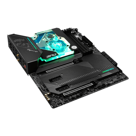
Model MS-CF05-SKU1 MS-CF05-SKU2
Graphics
∙1 x DP 1.4a, up to 4096×2304 @60Hz
∙1 x HDMI™ 2.0b, up to 4096x2160 @60Hz
∙1 x VGA, up to 1920x1200 @60Hz
∙3 independent display modes supported
-DP
-HDMI™
-VGA
Rear I/O
∙1 x DisplayPort (1.4a)
∙1 x HDMI™ connector (2.0b)
∙1 x VGA port
∙1 x DB-9 RS-232/422/485 serial port
-COM1: Ring/0V/5V/12V (default set to Ring), Auto-flow Control supported
∙1 x Line-out jack
∙1 x Mic-in jack
∙8x USB 3.2 Gen 2 Type-A ports (10 Gbps)
∙4x 2.5 GbE RJ-45 LAN ports ∙2x 2.5 GbE RJ-45 LAN ports
Onboard
Connector
∙1 x 4-pin PWM CPU fan connector
∙3 x 4-pin PWM system fan connectors
∙1 x Front Audio connector (Line-out & Mic-in)
∙1 x S/PDIF connector
∙1 x USB 3.2 Gen 1 connector (JUSB2)
∙1 x USB 2.0 connector (JUSB1)
∙1 x USB 2.0 Type-A connector (USB1)
∙1 x Front panel connector
∙1 x GPI connector
∙1 x GPO connector
∙1 x PMBus connector
∙1 x I2C connector
∙1 x SMBus connector
∙5 x Serial port connectors
∙1 x LAN LED connector
∙1 x PS/2® Keyboard & Mouse Connector
∙1 x M.2 PCIE Signal Select Jumper
∙6 x COM voltage select jumpers
∙1 x AT/ ATX mode select jumper
∙1 x ME jumper
∙1 x Clear CMOS jumper
∙1 x Chassis Intrusion jumper
Continued on next column
10 Specifications
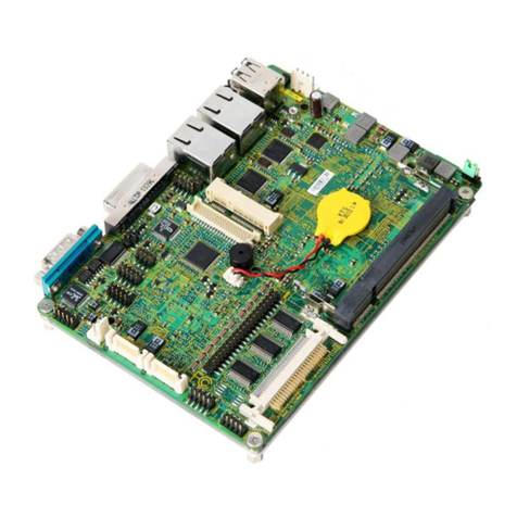
Model MS-CF05-SKU1 MS-CF05-SKU2
Power ∙1 x 24-pin ATX power connector
∙1 x 4-pin 12V ATX power connector
OS Support
∙Windows 10 IoT Enterprise 2021 LTSC (64-bit)
∙Windows 11 IoT Enterprise 22H2 LTSC (64-bit)
∙Linux Kernel 5.xx, Ubuntu 22.04 LTS Pre-scan
Certification CE, FCC Class B, BSMI, RCM, VCCI, UKCA
Environment
∙Operating Temperature: 0 ~ 60°C
∙Storage Temperature: -20 ~ 80°C
∙Relative Humidity: 10 ~ 90%, non-condensing
11
Specifications
Motherboard Overview
SKU1
JPWR1
JUSB2
M2_M1
SATA3_4
SATA1_2
JLAN_LED
JFP1
M2_M2
M2_B1
M2_E1
JUSB1
USB1
Rear
I/O Panel
JPWR2 CPUFAN1
DIMMA1
DIMMA2 DIMMB2
DIMMB1
JPMBUS1
SYSFAN2
JSMB1
JI2C1
SYSFAN1
SYSFAN3
JGPIO1JGPIO2JAPS1COM2COM3COM4COM5COM6JLPT1
JAUD1
JSPDIF1
PCIE7
PCIE6
PCIE5
PCIE4
PCIE3
PCIE2
PCIE1
JKBMS1
J_PCIE_SEL
JCOMP1
JCOMP4
JCOMP2
JCOMP3
JATX1
JME_DIS1
JCOMS1
JCOMP6
JCOMP5
JCASE1
1
2
345
6
789
10
11
1
2
6
9
8
4
7
3
5
10
11
12 Motherboard Overview

SKU2
JPWR1
JUSB2
M2_M1
SATA3_4
SATA1_2
JLAN_LED
JFP1
M2_M2
JUSB1
USB1
Rear
I/O Panel
JPWR2 CPUFAN1
DIMMA1
DIMMA2 DIMMB2
DIMMB1
JPMBUS1
SYSFAN2
JSMB1
JI2C1
SYSFAN1
SYSFAN3
JGPIO1JGPIO2JAPS1COM2COM3COM4COM5COM6JLPT1
JAUD1
JSPDIF1
PCIE7
PCIE6
PCIE5
PCIE4
PCIE3
PCIE1
JCOMP1
JCOMP2 JCOMP3
JCOMP6
JME_DIS1
JATX1
JCOMS1
JCOMP5
JCASE1
JCOMP4
JKBMS1
1
234 6
57 8
9
10
1
2
6
9
8
4
7
3
510
13
Motherboard Overview

Rear I/O Panel
SKU1
LAN3 LAN4
USB 3.2 Gen 2 Ports
VGA Port
Line-Out
Jack
Mic-in
Jack
2.5 GbE
RJ-45 LAN Jacks
DisplayPort
RS232/422/485
Serial Port
LAN2LAN1
SKU2
USB 3.2 Gen 2 Ports
VGA Port
Line-Out
Jack
Mic-in
Jack
2.5 GbE
RJ-45 LAN Jacks
DisplayPort
RS232/422/485
Serial Port
LAN2LAN1
14 Rear I/O Panel

DisplayPort
DisplayPort is a digital display interface standard. This connector is used to connect a
monitor with DisplayPort inputs.
Connector
The High-Definition Multimedia Interface (HDMI™) is an all-digital audio/ video
interface capable of transmitting uncompressed streams. HDMI™ supports all TV
format, including standard, enhanced, or high-definition video, plus multi-channel
digital audio on a single cable.
RS232/422/485 Serial Port
The serial port is a 16550A high speed communications port that sends/receives 16
bytes FIFOs. It supports barcode scanners, barcode printers, bill printers, credit card
machine, etc.
1155
6699
RS232
PIN SIGNAL DESCRIPTION
1
2
3
4
5
6
7
8
9
NDCD
NSIN
NSOUT
NDTR
GND
NDSR
NRTS
NCTS
VCC_COM
Data Carrier Detect
Signal In
Signal Out
Data Terminal Ready
Signal Ground
Data Set Ready
Request To Send
Clear To Send
VCC_COM
RS422
PIN SIGNAL DESCRIPTION
1
2
3
4
5
6
7
8
9
422 TXD-
422 TXD+
422 RXD+
422 RXD-
GND
NC
NC
NC
NC
Transmit Data, Negative
Transmit Data, Positive
Receive Data, Positive
Receive Data, Negative
Signal Ground
No Connection
No Connection
No Connection
No Connection
RS485
PIN SIGNAL DESCRIPTION
1
2
3
4
5
6
7
8
9
TXD-
NC
TXD+
NC
GND
NC
NC
NC
NC
Transmit Data, Negative
No Connection
Transmit Data, Positive
No Connection
Signal Ground
No Connection
No Connection
No Connection
No Connection
VGA Port
The VGA port supports monitors and other VGA interface devices.
15
Rear I/O Panel

2.5 GbE RJ-45 LAN Jacks
The standard single RJ45 LAN jack is provided for connection to the Local Area
Network (LAN). You can connect a network cable to it.
Link/ Activity LED
Status Description
Off No link
Yellow Linked
Blinking Data activity
Speed LED
Status Description
Off 10/100 Mbps
Green 1000 Mbps
Orange 2.5 Gbps
USB 3.2 Gen 2 Ports
USB 3.2 Gen 2, the SuperSpeed USB 10Gbps, delivers high-speed data transfer for
various devices, such as storage devices, hard drives, video cameras, etc.
Line-Out Jack
This connector is provided for headphones or speakers.
Mic-In Jack
This connector is provided for microphones.
16 Rear I/O Panel

Component Contents
Component Page
CPU Socket 18
Memory 20
DIMM1~2: DDR5 DIMM Slots 20
Storage 22
SATA1_2, 3_4: SATA 3.0 6Gb/s Connectors 22
Expansion Slots 23
PCIE1~7: PCIe Expansion Slots 23
M2_M1: M.2 Slot (M Key, PCIe 4.0 x4, 2280/ 22110) 24
M2_M2: M.2 Slot (M Key, PCIe 4.0 x4/x2/x1, 2242/ 2280) 24
M2_E1: M.2 Slot (E Key, 2230) (SKU1 Only) 25
M2_B1: M.2 Slot (B Key, 2242/ 2280) (SKU1 Only) 25
Connectors 26
Power Connectors 26
JPWR1: 24-Pin ATX Power Connector 26
JPWR2: 8-Pin ATX 12V Power Connector 26
Cooling Connectors 27
CPUFAN1, SYSFAN1~3: CPU/ System Fan Connectors 27
Audio Connectors 28
JAUD1: Front Audio Connector (Line-out/ MIC-in) 28
JSPDIF1: S/PDIF Connector 28
USB Connectors 29
JUSB2: USB 3.2 Gen 1 Connector 29
JUSB1: USB 2.0 Connector 30
USB1: USB 2.0 Type-A Connector 30
Other Connectors 31
JFP1: Front Panel Connector 31
JGPIO1: GPI Connector 31
JGPIO2: GPO Connector 31
JPMBUS1: PMBus Connector 32
JSMB1: I2C Connector 32
JI2C1: SMBus Connector 32
COM2~6: Serial Port Connectors 33
JLAN_LED: LAN LED Connector 35
JKBMS1: PS/2® Keyboard & Mouse Connector 35
JLPT1: Parallel Port Connector 36
Jumpers 37
17
Component Contents

⚠
Important
∙
Always unplug the power cord from the power outlet before installing or removing
the CPU.
∙
When installing a CPU, always remember to install a CPU heatsink. A CPU heatsink
is necessary to prevent overheating and maintain system stability.
∙
Confirm that the CPU heatsink has formed a tight seal with the CPU before booting
your system.
∙
Overheating can seriously damage the CPU and motherboard. Always make sure
the cooling fans work properly to protect the CPU from overheating. Be sure to
apply an even layer of thermal paste (or thermal tape) between the CPU and the
heatsink to enhance heat dissipation.
∙
Whenever the CPU is not installed, always protect the CPU socket pins by covering
the socket with the plastic cap.
∙
If you purchased a separate CPU and heatsink/ cooler, Please refer to the
documentation in the heatsink/ cooler package for more details about installation.
CPU Socket
Introduction to the LGA1700 CPU
The surface of the LGA1700 CPU has four
notches and a golden triangle to assist in
correctly lining up the CPU for motherboard
placement. The golden triangle is the Pin 1
indicator.
18 CPU Socket

CPU & Heatsink Installation
Use appropriate ground straps, gloves and ESD mats to protect yourself from
electrostatic discharge (ESD) while installing the processor.
⚠
Important
Images are for illustration purposes only; actual parts may vary.
11
22
33
44
55
66
77
88
99
⚽
https://youtu.be/KMf9oIDsGes
19
CPU Socket

Memory
DIMM1~2: DDR5 DIMM Slots
The DIMM slots are intended for memory modules.
Recommended Memory Population
Quantity of DIMMs 1 2 3 4
Channel A DIMMA1 V V V
DIMMA2 V V V V V V
Channel B DIMMB1 V V V
DIMMB2 V V V V V
**“V” indicates a populated DIMM slot. **
⚠
Important
∙
Only support UDIMM.
∙
There should be at least 1 DDR5 DIMM populated.
∙
Paired memory installation for Max performance.
∙
If only 1 DIMM is populated in a channel, then populate it in the DIMMA2 slot.
∙
Populate the same DIMM type in each channel, specifically: 1. Use the same DIMM
size; 2. Use the same number of ranks per DIMM.
∙
We don’t suggest other memory installation.
DIMMA1 DIMMB1
Channel A Channel B
DIMMA2 DIMMB2
20 Memory
This manual suits for next models
1
Table of contents
Other MSI Computer Hardware manuals

MSI
MSI MAG CORELIQUID M360 User manual

MSI
MSI MAG CORELIQUID C360 User manual

MSI
MSI MS-CF03 User manual

MSI
MSI P6N SLI Platinum series User manual

MSI
MSI 919-98E2-001 User manual

MSI
MSI SLI BRIDGE KIT User manual

MSI
MSI MS-98C7 User manual

MSI
MSI MPG X570S Carbon EK X User manual

MSI
MSI HMI 2.0 User manual

MSI
MSI P55-GD61 Series User manual