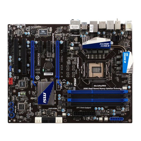
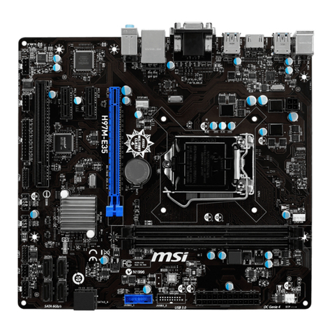
MSI MS-7502 Series User manual

1-1
Getting Started
Getting Started
Chapter1
ThankyouforchoosingtheMS-7502SeriesMicro-ATX
mainboard. The MS-7502Seriesmainboardsarebased
on Intel G33&ICH9DH chipsetsforoptimal system
efficiency.Designedtofittheadvanced Intel Core2
Quad/Core2Duo/Dual-Core(E2xxx)LGA775
processor,the MS-7502 Seriesdeliverahighperfor-
manceandprofessionaldesktopplatformsolution.

MS-7502Mainboard
1-2
MainboardSpecifications
ProcessorSupport
-Intel Core2Quad/Core2Duo/Dual-Core(E2xxx)processorsinthe
LGA775 package
SupportedFSB
-1333/1066/800 MHz
Chipset
-NorthBridge:Intel G33chipset
-SouthBridge: Intel ICH9DHchipset
MemorySupport
-DDR2800/ 667SDRAM(8GBMax)
-4DDR2DIMMs(240pin/1.8V)
LAN
-SupportsPCIELAN10/100FastEthernetbyIntel82562V
Audio
-ChipintegratedbyRealtek ALC888S
-Flexible8-channelaudiowithjacksensing
-Supports2SPDIF-out(coaxial& optical)
-CompliantwithAzalia1.0Spec
-MeetMicrosoft VistaPremiumspec
SATA
-6SATAIIportsbyICH9DH
-Supportsstorageanddatatransfersatupto300MB/s
1394
-Supports1394byVIAVT6308
FDD
-1floppyport
-Supports1FDD with360KB, 720KB,1.2MB,1.44MBand 2.88MB

1-3
Getting Started
Connectors
Back panel
-1PS/2mouseport
-1PS/2keyboardport
-1Serialport
-6USB 2.0Ports
-11394 port
-1LANjack(10/100)
-5flexibleaudiojacks
-1OpticalSPDIF-Outport
-1CoaxialSPDIF-Outport
On-BoardPinheaders/ Connectors
-3USB 2.0pinheaders
-11394 pinheader
-1SPDIF-outpinheader
-1CD-inconnector
-1frontaudiopinheader
-1VFDconnector
-1SCART-Outconnector
Slots
-1PCI Expressx16slot
-1PCI Expressx1slot
-1PCIwhiteslot,support3.3V/ 5VPCI busInterface, support1
device
-1PCI blue slot, support3.3V/5V PCIbusinterface,support2
devices
FormFactor
-Micro-ATX(24.5cmX24.5cm)
Mounting
-8mounting holes

MS-7502Mainboard
1-4
MS-7502Series
(MS-7502 v1.X)Micro-ATXMainboard
MainboardLayout
JBAT1
F
D
D
1
D
I
M
M
_
A
1
D
I
M
M
_
B
1
D
I
M
M
_
A
2
D
I
M
M
_
B
2
J
P
W
R
3
JSMI1
JUSB1
SYSFAN1
JUSB3
JUSB2
S
A
T
A
2
S
A
T
A
3
S
A
T
A
1
J
F
P
1
J
V
F
D
1
SATA4
SATA5
SATA6
Intel
ICH9DH
PCI_E1
BATT
+
PCI2
PCI1
JSCA1
PCI_E2
Codec
LAN CHIP Marvell
CHIP
VIA
VT6308P
JAUD1
CD_IN1
J1394_1
CPUFAN1
JPW1
Intel
G33
Top: mouse
Bottom:
keyboard
Top:LANPort
Bottom:USBports
Top:1394Port
Bottom:USBports
JSPD1
T:
M:SS
B:Line-In
Line-Out
-Out
T:CS-Out
M:RS-Out
B:SPDIF-Out
SPDIF-Out
COMPort
USBPorts

2-1
HardwareSetup
HardwareSetup
Chapter2
Thischapterprovidesyou withtheinformation about
hardwaresetupprocedures.Whiledoingthe installation,
becarefulinholdingthecomponentsandfollowthe
installationprocedures.Forsomecomponents,ifyou
install inthewrong orientation,thecomponentswillnot
workproperly.
Useagroundedwrist strapbeforehandlingcomputer
components.Staticelectricitymaydamagethe
components.

MS-7502Mainboard
2-2
Quick ComponentsGuide
CPU, p.2-3
CPUFAN,
p.2-14
DDR2DIMMs,
p.2-7
JPWR3, p.2-9
SYSFAN1,
p.2-14
JVFD1,
p.2-16
SATA1~6,
p.2-12
JUSB1~3,
p.2-17
J1394_1,
p.2-15
FDD1, p.2-12
AUX_IN1,
p.2-14
JAUD1,
p.2-16
PCISlots,
p.2-19
PCI_ESlots,
p.2-19
Back Panel,
p.2-10
JPW1,
p.2-9
JSPD1,
p.2-15
JFP1, p.2-13
JBAT1,
p.2-18
JSCA1, p.2-13

2-3
HardwareSetup
CPU(CentralProcessingUnit)
Whenyou areinstalling theCPU, makesuretoinstallthecoolertoprevent
overheating. If youdonothavetheCPUcooler, consultyourdealerbeforeturning
onthecomputer.
Introduction toLGA775 CPU
Thesurfaceof LGA775 CPU.
Remembertoapplysomether-
malpasteon itforbetterheat
dispersion.
YellowtriangleisthePin1indicator
Thepin-padsideofLGA775
CPU.
YellowtriangleisthePin1indicator
Alignment Key Alignment Key
Important
Overheating
Overheating will seriouslydamage the CPUand system.Always makesure
thecoolingfancanworkproperlytoprotectthe CPUfromoverheating.Make
surethatyouapplyan even layerofthermalpaste(orthermaltape)between
the CPUand the heatsinktoenhanceheatdissipation.
ReplaceingtheCPU
WhilereplacingtheCPU,alwaysturnofftheATXpowersupplyorunplug the
powersupply spowercordfromthegrounded outlet firsttoensurethe safety
ofCPU.
Overclocking
Thismainboardisdesigned tosupportoverclocking.However,pleasemake
sureyourcomponentsareabletotoleratesuchabnormalsetting,while
doing overclocking.Anyattempttooperatebeyond productspecificationsis
notrecommended. Wedonotguaranteethedamages orrisks caused
byinadequateoperation orbeyondproductspecifications.

MS-7502Mainboard
2-4
Important
1.ConfirmifyourCPUcoolerisfirmlyinstalledbeforeturning on yoursystem.
2.Donottouchthe CPUsocketpinstoavoiddamaging.
3.The availabilityoftheCPUlandside coverdependsonyourCPUpacking.
2.Removethe capfromleverhinge
side(asthe arrowshows).
1.TheCPUsockethasaplasticcapon
ittoprotectthe contactfromdamage.
BeforeyouinstalltheCPU,always
coverittoprotectthesocket pin.
3.Thepinsof socketreveal.
CPU&Cooler Installation
When youareinstalling theCPU, make suretheCPUhasacoolerattached on
thetoptopreventoverheating. Meanwhile, do notforgettoapplysomethermal
pasteonCPUbeforeinstalling theheatsink/coolerfanforbetterheatdispersion.
Followthestepsbelowtoinstall theCPU&coolercorrectly.Wrong installationwill
causethedamageofyourCPU&mainboard.
4.Opentheloadlever.

2-5
HardwareSetup
6.Afterconfirmingthe CPUdirection
forcorrectmating,putdownthe
CPUin thesockethousing frame.
Besuretograspontheedgeof
theCPUbase.Notethatthe align-
mentkeysarematched.
8.Covertheload plateontothe
package.
7.VisuallyinspectiftheCPUis
seatedwell intothesocket. If not,
takeoutthe CPUwithpurevertical
motionand reinstall.
alignment
key
5.Lifttheloadleverup andopenthe
loadplate.

MS-7502Mainboard
2-6
10. Aligntheholeson themainboard
withtheheatsink.Pushdownthe
cooleruntilitsfourclipsget
wedged intothe holesofthe
mainboard.
12.Turnoverthe mainboardtocon-
firmthattheclip-endsarecor-
rectlyinserted.
11.Press thefourhooksdowntofas-
ten thecooler.Thenrotatethelock-
ing switch(refertothecorrectdi-
rectionmarkedonit)tolockthe
hooks.
9.Press downtheloadleverlightly
ontothe loadplate,and thense-
curetheleverwiththehookunder
retentiontab.
locking
switch
Important
1.Readthe CPUstatusinBIOS(Chapter3).
2. WheneverCPUisnot installed,always protect yourCPUsocketpinwiththe
plasticcap covered (showninFigure1)toavoiddamaging.
3.Mainboardphotosshowninthissection arefordemonstration oftheCPU/
coolerinstallation only.The appearanceofyourmainboardmayvarydepend-
ingonthemodel you purchase.

2-7
HardwareSetup
Memory
Dual-Channel modePopulation Rule
InDual-Channel mode,thememorymodulescantransmitand receivedatawithtwo
databuslinessimultaneously.Enabling Dual-Channelmode canenhancethesystem
performance.Pleaserefertothefollowingillustrationsforpopulationrulesunder
Dual-Channel mode.
1
DIMM_A1
DIMM_A2
DIMM_B1
DIMM_B2
2
DIMM_A1
DIMM_A2
DIMM_B1
DIMM_B2
3
DIMM_A1
DIMM_A2
DIMM_B1
DIMM_B2
TheseDIMM slotsareusedforinstalling memorymodules.
Empty
Installed
64x2=128 pin56x2=112 pin
DDR2
240-pin,1.8V

MS-7502Mainboard
2-8
Installing Memory Modules
1.Thememorymodulehasonlyonenotchonthecenterand will onlyfitin theright
orientation.
2.Insertthememorymodule verticallyintotheDIMMslot.Thenpushitin until the
goldenfingeronthememorymodule isdeeplyinsertedintheDIMM slot.
3.Theplasticclip ateachsideof theDIMM slotwillautomaticallyclose.
Important
You can barelyseethe goldenfingerifthememorymoduleisproperlyinserted
inthe DIMM slot.
Volt Notch
Important
-DDR2memorymodulesarenotinterchangeable withDDRand theDDR2
standardisnotbackwardscompatible.You shouldalways install DDR2
memorymodulesinthe DDR2DIMM slots.
-InDual-Channelmode,makesurethat youinstall memorymodulesof the
sametypeand density in differentchannel DIMMslots.
-Toenable successful systemboot-up,alwaysinsertthememorymodules
intothe DIMM_A1first.

2-9
HardwareSetup
PowerSupply
PIN SIGNAL
13 +3.3V
14 -12V
15 GND
16 PS-ON#
17 GND
18 GND
19 GND
20 Res
21 +5V
22 +5V
23 +5V
24 GND
PIN SIGNAL
1 +3.3V
2 +3.3V
3 GND
4 +5V
5 GND
6 +5V
7 GND
8 PWROK
9 5VSB
10 +12V
11 +12V
12 +3.3V
PinDefinition
pin12
pin13
1
JPWR3
12
24
13
ATX24-Pin Power Connector:JPWR3
ThisconnectorallowsyoutoconnectanATX24-pinpowersupply.
ToconnecttheATX24-pin powersupply,makesuretheplugofthe
powersupplyisinsertedin theproperorientationand thepinsare
aligned.Then pushdownthe powersupplyfirmlyintotheconnector.
Youmayusethe20-pin ATXpowersupplyasyoulike.If you dlike
tousethe20-pin ATXpowersupply,pleaseplug yourpowersup-
plyalong withpin 1&pin 13 (refertotheimage attherighthand).
PIN SIGNAL
1GND
2GND
312V
4 12V
PinDefinition
ATX12VPower Connector:JPW1
This12VpowerconnectorJPW1isusedtoprovidepowertotheCPU.
JPW1
3
4
21
Important
1.Makersurethatall the connectorsareconnected toproperATXpowersup-
pliestoensurestable operation ofthe mainboard.
2.Powersupplyof350 watts(and above)ishighlyrecommended forsystem
stability.

MS-7502Mainboard
2-10
LED Color LEDState Condition
Off LANlinkisnotestablished.
Left Yellow On(steadystate) LANlinkisestablished.
On(brighter&pulsing)ThecomputeriscommunicatingwithanothercomputerontheLAN.
Green Off 10Mbit/secdatarateisselected.
On 100Mbit/secdatarateisselected.
Right
BackPanel
Mouse/Keyboard
ThestandardPS/2®mouse/keyboardDINconnectorisforaPS/2®mouse/keyboard.
SerialPort
Theserial port isa16550Ahigh speedcommunicationsportthatsends/receives16
bytesFIFOs. Youcan attachaserial mouseorotherserial devicesdirectlytothe
connector.
USBPort
TheUSB (UniversalSerial Bus)port isforattachingUSB devicessuchaskeyboard,
mouse,orotherUSB-compatibledevices.
1394 Port
The IEEE1394 portonthebackpanelprovidesconnection toIEEE1394devices.
LAN
The standardRJ-45 LANjack isforconnectionto
the LocalArea Network(LAN).Youcanconnect
anetworkcabletoit.
Keyboard USBPorts
Optical
SPDIF-out
Line-Out
Line-In
Mouse LAN
RS-Out
SS-Out
CS-Out
USBPorts
1394 Port
SerialPort
Green/OrangeYellow
Coaxial
SPDIF-out

2-11
HardwareSetup
CoaxialS/PDIF-Out
ThisSPDIF (Sony&PhilipsDigitalInterconnectFormat)connectorisprovidedfor
digital audiotransmissiontoexternalspeakersthrough acoaxialcable.
AudioPorts
Theseaudioconnectorsareusedforaudiodevices. Youcandifferentiatethecolor
oftheaudiojacksfordifferentaudiosound effects.
Line-Out(Green) -LineOut, isaconnectorforspeakersorheadphones.
SS-Out(Gray) -Side-Surround Out7.1channelmode.
Line-In(Blue) -LineInisused forexternalCDplayer,tapeplayeror
otheraudiodevices.
CS-Out(Orange) -Center/SubwooferOutin 5.1/7.1channelmode.
RS-Out(Black) -Rear-Surround Out in 4/5.1/7.1channelmode.
OpticalS/PDIF-Out
ThisSPDIF (Sony&PhilipsDigitalInterconnectFormat)connectorisprovidedfor
digitalaudiotransmissiontoexternalspeakersthrough anopticalfibercable.

MS-7502Mainboard
2-12
SerialATAConnector:SATA1~SATA6
Thisconnectorisahigh-speedSerial ATAinterfaceport.Eachconnectorcanconnect
tooneSerialATAdevice.
SATA1SATA2
SATA4
SATA5
Connectors
FloppyDisk Drive Connector:FDD1
Thisconnectorsupports360KB, 720KB,1.2MB,1.44MBor2.88MBfloppydisk drive.
SATA6
SATA3
Important
Pleasedonotfold theSerialATAcableinto90-degreeangle.Otherwise,
datalossmayoccurduring transmission.

2-13
HardwareSetup
SCARTOutputConnector:JSCA1
ThisconnectorallowsyoutoconnecttheoutputdevicewithSCARTspec.SCARTis
theestablishedEuropeanstandardforconnecting homevideo equipmentslikeTVs,
VCRs,DVDplayers, etc.
GND
R
L
FrontPanel Connectors:JFP1
Themainboardprovidesone frontpanelconnectorforelectricalconnection tothe
frontpanelswitchesand LEDs.JF_P1iscompliantwithIntel®FrontPanelI/OConnec-
tivityDesign Guide.
PIN SIGNAL DESCRIPTION
1PS_ON PowerSwitchOn(1)
2PS_ON PowerSwitchOn(2)
3PWR_LED PowerLED(+)
4PWR_LED PowerLED(-)
5HDD_LED HDDLED(-)
6HDD_LED HDDLED(+)
7Reset Reset(1)
8Reset Reset(2)
JF_P1PinDefinition

MS-7502Mainboard
2-14
FanPowerConnectors:CPUFAN1,SYSFAN1
Thefanpowerconnectorssupportsystemcooling fanwith+12V.Whenconnecting
the wiretotheconnectors,alwaysnotethattheredwireisthepositiveandshould
beconnectedtothe+12V;theblackwireisGroundand shouldbe connectedtoGND.
If themainboardhasaSystemHardwareMonitorchipseton-board,youmustusea
speciallydesignedfan withspeedsensortotakeadvantageoftheCPUfancontrol.
CPUFAN1 SYSFAN1
Important
1.Pleaserefertothe recommended CPUfansatprocessor sofficialwebsite
orconsultthe vendorsforproperCPUcooling fan.
2.Fancoolersetwith3or4pinspowerconnectorarebothavailablefor
CPUFAN1.
SENSOR
+12V
GND
CONTROL
SENSOR
+12V
GND
CD-InConnector:AUX_IN1
Thisconnectorisprovidedforexternalaudioinput.
GND RL

2-15
HardwareSetup
IEEE1394Connector:J1394_1
ThisconnectorallowsyoutoconnecttheIEEE1394deviceviaan optionalIEEE1394
bracket.
PinDefinition
PIN SIGNAL PIN SIGNAL
1TPA+ 2 TPA-
3Ground 4 Ground
5TPB+ 6 TPB-
7Cablepower 8 Cablepower
9Key(nopin) 10 Ground
S/PDIF-OutConnector:JSPD1
ThisconnectorisusedtoconnectS/PDIF(Sony&PhilipsDigitalInterconnectFormat)
interfacefordigitalaudiotransmission.
VCC
SPDIF
GND
1
2
9
10

MS-7502Mainboard
2-16
FrontPanelAudio Connector:JAUD1
Thisconnectorallowsyou toconnectthe frontpanelaudio andiscompliantwith
Intel®Front PanelI/OConnectivityDesignGuide.
1
29
10
PIN SIGNAL DESCRIPTION
1MIC_L Microphone-Leftchannel
2GND Ground
3 MIC_R Microphone-Rightchannel
4PRESENCE# Activelowsignal-signalsBIOSthataHighDefinitionAudiodongle
isconnectedtotheanalogheader.PRESENCE#=0whena
HighDefinitionAudiodongleisconnected
5 LINEout_R AnalogPort-Rightchannel
6MIC_JD JackdetectionreturnfromfrontpanelmicrophoneJACK1
7Front_JD Jackdetectionsenselinefrom theHighDefinitionAudioCODEC
jackdetectionresistornetwork
8NC Nocontrol
9 LINEout_L AnalogPort-Leftchannel
10 LINEout_JD JackdetectionreturnfromfrontpanelJACK2
HDAudioPinDefinition
FrontLCD ModuleConnector:JVFD1
ThisconnectorallowsyoutoconnecttoMedionVFDLCD panel.
GND
RX
5VSB
TX
Table of contents
Other MSI Motherboard manuals

MSI
MSI MS-7367 User manual

MSI
MSI G41M-P33 series User manual

MSI
MSI H310M PRO-M2 User manual

MSI
MSI 945GZM3 Series User manual

MSI
MSI KT3 Ultra2-C MS-6593 User manual

MSI
MSI MS- 9130 v1.x User manual

MSI
MSI K9A PLATINUM - Motherboard - ATX User manual

MSI
MSI PRO B760-P DDR4 II User manual

MSI
MSI MS-6135 User manual

MSI
MSI MAG B550 TOMAHAWK User manual

MSI
MSI B550-A PRO User manual

MSI
MSI B250M BAZOOKA PLUS User manual

MSI
MSI MS-7043 User manual

MSI
MSI 780GT-E63 Series User manual

MSI
MSI MPG Z390 GAMING PLUS User manual

MSI
MSI 785G-E65 Series User manual

MSI
MSI MAG Z690 TOMAHAWK User manual

MSI
MSI MS-7160 User manual

MSI
MSI 890FXA-GD65 series User manual

MSI
MSI 7B84-017R User manual