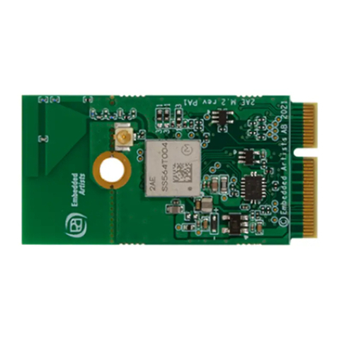
Murata Type1LD Installation and operating instructions

Type1LD Application note HW
Page 1
Introduction
This Application Note targets HW developers.
It provides how to design the Schematic and Layout, and reference RF performance
For Type1LD-EVK manual and quick start guide of WICED refer to
“N1-4629_Type1LD-Quick_Start_Guide_*”
For Module specification refer to “SP-PA1LD-*”
Document Number: E2B-74-0875
Version: B
Release Date: 2019/08/20
Murata Manufacturing Co., Ltd.
Type1LD Application Note
Document No. E2B-74-0875

Type1LD Application note HW
Page 2
Revision History
Revision
Number
Release Date
Comments
2017.Nov.2nd
1st issue
A
2018.Dec.28th
2.1 reference circuit : reviced
B
2019.Aug.20th
2.1 2) 32.768kHz from STM32F412 to CYW43438:Added
comment
2.1 4)External Flash : reviced

Type1LD Application note HW
Page 3
TABLE OF CONTENTS
1Module introduction ................................................................................................................4
1.1 Type1LD Introduction.........................................................................................................4
1.2 Block Diagram.....................................................................................................................4
2Reference Circuit....................................................................................................................5
2.1 Reference Circuit.................................................................................................................5
3HW Design Guideline .............................................................................................................6
3.1 Underneath of module ........................................................................................................6
3.2 External 32.768KHz............................................................................................................7
3.3 Antenna................................................................................................................................7
4. RF Measurement Result.........................................................................................................9
4.1 Tx output power level (at module antenna port) ..............................................................9
4.1.1. WiFi...........................................................................................................................9
4.1.2. Bluetooth...................................................................................................................9
4.2 Rx minimum sensitivity level (at module antenna port) ...............................................10
4.2.1. WiFi.........................................................................................................................10
4.2.2. Bluetooth.................................................................................................................10
5. Current consumption ............................................................................................................11
5.1 WiFi ....................................................................................................................................11
5.1.1. Tx/Rx current consumption.....................................................................................11
5.1.2. Sleep current consumption.....................................................................................11
5.2 Bluetooth............................................................................................................................12
5.2.1. BLE current consumption .......................................................................................12
6. Throughput performance......................................................................................................13

Type1LD Application note HW
Page 4
1 Module introduction
1.1 Type1LD Introduction
WLAN(11b/g/n)+BT/BLE(BT4.1)+MCU(Cortex M4) combo SIP module with Cypress
CYW43438+ST micro STM32F412
Supprted WICED_studio of Cypress
The package type is LGA(SM type)
This module is covered with resin molding and fully shielded with metal
MAC and BD address are embedded in OTP
1.2 Block Diagram
Figure-1 shows module internal block diagram.
Figure-1, Block diagram

Type1LD Application note HW
Page 5
2 Reference Circuit
2.1 Reference Circuit
Figure-2 shows the reference circuit of Type1LD module.
1) 32.768kHz to STM32F412
Table-1 shows 32.768kHz oscillator characteristics for Type1LD.
Symbol
Parameter
Conditions
Min
Typ
Max
Unit
RF
Feedback resistor
-
-
18.4
-
MΩ
IDD
LSE current
consumption
Low-power mode
(default)
-
-
1
uA
High-drive mode
-
-
3
ACCLSE*3
LSE accuracy
-
-200
200
ppm
Cm_crit_max
Maximum critical
crystal gm
Startup, low-power mode
-
-
0.56
Startup, high-drive mode
-
-
1.50
uA/V
tSU(LSE) *2
Startup time
VDD is stabilized
-
2
-
s
*1. Guaranteed by design, not tested in production
*2. tSU(LSE) is the startup time measured from the moment it is enabled (by software) to a
stabilized 32.768kHz oscillation is reached. This value is guaranteed by characterization and not
1
2
3
4
5
A B C D E F G H
1
2
3
4
5
A B C D E F G H
BT_PCM_SYNC
GND
JTDO
JTRST
JTCK
JTDI
USART1_TX
USART1_RX
USART1_CTS
USART1_RTS
nRESET
GND
VDD_IO
PB2/BOOT1
PC4
BOOT0
USART6_TX
USART6_RX
I2C1_SCL
I2C1_SDA
I2C1_SMBA
I2S5_CK
I2S5_WS
I2S5_SD
GND GND
PC5
WL_GPIO_1
WL_GPIO_2
WLRF_GPIO
PB9
PB10
RF_OUT
BT_PCM_OUT
BT_PCM_IN
BT_PCM_CLK
JTMS
SPI2_MOSI
SPI2_MISO
SPI2_SCK
SPI2_NSS
CLK_REQ
4.7uF
0.1uF
4.7uF
0.1uF
VDDA_MCU
GND
0.1uF 4.7uF
4.7uF
0.1uF
VBAT_MCU
0
DEPOP
GND GND
DEPOP
0
DEPOP
GND GND
DEPOP
PI-network attenuator Antenna matching
RF_OUT
VDD_WLAN
PC15/OSC32_OUT
PC14/OSC32_IN
RF line
*0ohm and DEPOP are for initial evaluation.
Please make sure to tune "Antenna matching" and "PI-network attenuator
VBAT_MCU 45
GND
13
GND
12
VDD_IO
34
GND
33
nRESET
32
PB12/SPI2_NSS
31
PB13/SPI2_SCK
30
PB14/SPI2_MISO
29
PB15/SPI2_MOSI
28
PA12/USART1_RTS
27
PA11/USART1_CTS
26
PA10/USART1_RX
25
PA9/USART1_TX
24
GND 46
PA14/JTCK
21
PC1/WAKE
14
WL_GPIO_0_HOST_WAKE
15
LPO_IN
16
PA8/MCO_1
17
PB3/JTDO
18
PB4/JTRST
19
PA13/JTMS
20
PA15/JTDI
22
GND
23
RF_OUT 11
GND 10
BT_PCM_SYNC 9
BT_PCM_OUT 8
BT_PCM_IN 7
BT_PCM_CLK 6
GND 5
VDD_WLAN 4
GND 3
PC14/OSC32_IN 2
PC15/OSC32_OUT 1
GND 65-70
GND 35
PC7/USART6_RX 36
PC6/USART6_TX 37
BOOT0 38
PA7/SPI1_MOSI 39
PA5/SPI1_SCK 40
PA4/SPI1_NSS 41
PA6/SPI1_MISO 42
VSSA/VREF- 43
VDDA_MCU 44
GND
47
GND
48
PC5
49
WL_GPIO_1
50
WL_GPIO_2
51
WLRF_GPIO
52
CLK_REQ
53
PB9
54
PB10
55
GND 64
PB2/BOOT1 63
PB7/I2C1_SDA 62
PB5/I2C1_SMBA 60
PC4 59
PB0/I2S5_CK 58
PB1/I2S5_WS 57
PB8/I2S5_SD 56
PB6/I2C1_SCL 61
LBEE5PA1LD
U1
SPI1_NSS
SPI1_MISO
SPI1_MOSI
SPI1_SCK
PC15/OSC32_OUT
PC14/OSC32_IN
32.768kHz
0ohm
GND GND
X'tal
DO(IO1)
2
/WP(IO2)
3
/CS
1
GND
4
VCC 8
/HOLD(IO3) 7
CLK 6
DI(IO0) 5
W25Q16DVSNIG
SPI1_SCK
SPI1_MOSI
SPI1_MISO
SPI1_NSS
GND
0.1uF
GND
3.3V
Flash
1)
Figure-2, Reference circuit
Table-1, LSE oscillator characteristics (fLSE=32.768kHz)*1
2)
3)
4)

Type1LD Application note HW
Page 6
tested in production. It is measured for a standard crystal resonator and it can vary significantly
with the crystal manufacturer.
*3. +/-200ppm is required for CYW43438.
2) 32.768kHz from STM32F412 to CYW43438
The external 32.768kHz clock is required.
Murata platform folder "MurataType1LD" configures Pin #17 (PA8/MCO_1) as 32.768kHz output.
You can tie Pin #17 with Pin #16 (LPO-IN) to supply sleep clock for CYW43438.
3) Attenuator circuit
Please add attenuator circuit between Type1LD and antenna matching if you use Murata Radio
certification. If your antenna peak gain is higher than Murata application one, please reduce
antenna gain by this pi-type attenuator.
4) External FLASH
The murata platform file setting is set to use External FLASH.
You have to use external FLASH if you want to implement OTA update.
OTA Firmware update implementation by WICED requires external Flash memory.
3 HW Design Guideline
3.1 Underneath of module
1) Please refer to Murata Datashee regarding to Dimensions.
*Murata is preparing DXF file that is module footprint. “Type1LD_bottom_design.dxf”
2) Via design between outside and inside module pad
1)
2)
3)

Type1LD Application note HW
Page 7
Via Hole Φ250um
Via Land Φ500um
3) Module Pin 43 is VSSA/VREF. Pin43 should be separated with Common GND in this area.
3.2 External 32.768KHz
Place ground between X’tal and Power line for isolation.
3.3 Antenna
Antenna line should be 50ohm (*). There should be enough GND via along with Antenna line.
Make sure that pi matching circuit is located right before the wifi antenna on the main board.
(*) How to make 50ohm line?
http://www17.plala.or.jp/i-lab/index_e.htm
Here are the conditions of 50ohm lines of evaluation board. (One of example)
VDD_WLAN
VBAT_MCU
32.768kHz X’tal
Antenna line
Antenna Pad
GND Via
GND Plane

Type1LD Application note HW
Page 8
Epsilon : 4.3
RF trace width(s) : 0.35mm
GND gap(h) : 0.18mm
GND gap(w) : 0.5mm
The line impedance is Z0 = 51.8ohm.

Type1LD Application note HW
Page 9
4. RF Measurement Result
4.1 Tx output power level (at module antenna port)
4.1.1. WiFi
Tx output power setting is defined by Murata nvram file.
4.1.2. Bluetooth
<Condition>
VDD_WLAN=3.3V, VDD_IO=3.3V
WICED_SDK version : 3.7.0
Frequency[MHz]
Output Power [dBm]
DH5
2DH5
3DH5
BLE
2402
8.6
4.5
4.5
7.4
2440
8.9
5.2
5.2
7.7
2480
9.3
5.9
5.9
8.2

Type1LD Application note HW
Page 10
4.2 Rx minimum sensitivity level (at module antenna port)
4.2.1. WiFi
<Condition>
VDD_WLAN=3.3V, VDD_IO=3.3V
WICED_SDK version : 3.7.0
Frequency[MHz]
Rx minimum sensitivity level[dBm]
11b
11g
11n
1Mbps
11Mbps
6Mbps
54Mbps
MCS0
MCS7
2412
-97.1
-90.2
-90.8
-76.6
-91.2
-73.9
2442
-97.3
-89.9
-91.3
-76.5
-91.0
-73.8
2472
-97.2
-89.8
-90.9
-76.4
-90.9
-73.6
4.2.2. Bluetooth
<Condition>
VDD_WLAN=3.3V, VDD_IO=3.3V
WICED_SDK version : 3.7.0
Frequency[MHz]
Rx minimum sensitivity level[dBm]
BR
EDR
BLE
DH5
2DH5
3DH5
2402
-91.5
-94.2
-88.1
-95.5
2440
-91.4
-94.1
-88.0
-95.4
2480
-91.3
-94.0
-87.9
-95.3

Type1LD Application note HW
Page 11
5. Current consumption
5.1 WiFi
5.1.1. Tx/Rx current consumption
<Condition>
VDD_WLAN=3.3V, VDD_IO=3.3V, VDDA_MCU:3.3V, VBAT_MCU=3.3V
WL_REG_ON:ON, BT_REG_ON:OFF
WICED_SDK version : 3.7.0
Rate
setting
power
Tx current[mA]
Rx current[mA]
11b
1Mbps
17
330
55
11Mbps
17
330
11g
6Mbps
17
320
55
54Mbps
13
250
11n
MCS0
17
310
55
MCS7
12
240
5.1.2. Sleep current consumption
<Condition>
VDD_WLAN=3.3V, VDD_IO=3.3V, VDDA_MCU:3.3V, VBAT_MCU=3.3V
WL_REG_ON:ON, BT_REG_ON:OFF
WICED_studio version : 4.1
MCU
Sleep*3
Power save mode
DTIM1*2
DTIM3*2
Stop *1
260uA
2.3mA
1.3mA
*1
The Stop mode achieves the lowest power consumption while retaining the contents of SRAM
and registers. All clocks in the 1.2 V domain are stopped, the PLL, the HSI RC and the HSE
crystal oscillators are disabled. The voltage regulator can also be put either in normal or in
low-power mode. The device can be woken up from the Stop mode by any of the EXTI line (the
EXTI line source can be one of the 16 external lines, the PVD output, the RTC alarm/ wakeup/
tamper/ time stamp events).

Type1LD Application note HW
Page 12
*2
Beacon Interval = 100ms
*3
Device is associated, and then enters Power Save mode(idle between beacons)
5.2 Bluetooth
5.2.1. BLE current consumption
<Condition>
VDD_WLAN=3.3V, VDD_IO=3.3V, VDDA_MCU:3.3V
WL_REG_ON:OFF, BT_REG_ON:ON
WICED_Studio version : 5.0
WICED application : snip.bluetooth.ble_hello_sensor (set ENABLE_APP_POWERSAVE
flag)
BLE Advertise
Unconnectable 1sec[μA]
BLE Connected 1sec[μA]
VDD WLAN
54
54
VDD IO+MCU*
519
533
*MCU Low-power mode : Stop mode

Type1LD Application note HW
Page 13
6. Throughput performance
<Condition>
VDD_WLAN=3.3V, VDD_IO=3.3V, VDDA_MCU:3.3V
WL_REG_ON:ON, BT_REG_ON:OFF
WICED_Studio version : 5.0.1
WICED application : test.console
11n_MCS7
Tx[Mbps]
Rx[Mbps]
TCP
21
25.3
UDP
40.2
36.6
(END)
Other manuals for Type1LD
1
Table of contents
Other Murata Control Unit manuals

Murata
Murata PKGX-14-4010 User manual

Murata
Murata SyChip SN3020 User manual

Murata
Murata 1PS User manual

Murata
Murata ABR User manual

Murata
Murata LBUA5QJ2AB User manual

Murata
Murata Type1XK User manual

Murata
Murata LBAD0ZZ1SE-743 User manual

Murata
Murata LBEE5PK2AE User manual

Murata
Murata SEM2411D User manual

Murata
Murata 1PJ User manual