manuals.online logo
Brands
  1. Home
  2. •
  3. Brands
  4. •
  5. MuxLab
  6. •
  7. Extender
  8. •
  9. MuxLab 500771 User manual

MuxLab 500771 User manual

Specifications
Environment DVI 1.0
Devices Computers and servers with DVI monitor ports.
Transmission Transparent to the user
Bandwidth 300MHz
Signals DVI 1.0 protocol, HDCP 1.4
Connectors
Note: Cables not included.
One (1) DVI receptacle.
One (1) RJ45S for Cat 5e/6 unshielded or shielded twisted pair.
Two (2) 3.5mm jacks for audio insert (on TX)/audio extract (on RX).
Two (2) 3.5mm jacks for mic-out (on TX)/mic-in (on RX).
One (1) 2.1mm locking barrel jack for power
One (1) or Four (4) USB Connector(s) for Host (on TX)/Client (on RX)
Four (4) DIP Switches for device ID addressing.
Maximum Distance
Based on a maximum length
of 6.6ft (2m) of DVI cable
per end.
Cat5e/6: 330ft (100m) up to 1080p @ 60Hz and 1920x1200 @ 60Hz
Note: When installed in an electrically noisy environment, an STP cable must be
used. Also, cross-connection reduces the effective distance depending on the grade
of twisted cable used.
Latency One (1) Frame (16ms) @ 60Hz (typical)
Compression JPEG 2000
Network Bit Rate 300Mbps (typical)
Network Requirement 1000BaseT with PoE
RJ45 Pin Configuration
Reverse Polarity Sensitive.
Use EIA/TIA 568A or 586B
straight-through wiring.
RJ45 Link
Pin 1 (R) Pin 2 (T)
Pin 3 (R) Pin 6 (T)
Pin 4 (R) Pin 5 (T)
Pin 7 (R) Pin 8 (T)
Cable One (1) Cat 5e/6 or better twisted pair cables required
Power Source This device supports PoE (PD), an external power supply is not included. It is
intended to be powered via a PoE (PSE) Ethernet Switch. If required, an optional
power supply (500993) may be purchased separately.
PoE Standard IEEE 802.3af
Power Consumption Transmitter: 2.85Watt Receiver: 2.55Watt
Temperature Operating: 0° to 40°C Storage: -20° to 85°C
Humidity: Up to 95% non-condensing
Dimensions 4.40” x 5.08” x 1.00” (112mm x 129mm x 25mm)
Weight 1.5lbs (0.68kg)
Compliance Regulatory: FCC, CE, RoHS Flammability: 94V0
Warranty 3 years
Order Information 500771 KVM DVI over IP PoE Extender Kit
500771-TX KVM DVI over IP PoE Extender TX
500771-RX KVM DVI over IP PoE Extender RX
Accessories
(These items are sold
separately)
500920 16-Port Rackmount Transceiver Chassis
500917 Wall Mount Transceiver Bracket Kit
500993 Univ. Locking Power Supply 5VDC/2.6A US/UK/EU Blade
KVM DVI over IP PoE Extender Kit
500771
Quick Installation Guide
Overview
The KVM DVI over IP PoE Extender Kit allows DVI & USB equipment to be connected up to
330ft (100m) up to 1080p resolution @ 60Hz and 1920x1200 @ 60Hz via one (1) Cat5e/6
unshielded twisted pair cable in a point-to-point configuration. The Transmitter (500771-TX) and
Receiver (500771-RX) also support PoE (PD) if used with a PoE (PSE) Ethernet Switch. The kit
comes with one (1) Transmitter and one (1) Receiver. Additional Transmitters and Receivers may
be purchased as kits or purchased separately depending on the number of units required.
For multiple point-to-point (including point-to-multipoint) configurations the Ethernet Switch must
have Gigabit ports, Jumbo Frame capability and DHCP Server capability. MuxLab recommends
using the Cisco SG300 Series Managed Switches.
The MuxLab ProDigital Network Controller (500811) is available to simplify the configuration and
utilization of the 500771 and other MuxLab IP based products via an Ethernet web interface.
Applications
Applications include management of multi-server systems supporting DVI displays in IT
departments within corporations, educational institutions, CAD Design, Graphic Design, Media
Servers, and Data Centers.
Installation
1. Identify the connectors on the Transmitter and Receiver as indicated on the product labels, see the
above front and rear product views for further details.
2. Verify that the distance between the DVI Transmitter and Receiver is within MuxLab
specifications (see Specifications table for more details).
3. To install the Transmitter:
3a. Connect the Transmitter DVI port to the Computer DVI port, with a DVI compliant
cable.
3b. Connect the Transmitter USB Port to the Computer USB port, using a compliant Type
A to Type B USB Cable.
3c. If required, connect the computer audio-out and mic-in port to the Transmitter audio-in
and mic-out port, respectively.
3d. If the application is point-to-point, then connect one (1) length of Cat 5e/6 (or higher)
grade UTP cable to the RJ45 LINK connector on the Transmitter. If transmitting over
the network, use an Ethernet Switch between Transmitter and Receiver.
94-000837-B SE-000837-B
4. To install the Receiver:
4a. Connect the Receiver DVI port to the Monitor DVI port with a DVI compliant cable.
4b. Connect the two Receiver USB 1.1 ports to a USB keyboard and mouse.
4c. Connect the two Receiver USB 2.0 ports to other USB devices, such as a printer,
drawing pad, storage device, camera, etc.
4d. If required, connect the Receiver audio-out and mic-in port to an audio/mic system
audio-in and mic-out port, respectively.
4e. If the application is point-to-point, then connect one (1) Cat 5e/6 cable (or higher)
coming from the Transmitter, to the RJ45 LINK connector on the Receiver. If
transmitting over the network, use an Ethernet Switch between Transmitter and
Receiver.
5. If the configuration is a multiple point-to-point (including point-to-multipoint) architecture:
5a. You will need to use an Ethernet Switch with Gigabit ports and DHCP Server support.
In addition Jumbo Frame support is required. Verify that the Ethernet Switch is
configured correctly and that the DHCP Server is enabled and that Jumbo Frame
is enabled. See the operating manual for more information about configuring the
Ethernet Switch.
5b. Connect all Transmitters and Receivers to the Ethernet Switch.
5c. Use the DIP Switches to select a unique Device ID for each Transmitter present on the
network and configure each Receiver Device ID to the corresponding selected
Transmitter.
Note: This step is not necessary if the MuxLab Pro Digital Network Controller
(500811) is used.
6. Powering the Transmitter or Receiver via an external power supply is only necessary where
PoE (PSE) is unavailable. If PoE is unavailable, connect a 5 VDC power supply (500993 -
sold separately) to each Receiver and to an AC power outlet. Next connect each Transmitter
in the same manner. If power is present, the green power LED on each Transmitter and
Receiver will illuminate.
Note: Power ‘ON’ the KVM DVI over IP PoE Extender Kit only after all connections
have been made.
7. Power ‘ON’ the DVI equipment and verify the image quality, sound if applicable, keyboard
and mouse functionality, as well as any additional USB connected devices.
8. There are two basic hot key methods to switch a Receiver among different Transmitters. One
method is via an OSD (On Screen Display) menu, which can be called up by pressing the
hotkey sequence “Scroll Lock” three times in less than 0.5 seconds. This brings up the OSD
menu to select which Transmitter to connect with. The second method is via 16 different
hotkey sequences, with each one providing direct access to a preconfigured Transmitter. This
is available by pressing the CTRL Key with the port number pressed three times within 0.5
seconds. Port numbers follow the switch setting and are from 0 to 9 and q (10), w (11), e
(12), r (13), t (14) and y (15). Hotkeys can be modified from the device web server interface;
to find the IP address of the product use Bonjour Protocol.
9. Please download and reference the 500771 Operation Manual found on the MuxLab website
(under the 500771 webpage) for further instructions on how to operate this device, including
how to configure and use the hotkeys and OSD.
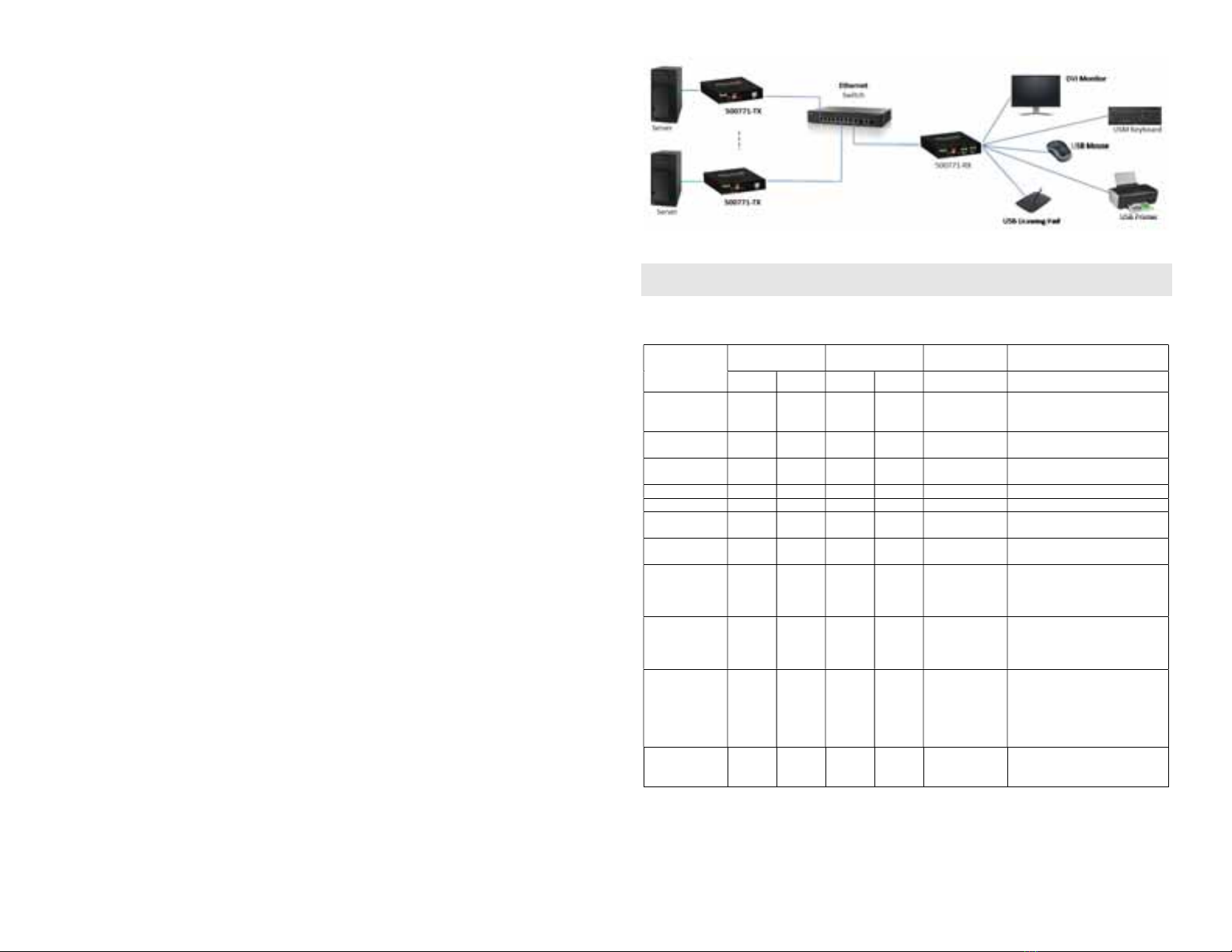
10. The following diagram illustrates a typical point-to-point LAN configuration.
Troubleshooting
The following table describes some of the symptoms, probable causes and possible solutions in regard to
the installation of the KVM DVI over IP PoE Extender Kit:
Symptom
Transmitter LEDs Receiver LEDs Probable
Cause
Possible
Solutions
Power Link Power Link
No Image OFF OFF OFF OFF No power • Check power connections
• Check PoE Ethernet Switch
Setup
No Image BLINK OFF BLINK ON Booting • Wait until booting process is
finished
No Image ON OFF ON OFF No Ethernet Link • Check Ethernet Switch Status
• Check UTP Cables
Info Screen ON OFF ON BLINK UTP Cable • Check the Transmitter UTP cable
Info Screen ON ON ON OFF UTP Cable • Check the Receiver UTP cable.
Info Screen ON BLINK ON BLINK No Data
Connection
• Check if DIP Switch settings
match
Info Screen ON ON ON BLINK Wrong setting on
Receiver
• Check DIP Switch address of the
Receiver
Choppy Video ON ON ON ON Configuration • Check cable length
• Check the DVI Cable Quality
• Check if Jumbo Frame is enabled
on the Ethernet Switch
Image flickers
when powering
up nearby
equipment
ON ON ON ON Interference • Use STP cables
Mouse or
Keyboard not
working or
freezing
ON ON ON ON USB Cable • Check the USB Cable Quality
• Check that the Keyboard and
mouse are connected to the USB
2.0 Port.
• Do not use USB 1.1 ports in this
current release.
USB Speed Slow
ON ON ON ON Wrong Port • Check that any additional USB
devices are connect to the USB
2.0 Port

Other manuals for 500771

4

This manual suits for next models

2

Other MuxLab Extender manuals

MuxLab 500451 User manual

MuxLab

MuxLab 500451 User manual

MuxLab 100504 User manual

MuxLab

MuxLab 100504 User manual

MuxLab 500454 User manual

MuxLab

MuxLab 500454 User manual

MuxLab 500465 User manual

MuxLab

MuxLab 500465 User manual

MuxLab VideoEase 500090 User manual

MuxLab

MuxLab VideoEase 500090 User manual

MuxLab 500754 User manual

MuxLab

MuxLab 500754 User manual

MuxLab 500454-POE User manual

MuxLab

MuxLab 500454-POE User manual

MuxLab 500733 User manual

MuxLab

MuxLab 500733 User manual

MuxLab 500140 User manual

MuxLab

MuxLab 500140 User manual

MuxLab 500771 User manual

MuxLab

MuxLab 500771 User manual

MuxLab 500460 User manual

MuxLab

MuxLab 500460 User manual

MuxLab 500401-WP-UK User manual

MuxLab

MuxLab 500401-WP-UK User manual

MuxLab 500800 User manual

MuxLab

MuxLab 500800 User manual

MuxLab 500730 User manual

MuxLab

MuxLab 500730 User manual

MuxLab 500771 User manual

MuxLab

MuxLab 500771 User manual

MuxLab 500405 User manual

MuxLab

MuxLab 500405 User manual

MuxLab 500759-TX-HLO User manual

MuxLab

MuxLab 500759-TX-HLO User manual

MuxLab 500070 User manual

MuxLab

MuxLab 500070 User manual

MuxLab ProDigital 500485 User manual

MuxLab

MuxLab ProDigital 500485 User manual

MuxLab 500401 User manual

MuxLab

MuxLab 500401 User manual

MuxLab 500752 User manual

MuxLab

MuxLab 500752 User manual

MuxLab 500462 User manual

MuxLab

MuxLab 500462 User manual

MuxLab 500402 User manual

MuxLab

MuxLab 500402 User manual

MuxLab 500753 User manual

MuxLab

MuxLab 500753 User manual

Popular Extender manuals by other brands

Insignia NS-PS5MH4 Quick setup guide

Insignia

Insignia NS-PS5MH4 Quick setup guide

Austin Hughes CyberView CV-K101 user manual

Austin Hughes

Austin Hughes CyberView CV-K101 user manual

Alvarion BreezeACCESS II CX Specifications

Alvarion

Alvarion BreezeACCESS II CX Specifications

Avenview HDM-SHAREPRO-IP user guide

Avenview

Avenview HDM-SHAREPRO-IP user guide

ComNav 20310017 installation instructions

ComNav

ComNav 20310017 installation instructions

ATEN VE1812 user manual

ATEN

ATEN VE1812 user manual

ZyXEL Communications AeroBeam WHD6215 Easy setup guide

ZyXEL Communications

ZyXEL Communications AeroBeam WHD6215 Easy setup guide

Lindy Smart user manual

Lindy

Lindy Smart user manual

Comtrend Corporation WAP-5883 Quick installation guide

Comtrend Corporation

Comtrend Corporation WAP-5883 Quick installation guide

Rose electronics CrystalLink CLK-1U1TP-40M Installation and operation manual

Rose electronics

Rose electronics CrystalLink CLK-1U1TP-40M Installation and operation manual

X10 Big Picture VK25A owner's manual

X10

X10 Big Picture VK25A owner's manual

Halio DR250 installation guide

Halio

Halio DR250 installation guide

Lindy 38403 user manual

Lindy

Lindy 38403 user manual

Network Technologies Incorporated VOPEX-C64K10GB-4HDBT instruction manual

Network Technologies Incorporated

Network Technologies Incorporated VOPEX-C64K10GB-4HDBT instruction manual

CYP CH-506TXPL Operation manual

CYP

CYP CH-506TXPL Operation manual

Luxul PW-FC1 - DUAL ANTENNA user guide

Luxul

Luxul PW-FC1 - DUAL ANTENNA user guide

Samsung Verizon SLS-BU103 quick start guide

Samsung

Samsung Verizon SLS-BU103 quick start guide

FS 4KHDMIRSF quick start guide

FS

FS 4KHDMIRSF quick start guide

manuals.online logo
manuals.online logoBrands
  • About & Mission
  • Contact us
  • Privacy Policy
  • Terms and Conditions

Copyright 2025 Manuals.Online. All Rights Reserved.