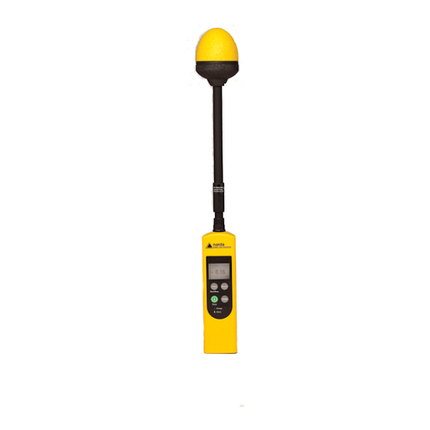
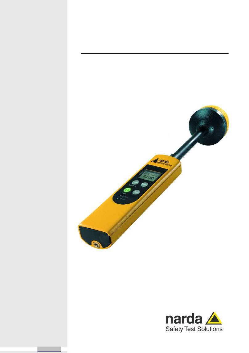
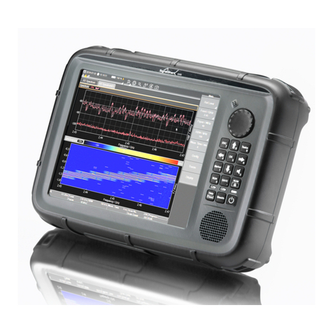
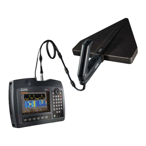
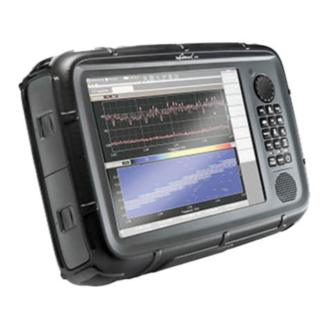
NARDA SRM-3006 User manual

SRM-3006
Selective Radiation Meter
Operating Manual

Narda Safety Test Solutions GmbH
Sandwiesenstraße 7
72793 Pfullingen, Germany
© 2010
Order no.: 3006/98.21
Issue: 03/04.2010, A ...
Previous issues: 02/11.2009, A ...
Subject to change.
Our normal terms of warranty and delivery
apply.
Printed in Germany

Contents
Narda SRM-3006 I
Contents
1 Introduction . . . . . . . . . . . . . . . . . . . . . . . . . . . . . . . . . . . . . . . . . . . . . . 1
1.1 About this device . . . . . . . . . . . . . . . . . . . . . . . . . . . . . . . . . . . 2
1.2 SRM-3006 as a field strength meter . . . . . . . . . . . . . . . . . . . . 4
1.2.1 Basic unit . . . . . . . . . . . . . . . . . . . . . . . . . . . . . . . . . . . . . . . . . 5
1.2.2 Antennas . . . . . . . . . . . . . . . . . . . . . . . . . . . . . . . . . . . . . . . . . 5
1.2.3 Cables . . . . . . . . . . . . . . . . . . . . . . . . . . . . . . . . . . . . . . . . . . . 7
1.3 SRM-3006 as a laboratory device . . . . . . . . . . . . . . . . . . . . . . 8
1.3.1 Basic unit . . . . . . . . . . . . . . . . . . . . . . . . . . . . . . . . . . . . . . . . . 9
1.4 PC software . . . . . . . . . . . . . . . . . . . . . . . . . . . . . . . . . . . . . . . 9
1.5 About this operating manual . . . . . . . . . . . . . . . . . . . . . . . . . 10
1.5.1 User interface language. . . . . . . . . . . . . . . . . . . . . . . . . . . . . 10
1.5.2 Symbols and characters used . . . . . . . . . . . . . . . . . . . . . . . . 10
2 Important Safety Instructions . . . . . . . . . . . . . . . . . . . . . . . . . . . . . . 13
2.1 Using this operating manual . . . . . . . . . . . . . . . . . . . . . . . . . 14
2.2 Before connecting up. . . . . . . . . . . . . . . . . . . . . . . . . . . . . . . 14
2.3 Proper use . . . . . . . . . . . . . . . . . . . . . . . . . . . . . . . . . . . . . . . 14
2.4 Improper use . . . . . . . . . . . . . . . . . . . . . . . . . . . . . . . . . . . . . 15
2.5 General hazards . . . . . . . . . . . . . . . . . . . . . . . . . . . . . . . . . . 15
2.6 Dangers due to electromagnetic fields . . . . . . . . . . . . . . . . . 16
2.7 AC adapter / charger . . . . . . . . . . . . . . . . . . . . . . . . . . . . . . . 18
2.8 Rechargeable batteries . . . . . . . . . . . . . . . . . . . . . . . . . . . . . 19
2.8.1 Storage . . . . . . . . . . . . . . . . . . . . . . . . . . . . . . . . . . . . . . . . . 19
2.8.2 Handling . . . . . . . . . . . . . . . . . . . . . . . . . . . . . . . . . . . . . . . . 20
2.8.3 Fire hazards. . . . . . . . . . . . . . . . . . . . . . . . . . . . . . . . . . . . . . 20
2.8.4 Chemical hazards . . . . . . . . . . . . . . . . . . . . . . . . . . . . . . . . . 21
2.8.5 Charging and discharging . . . . . . . . . . . . . . . . . . . . . . . . . . . 21
2.8.6 Disposal . . . . . . . . . . . . . . . . . . . . . . . . . . . . . . . . . . . . . . . . . 22
2.9 Faults and unusual stresses . . . . . . . . . . . . . . . . . . . . . . . . . 22
2.10 Proper disposal . . . . . . . . . . . . . . . . . . . . . . . . . . . . . . . . . . . 22

Contents
II SRM-3006 Narda
3 Connecting Up and Starting to Use the Device. . . . . . . . . . . . . . . . 23
3.1 Unpacking the device . . . . . . . . . . . . . . . . . . . . . . . . . . . . . . 24
3.1.1 Packaging . . . . . . . . . . . . . . . . . . . . . . . . . . . . . . . . . . . . . . . 24
3.1.2 Package contents . . . . . . . . . . . . . . . . . . . . . . . . . . . . . . . . . 24
3.1.3 Checking the device for shipping damage . . . . . . . . . . . . . . 24
3.1.4 Recovery after shipping and storage . . . . . . . . . . . . . . . . . . 24
3.2 Device overview . . . . . . . . . . . . . . . . . . . . . . . . . . . . . . . . . . 25
3.2.1 Display and control panels . . . . . . . . . . . . . . . . . . . . . . . . . . 25
3.2.2 Device side panel with antenna / cable connectors . . . . . . . 26
3.2.3 Device side panel with battery compartment . . . . . . . . . . . . 26
3.2.4 Device side panel with external connectors . . . . . . . . . . . . . 27
3.3 Power supply . . . . . . . . . . . . . . . . . . . . . . . . . . . . . . . . . . . . 27
3.3.1 Operation from battery pack . . . . . . . . . . . . . . . . . . . . . . . . . 28
3.3.2 Handling battery packs . . . . . . . . . . . . . . . . . . . . . . . . . . . . . 29
3.3.3 Operation from AC adapter / charger . . . . . . . . . . . . . . . . . . 30
3.4 Fitting the antenna . . . . . . . . . . . . . . . . . . . . . . . . . . . . . . . . 30
3.4.1 Fitting a Narda antenna directly on the Basic Unit . . . . . . . . 30
3.4.2 Connecting a Narda antenna
to the Basic Unit using a Narda cable. . . . . . . . . . . . . . . . . . 31
3.4.3 Using commercially-available cables and antennas . . . . . . . 33
3.4.4 Fitting a Narda antenna on a tripod . . . . . . . . . . . . . . . . . . . 33
4 Operation and Basic Settings . . . . . . . . . . . . . . . . . . . . . . . . . . . . . . 39
4.1 Controls . . . . . . . . . . . . . . . . . . . . . . . . . . . . . . . . . . . . . . . . 40
4.1.1 Rotary control and keys . . . . . . . . . . . . . . . . . . . . . . . . . . . . 40
4.1.2 Softkeys . . . . . . . . . . . . . . . . . . . . . . . . . . . . . . . . . . . . . . . . 41
4.2 Switching the device on and off . . . . . . . . . . . . . . . . . . . . . . 41
4.3 LCD screen elements . . . . . . . . . . . . . . . . . . . . . . . . . . . . . . 42
4.3.1 The upper status bar. . . . . . . . . . . . . . . . . . . . . . . . . . . . . . . 43
4.3.2 The lower status bar . . . . . . . . . . . . . . . . . . . . . . . . . . . . . . . 44
4.3.3 The navigator bar . . . . . . . . . . . . . . . . . . . . . . . . . . . . . . . . . 45
4.3.4 Activating / deactivating status and info bars . . . . . . . . . . . . 45

Contents
Narda SRM-3006 III
4.4 Fundamental operating steps . . . . . . . . . . . . . . . . . . . . . . . . 46
4.4.1 Navigating in the menus . . . . . . . . . . . . . . . . . . . . . . . . . . . . 46
4.4.2 Selecting entries from a list . . . . . . . . . . . . . . . . . . . . . . . . . . 47
4.4.3 Changing numerical values . . . . . . . . . . . . . . . . . . . . . . . . . . 49
4.4.4 Entering text. . . . . . . . . . . . . . . . . . . . . . . . . . . . . . . . . . . . . . 50
4.4.5 Softkeys with toggle function . . . . . . . . . . . . . . . . . . . . . . . . . 51
4.4.6 Creating a screenshot . . . . . . . . . . . . . . . . . . . . . . . . . . . . . . 51
5 The Main Menu . . . . . . . . . . . . . . . . . . . . . . . . . . . . . . . . . . . . . . . . . . 53
5.1 Overview of functions and operating modes . . . . . . . . . . . . . 54
5.2 Display and editing device and component settings . . . . . . . 55
5.2.1 Changing the language, date, and time. . . . . . . . . . . . . . . . . 56
5.2.2 Editing device-specific settings . . . . . . . . . . . . . . . . . . . . . . . 57
5.2.3 Displaying device information . . . . . . . . . . . . . . . . . . . . . . . . 58
5.2.4 Displaying GPS information. . . . . . . . . . . . . . . . . . . . . . . . . . 59
5.2.5 Resetting all device settings . . . . . . . . . . . . . . . . . . . . . . . . . 59
5.2.6 Performing device diagnosis . . . . . . . . . . . . . . . . . . . . . . . . . 60
5.2.7 Displaying and selecting the available antennas . . . . . . . . . . 61
5.2.8 Displaying and selecting the available cables . . . . . . . . . . . . 61
5.2.9 Displaying and selecting the safety standards. . . . . . . . . . . . 62
5.2.10 Displaying and creating service tables . . . . . . . . . . . . . . . . . 62
5.3 The memory menu . . . . . . . . . . . . . . . . . . . . . . . . . . . . . . . . 64
5.4 Using measurement routines. . . . . . . . . . . . . . . . . . . . . . . . . 65
5.4.1 Displaying measurement routines . . . . . . . . . . . . . . . . . . . . . 65
5.4.2 Starting a measurement routine . . . . . . . . . . . . . . . . . . . . . . 66
5.5 Saving and loading setups. . . . . . . . . . . . . . . . . . . . . . . . . . . 66
5.5.1 Saving settings as a setup. . . . . . . . . . . . . . . . . . . . . . . . . . . 66
5.5.2 Loading settings from a setup . . . . . . . . . . . . . . . . . . . . . . . . 66
5.5.3 Editing the setup list. . . . . . . . . . . . . . . . . . . . . . . . . . . . . . . . 67
5.5.4 Deleting setups . . . . . . . . . . . . . . . . . . . . . . . . . . . . . . . . . . . 67
5.5.5 Changing the switch on behavior. . . . . . . . . . . . . . . . . . . . . . 68

Contents
IV SRM-3006 Narda
6 Functions Common to More Than One Operating Mode . . . . . . . . 69
6.1 Overview of functions
common to more than one operating mode . . . . . . . . . . . . . 70
6.2 Setting the resolution bandwidth (RBW). . . . . . . . . . . . . . . . 71
6.2.1 Setting the video bandwidth (VBW) . . . . . . . . . . . . . . . . . . . 71
6.3 Setting the measurement range (Meas. Range). . . . . . . . . . 72
6.3.1 Manual measurement range selection . . . . . . . . . . . . . . . . . 73
6.3.2 Automatic measurement range search (MR Search) . . . . . . 74
6.3.3 Measurement input overload . . . . . . . . . . . . . . . . . . . . . . . . 74
6.4 Selecting the result type (Result Type) . . . . . . . . . . . . . . . . . 75
6.4.1 Average formation (Result type: Average) . . . . . . . . . . . . . . 76
6.4.2 Reset measurement values . . . . . . . . . . . . . . . . . . . . . . . . . 77
6.5 The Marker function . . . . . . . . . . . . . . . . . . . . . . . . . . . . . . . 77
6.5.1 Using the markers separately . . . . . . . . . . . . . . . . . . . . . . . . 78
6.5.2 Using both markers to determine a difference . . . . . . . . . . . 80
6.5.3 Displaying the marker data on the measurement screen . . . 82
6.5.4 Zooming to marker . . . . . . . . . . . . . . . . . . . . . . . . . . . . . . . . 83
6.6 Selecting an axis mode. . . . . . . . . . . . . . . . . . . . . . . . . . . . . 84
6.6.1 Measurement using a three axis antenna. . . . . . . . . . . . . . . 85
6.6.2 Measurement using a single axis antenna . . . . . . . . . . . . . . 86
6.7 Adjusting the Y axis . . . . . . . . . . . . . . . . . . . . . . . . . . . . . . . 88
6.8 Changing the displayed units . . . . . . . . . . . . . . . . . . . . . . . . 89
6.9 Noise suppression (Noise Thresh.) . . . . . . . . . . . . . . . . . . . 90
6.10 Measuring spatial average values (Spatial AVG) . . . . . . . . . 91
6.11 Changing operating mode
and keeping the same parameters . . . . . . . . . . . . . . . . . . . . 91
6.12 Useful shortcuts . . . . . . . . . . . . . . . . . . . . . . . . . . . . . . . . . . 92
6.12.1 Selecting a service table or a service . . . . . . . . . . . . . . . . . . 92
6.12.2 Saving a setup . . . . . . . . . . . . . . . . . . . . . . . . . . . . . . . . . . . 92

Contents
Narda SRM-3006 V
7 Safety Evaluation Mode . . . . . . . . . . . . . . . . . . . . . . . . . . . . . . . . . . . 93
7.1 About Safety Evaluation mode. . . . . . . . . . . . . . . . . . . . . . . . 94
7.2 Basic settings. . . . . . . . . . . . . . . . . . . . . . . . . . . . . . . . . . . . . 96
7.2.1 Selecting the display mode . . . . . . . . . . . . . . . . . . . . . . . . . . 96
7.2.2 Activating the beeper . . . . . . . . . . . . . . . . . . . . . . . . . . . . . . . 96
7.2.3 Showing and hiding services . . . . . . . . . . . . . . . . . . . . . . . . . 97
7.2.4 Setting the resolution bandwidth (RBW) . . . . . . . . . . . . . . . . 97
7.2.5 Setting the measurement range (Meas. Range) . . . . . . . . . . 98
7.2.6 Selecting the result type (Result Type) . . . . . . . . . . . . . . . . . 98
7.2.7 Measuring in the gaps between defined services (Others) . . 99
7.3 Using the Table view . . . . . . . . . . . . . . . . . . . . . . . . . . . . . . . 99
7.3.1 Changing the table displayed. . . . . . . . . . . . . . . . . . . . . . . . 100
7.3.2 Percentage display . . . . . . . . . . . . . . . . . . . . . . . . . . . . . . . 101
7.4 Using the Bar Graph view . . . . . . . . . . . . . . . . . . . . . . . . . . 103
7.4.1 Adjusting the Y axis (Y-Scale) . . . . . . . . . . . . . . . . . . . . . . . 103
7.4.2 Changing the displayed units (Unit) . . . . . . . . . . . . . . . . . . . 103
7.4.3 The Marker function. . . . . . . . . . . . . . . . . . . . . . . . . . . . . . . 104
7.5 Selecting an axis mode . . . . . . . . . . . . . . . . . . . . . . . . . . . . 104
8 Spectrum Analysis Mode . . . . . . . . . . . . . . . . . . . . . . . . . . . . . . . . . 105
8.1 About Spectrum Analysis mode . . . . . . . . . . . . . . . . . . . . . 106
8.2 Basic settings. . . . . . . . . . . . . . . . . . . . . . . . . . . . . . . . . . . . 106
8.2.1 Changing the frequency range . . . . . . . . . . . . . . . . . . . . . . 107
8.2.2 Setting the resolution bandwidth (RBW) . . . . . . . . . . . . . . . 108
8.2.3 Setting the video bandwidth (VBW) . . . . . . . . . . . . . . . . . . . 108
8.2.4 Changing the displayed units (Unit) . . . . . . . . . . . . . . . . . . . 108
8.2.5 Adjusting the Y axis (Y-Scale) . . . . . . . . . . . . . . . . . . . . . . . 109
8.3 Evaluating the measurement data (Evaluation). . . . . . . . . . 109
8.3.1 Displaying the peak values (Peak Table) . . . . . . . . . . . . . . . 110
8.3.2 Integrating measured values (Integration) . . . . . . . . . . . . . . 112
8.4 The Marker function (Marker) . . . . . . . . . . . . . . . . . . . . . . . 114
8.5 The Zoom function (Zoom) . . . . . . . . . . . . . . . . . . . . . . . . . 114

Contents
VI SRM-3006 Narda
9 Level Recorder Mode. . . . . . . . . . . . . . . . . . . . . . . . . . . . . . . . . . . . 117
9.1 About Level Recorder mode . . . . . . . . . . . . . . . . . . . . . . . . 118
9.2 Display overview . . . . . . . . . . . . . . . . . . . . . . . . . . . . . . . . . 119
9.2.1 Activating the beeper . . . . . . . . . . . . . . . . . . . . . . . . . . . . . 120
9.3 Basic settings . . . . . . . . . . . . . . . . . . . . . . . . . . . . . . . . . . . 120
9.3.1 Selecting the center frequency (Fcent). . . . . . . . . . . . . . . . 120
9.3.2 Setting the resolution bandwidth (RBW). . . . . . . . . . . . . . . 120
9.3.3 Setting the video bandwidth (VBW) . . . . . . . . . . . . . . . . . . 120
9.3.4 Setting the measurement range (Meas. Range). . . . . . . . . 121
9.3.5 Selecting the result type (Result Type) . . . . . . . . . . . . . . . . 121
9.4 Selecting an axis mode (Axis) . . . . . . . . . . . . . . . . . . . . . . 122
9.5 Using noise suppression (Noise Thresh.). . . . . . . . . . . . . . 122
10 Scope Mode . . . . . . . . . . . . . . . . . . . . . . . . . . . . . . . . . . . . . . . . . . . 123
10.1 About Scope mode . . . . . . . . . . . . . . . . . . . . . . . . . . . . . . . 124
10.2 Display overview . . . . . . . . . . . . . . . . . . . . . . . . . . . . . . . . . 124
10.3 Setting the measurement parameters . . . . . . . . . . . . . . . . 125
10.3.1 Limits of values that can be set . . . . . . . . . . . . . . . . . . . . . 126
10.3.2 Example 1: GSM. . . . . . . . . . . . . . . . . . . . . . . . . . . . . . . . . 127
10.3.3 Example 2: DECT telephone . . . . . . . . . . . . . . . . . . . . . . . 127
10.3.4 Example 3: WLAN . . . . . . . . . . . . . . . . . . . . . . . . . . . . . . . 128
10.3.5 Example 4: Remote automobile key (ISM band) . . . . . . . . 130
10.4 Using the trigger function . . . . . . . . . . . . . . . . . . . . . . . . . . 131
10.5 Evaluating the measurement results (Evaluation) . . . . . . . 133
11 UMTS Mode. . . . . . . . . . . . . . . . . . . . . . . . . . . . . . . . . . . . . . . . . . . . 135
11.1 About UMTS mode . . . . . . . . . . . . . . . . . . . . . . . . . . . . . . . 136
11.2 Display overview . . . . . . . . . . . . . . . . . . . . . . . . . . . . . . . . . 137
11.3 Explanation of measurement result display . . . . . . . . . . . . 138
11.3.1 Individual results . . . . . . . . . . . . . . . . . . . . . . . . . . . . . . . . . 138
11.3.2 Total result (Total) . . . . . . . . . . . . . . . . . . . . . . . . . . . . . . . . 138

Contents
Narda SRM-3006 VII
11.3.3 Partial results for certain radio cells
(scrambling codes) . . . . . . . . . . . . . . . . . . . . . . . . . . . . . . . 139
11.3.4 Analog measurement result (Analog) . . . . . . . . . . . . . . . . . 139
11.4 Basic settings. . . . . . . . . . . . . . . . . . . . . . . . . . . . . . . . . . . . 139
11.4.1 Setting the center frequency (Fcent) . . . . . . . . . . . . . . . . . . 140
11.4.2 Showing and hiding services . . . . . . . . . . . . . . . . . . . . . . . . 140
11.4.3 Resetting the table (Reset Table) . . . . . . . . . . . . . . . . . . . . 140
11.4.4 Setting the measurement range (Meas. Range) . . . . . . . . . 141
11.4.5 Selecting the result type (Result Type) . . . . . . . . . . . . . . . . 141
11.4.6 Using an extrapolation factor . . . . . . . . . . . . . . . . . . . . . . . . 141
11.5 Performing a coverage measurement . . . . . . . . . . . . . . . . . 142
11.6 Using noise suppression (Noise Thresh.) . . . . . . . . . . . . . . 142
12 Spatial Averaging . . . . . . . . . . . . . . . . . . . . . . . . . . . . . . . . . . . . . . . 143
12.1 About the Spatial Averaging function. . . . . . . . . . . . . . . . . . 144
12.2 Description of averaging functions. . . . . . . . . . . . . . . . . . . . 145
12.2.1 Continuous. . . . . . . . . . . . . . . . . . . . . . . . . . . . . . . . . . . . . . 146
12.2.2 Discrete . . . . . . . . . . . . . . . . . . . . . . . . . . . . . . . . . . . . . . . . 147
12.2.3 Discrete Axis . . . . . . . . . . . . . . . . . . . . . . . . . . . . . . . . . . . . 148
12.3 Spatial Averaging – Continuous. . . . . . . . . . . . . . . . . . . . . . 149
12.4 Spatial Averaging – Discrete . . . . . . . . . . . . . . . . . . . . . . . . 151
12.5 Spatial Averaging – Discrete Axis . . . . . . . . . . . . . . . . . . . . 153
13 Measurement Data Memory . . . . . . . . . . . . . . . . . . . . . . . . . . . . . . . 157
13.1 About the Memory menu . . . . . . . . . . . . . . . . . . . . . . . . . . . 158
13.2 Viewing data sets. . . . . . . . . . . . . . . . . . . . . . . . . . . . . . . . . 159
13.3 Viewing screenshots . . . . . . . . . . . . . . . . . . . . . . . . . . . . . . 160
13.4 Saving measured values automatically . . . . . . . . . . . . . . . . 161
13.4.1 Conditional Storing of measured values . . . . . . . . . . . . . . . 161
13.4.2 Time Controlled Storing of measured values. . . . . . . . . . . . 163
13.4.3 Changing the comment modes . . . . . . . . . . . . . . . . . . . . . . 165

Contents
VIII SRM-3006 Narda
14 Maintenance and Repairs . . . . . . . . . . . . . . . . . . . . . . . . . . . . . . . . 167
14.1 Changing the battery pack . . . . . . . . . . . . . . . . . . . . . . . . . 168
14.2 Cleaning . . . . . . . . . . . . . . . . . . . . . . . . . . . . . . . . . . . . . . . 168
14.3 AC adapter / charger. . . . . . . . . . . . . . . . . . . . . . . . . . . . . . 169
15 PC Software . . . . . . . . . . . . . . . . . . . . . . . . . . . . . . . . . . . . . . . . . . . 171
15.1 PC software versions and functions . . . . . . . . . . . . . . . . . . 172
15.2 Connecting to the PC . . . . . . . . . . . . . . . . . . . . . . . . . . . . . 172
15.3 Working with the PC software. . . . . . . . . . . . . . . . . . . . . . . 173
16 Remote Control . . . . . . . . . . . . . . . . . . . . . . . . . . . . . . . . . . . . . . . . 175
16.1 About remote control . . . . . . . . . . . . . . . . . . . . . . . . . . . . . 176
16.2 Connecting to the PC . . . . . . . . . . . . . . . . . . . . . . . . . . . . . 176
16.3 Activating / deactivating remote control . . . . . . . . . . . . . . . 177
16.3.1 Solving problems . . . . . . . . . . . . . . . . . . . . . . . . . . . . . . . . 177
16.4 Syntax rules for remote control commands . . . . . . . . . . . . 177
16.4.1 Commands to the SRM-3006 . . . . . . . . . . . . . . . . . . . . . . . 177
16.4.2 SRM-3006 responses . . . . . . . . . . . . . . . . . . . . . . . . . . . . . 178
16.4.3 Example of a command sequence . . . . . . . . . . . . . . . . . . . 179
17 Specifications. . . . . . . . . . . . . . . . . . . . . . . . . . . . . . . . . . . . . . . . . . 181
17.1 SRM-3006. . . . . . . . . . . . . . . . . . . . . . . . . . . . . . . . . . . . . . 182
17.1.1 RF features . . . . . . . . . . . . . . . . . . . . . . . . . . . . . . . . . . . . . 182
17.1.2 Modes . . . . . . . . . . . . . . . . . . . . . . . . . . . . . . . . . . . . . . . . . 184
17.1.3 Measurement functions . . . . . . . . . . . . . . . . . . . . . . . . . . . 188
17.1.4 General specifications . . . . . . . . . . . . . . . . . . . . . . . . . . . . 190
17.2 Three axis E-field antenna 3501/03 . . . . . . . . . . . . . . . . . . 192
17.2.1 Characteristics . . . . . . . . . . . . . . . . . . . . . . . . . . . . . . . . . . 192
17.2.2 Uncertainty . . . . . . . . . . . . . . . . . . . . . . . . . . . . . . . . . . . . . 193
17.2.3 General specifications . . . . . . . . . . . . . . . . . . . . . . . . . . . . 193
17.3 Three axis E-field antenna 3502/01 . . . . . . . . . . . . . . . . . . 195
17.3.1 Characteristics . . . . . . . . . . . . . . . . . . . . . . . . . . . . . . . . . . 195

Contents
Narda SRM-3006 IX
17.3.2 Uncertainty . . . . . . . . . . . . . . . . . . . . . . . . . . . . . . . . . . . . . 196
17.3.3 General specifications . . . . . . . . . . . . . . . . . . . . . . . . . . . . . 196
17.4 Three axis H-field antenna 3581/02. . . . . . . . . . . . . . . . . . . 197
17.4.1 Characteristics. . . . . . . . . . . . . . . . . . . . . . . . . . . . . . . . . . . 197
17.4.2 Uncertainty . . . . . . . . . . . . . . . . . . . . . . . . . . . . . . . . . . . . . 198
17.4.3 General specifications . . . . . . . . . . . . . . . . . . . . . . . . . . . . . 198
17.5 Single axis E-field antenna 3531/01 . . . . . . . . . . . . . . . . . . 199
17.5.1 Characteristics. . . . . . . . . . . . . . . . . . . . . . . . . . . . . . . . . . . 199
17.5.2 Uncertainty . . . . . . . . . . . . . . . . . . . . . . . . . . . . . . . . . . . . . 199
17.5.3 General specifications . . . . . . . . . . . . . . . . . . . . . . . . . . . . . 200
17.6 Single axis E-field antenna 3531/04 . . . . . . . . . . . . . . . . . . 201
17.6.1 Characteristics. . . . . . . . . . . . . . . . . . . . . . . . . . . . . . . . . . . 201
17.6.2 Uncertainty . . . . . . . . . . . . . . . . . . . . . . . . . . . . . . . . . . . . . 201
17.6.3 General specifications . . . . . . . . . . . . . . . . . . . . . . . . . . . . . 201
17.7 Single axis H-field antenna 3551/02 . . . . . . . . . . . . . . . . . . 203
17.7.1 Characteristics. . . . . . . . . . . . . . . . . . . . . . . . . . . . . . . . . . . 203
17.7.2 Uncertainty . . . . . . . . . . . . . . . . . . . . . . . . . . . . . . . . . . . . . 203
17.7.3 General specifications . . . . . . . . . . . . . . . . . . . . . . . . . . . . . 203
17.8 Declaration of Conformity . . . . . . . . . . . . . . . . . . . . . . . . . . 205
18 Annex A . . . . . . . . . . . . . . . . . . . . . . . . . . . . . . . . . . . . . . . . . . . . . . . 207
18.1 Pendulum method . . . . . . . . . . . . . . . . . . . . . . . . . . . . . . . . 208
18.2 Matrix method (precision measurement) . . . . . . . . . . . . . . . 210
19 Ordering Information . . . . . . . . . . . . . . . . . . . . . . . . . . . . . . . . . . . . 213
19.1 SRM-3006 sets . . . . . . . . . . . . . . . . . . . . . . . . . . . . . . . . . . 214
19.2 Antennas . . . . . . . . . . . . . . . . . . . . . . . . . . . . . . . . . . . . . . . 215
19.3 Options . . . . . . . . . . . . . . . . . . . . . . . . . . . . . . . . . . . . . . . . 215
19.4 Accessories . . . . . . . . . . . . . . . . . . . . . . . . . . . . . . . . . . . . . 216
20 Glossary. . . . . . . . . . . . . . . . . . . . . . . . . . . . . . . . . . . . . . . . . . . . . . . 219
Index. . . . . . . . . . . . . . . . . . . . . . . . . . . . . . . . . . . . . . . . . . . . . . . . . . 223

Contents
X SRM-3006 Narda

Narda SRM-3006 1
1Introduction
This chapter contains basic information on measuring electromagnetic
fields, on using the SRM-3006, and on how this manual is laid out.
1.1 About this device (page 2)
1.2 SRM-3006 as a field strength meter (page 4)
1.3 SRM-3006 as a laboratory device (page 8)
1.4 PC software (page 9)
1.5 About this operating manual (page 10)

1 Introduction
2 SRM-3006 Narda
1.1 About this device
The SRM-3006 (Selective Radiation Meter) is a handy-sized frequency-
selective measuring system for safety analysis and environmental
measurements in high frequency electromagnetic fields in the frequency
range from 9 kHz to 6 GHz. Because signals with frequencies of this
magnitude are very difficult to sample digitally, the SRM-3006 uses a
combination of analog and digital signal processing. It is ideal for measuring
absolute and limit values of high-frequency electromagnetic fields such as
those due to broadcast radio (AM, FM), TV (analog, DVB-T), BOS (Tetra),
mobile telecommunications (GSM, UMTS), radar, and wireless
communications (WiMax, WLAN).
In unknown field environments such as those around so-called shared sites,
where several providers of mobile telephone services share a common
antenna site, the SRM-3006 displays the total field level as well as the
contributions made by the individual services, either as absolute values or
as a percentage of the permitted limit level. Each service can be resolved
down to its individual channels and the contribution made by each channel
to the overall field emission measured using the SRM-3006. In the same
way, the value can be integrated over the frequency band of the service and
the total value displayed, again as an absolute value or in terms of the
relevant limit value. The SRM-3006 naturally also includes all the typical
functions of a spectrum analyzer and as such can be universally applied. An
added bonus is the high measurement speed at small resolution bandwidths
(RBW).
The device combines a very wide and varied range of functions within an
extremely lightweight and handy design. This makes it possible to use the
device particularly under the kind of conditions where good mobility and
ruggedness are required.
The complete SRM-3006 measuring system comprises the Basic Unit
SRM-3006 and the three axis antenna. Narda Safety Test Solutions also
supplies other antennas for the Basic unit, including single axis antennas,
covering various applications and frequency ranges. All Narda antennas
can be mounted directly on the Basic Unit or connected to it using a special
RF cable.
Other commercially available antennas can be connected to the SRM-3006
by cables; these cables can also be of types other than those supplied by
Narda.

1 Introduction
Narda SRM-3006 3
Figure 1: SRM-3006 in on-site use

1 Introduction
4 SRM-3006 Narda
1.2 SRM-3006 as a field strength meter
The SRM-3006 is a device for measuring electromagnetic fields in the
frequency range 9 kHz to 6 GHz. The main measurement task here is the
determination of the field strength.
Several operating modes can be selected. Each operating mode is
designed to deliver in-situ immediate, informative results that do not require
any further processing or evaluation.
In the simplest case, the complete measuring equipment for determining the
field strength consists of the Basic Unit with an antenna mounted directly on
it.
Depending on the selected measurement method, it may be useful or even
necessary not to mount the antenna directly on the Basic Unit but to place it
some distance away and use a cable to connect it.
A 1.5 m long cable is included in all SRM-3006 field strength measuring
system sets including antenna that are offered by Narda Safety Test
Solutions. A 5 m long cable is available for special applications (see
Ordering Information on page 213).
The antenna needs to be exactly positioned and undisturbed for precision
measurements. An optionally available tripod with a suitable antenna holder
can be added to the measuring equipment for this purpose.
Regardless of the package described, cables and antennas not made by
Narda can also be connected to the Basic Unit in order to perform the
desired measurements (see Using commercially-available cables and
antennas on page 33).

1 Introduction
Narda SRM-3006 5
1.2.1 Basic unit
The SRM-3006 is a field meter that has been specially designed for use
outdoors and in difficult to reach or uncomfortable measurement locations.
The functions of the device have therefore been tailored to ensure ease of
handling in practical situations.
Some of the most outstanding features are:
• Handy sized and light in weight despite a wide range of functions
• Ergonomically shaped non-slip grips ensure that the device can be held
securely and that all controls can be easily reached during the
measurement
• Additional fitting for attaching a wrist strap on the left hand side of the
device
• Large, clear LCD with backlight is easy to read under various lighting
conditions
• Foil keypad ensures reliable operation under poor conditions or when
wearing gloves
• Fast, hassle-free rechargeable battery replacement for longer on-site
operating times
1.2.2 Antennas
The standard contents of a SRM-3006 set usually include a three axis
antenna. This three axis antenna allows quick and simple isotropic
measurements with automatic determination of the three spatial
components of the field to be measured. It too has been designed for use
outdoors and in hard to reach measurement locations (see Ordering
Information on page 213).
Narda Safety Test Solutions also supplies other single axis and three axis
antennas for electric and magnetic field measurements which cover further
applications and lower frequency ranges.
Every Narda antenna is equipped with a control cable in addition to the RF
conductor. This is connected to the Basic Unit by a multi-pin connector, and
transfers the antenna parameters (type, serial number, calibration date, list
of antenna factors) to the Basic Unit so that the SRM-3006 can recognize
and use this data.

1 Introduction
6 SRM-3006 Narda
Other commercially-available antennas can also be connected to the Basic
Unit. The table below indicates the types of antenna that can be used to
determine field strength exposure levels.
Note: Existing antennas with a frequency range extending down to
100 kHz can be modified for use at frequencies down to 9 kHz. This
modification is free of charge when performed in conjunction with a
calibration (but modification from 75 MHz to 27 MHz will be charged
for). You can get further information from one of our Sales Partners
in your locality or from our homepage www.narda-sts.de under
Service.
Table 1: Antenna types
Type Field
type
Frequency range
(typical values)
Remarks
Three Axis E-field 420 MHz – 6 GHz For rapid, non-directional
measurements in the frequency
range of the latest generation of
wireless technologies and mobile
phones.
Three Axis E-field 27 MHz – 3 GHz Universal solution for rapid, non-
directional measurements.
Single Axis E-field 27 MHz – 3 GHz For precision measurements in the
frequency range most used by
communications services.
Single Axis E-field 9 kHz – 300 MHz For precision measurements of
electric fields around radio/TV
transmitters and industrial
equipment.
Three Axis H-field 9 kHz – 250 MHz For rapid, non-directional near
field measurements on magnetic
fields around radio/TV transmitters
and industrial equipment.
Single Axis H-field 9 kHz – 300 MHz For precision near field
measurements on magnetic fields
around radio/TV transmitters and
industrial equipment.

1 Introduction
Narda SRM-3006 7
1.2.3 Cables
Narda Safety Test Solutions supplies two cables for the connection between
the antenna and the Basic Unit. Both cables are suitable for the frequency
range between 9 kHz and 6 GHz. The cables are 1.5 m and 5 m long and
contain ferrite to reduce the effect of the external field on the measurement
results. The cables include a control cable along with the RF conductor. This
control cable is connected to the Basic Unit by a multi-pin connector, and
transfers the antenna parameters (type, serial number, calibration date, list
of attenuation factors) to the Basic Unit so that the SRM-3006 can recognize
and use this data. This cable also allows the SRM-3006 to control
successive measurement of each of the three axes to determine the
isotropic result, or selection of a single axis to determine directional
information.
Commercially-available cables can also be used for the connection between
the Basic Unit and the antenna. However, three axis antennas cannot be
controlled using such cables.
Note: Existing cables with a frequency range from 100 kHz to 3 GHz can
be modified for use at frequencies between 9 kHz and 6 GHz. This
modification is free of charge when performed in conjunction with a
calibration. You can get further information from one of our Sales
Partners in your locality or from our homepage www.narda-sts.de
under Service.

1 Introduction
8 SRM-3006 Narda
1.3 SRM-3006 as a laboratory device
Since the SRM-3006 Basic Unit has all the typical features of a spectrum
analyzer, it can also be used in this capacity under laboratory conditions.
Figure 2: SRM-3006 in laboratory use
The SRM-3006 can be integrated into the required measurement
environment directly via the N connector or by means of a cable. The test
generator signals can be fed directly into the basic unit via the N connector.
The SRM-3006 set includes a 1.5 m long cable. A 5 m long cable can be
ordered as an optional accessory (see Ordering Information on page 213).
Other manuals for SRM-3006
3
Table of contents
Other NARDA Measuring Instrument manuals

NARDA
NARDA SRM-3006 Operating manual

NARDA
NARDA L3HARRIS SMARTS II User manual

NARDA
NARDA NBM-550 User manual

NARDA
NARDA EHP-50-G User manual

NARDA
NARDA AMB-8059 User manual

NARDA
NARDA nbm-520 User manual

NARDA
NARDA EFA-200 User manual

NARDA
NARDA SRM-3006 User manual

NARDA
NARDA IDA User manual

NARDA
NARDA SignalShark User manual

NARDA
NARDA PMM CA0010 User manual

NARDA
NARDA EHP-50F User manual

NARDA
NARDA 8718B User manual

NARDA
NARDA NRA Series Instruction Manual

NARDA
NARDA FieldMan User manual

NARDA
NARDA PMM 6600 User manual

NARDA
NARDA NIM-511 User manual

NARDA
NARDA SRM-3000 User manual

NARDA
NARDA HP-01 User manual

NARDA
NARDA ESM-10 RadMan Mobile User manual