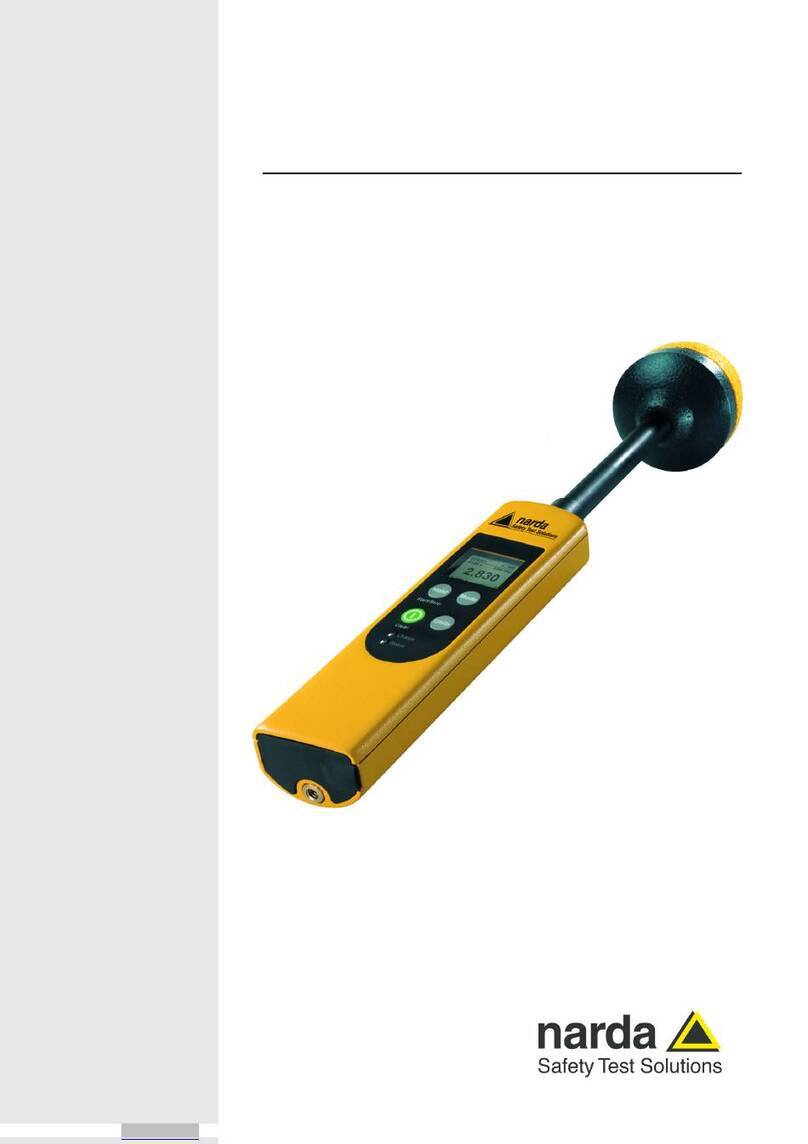
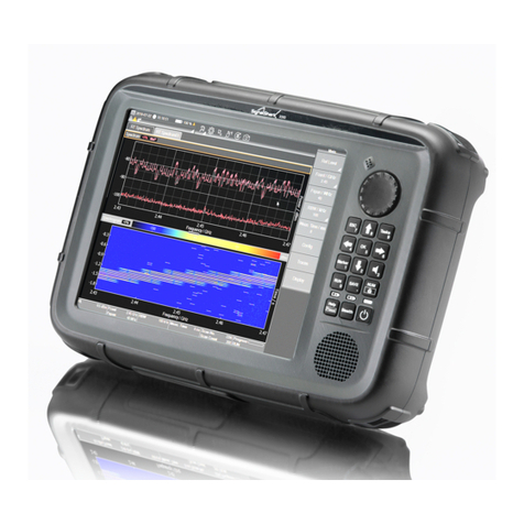
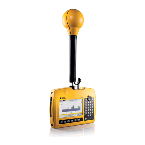
NARDA SRM-3006 User manual

SRM: WHEN SAFETY COUNTS
SRM-3006: SELECTIVE RADIATION METER
FOR ELECTROMAGNETIC FIELDS
UP TO 6 GHz

2
SAFETY?
Radio, TV, mobile phones, wireless services: Electromag-
netic fields are the medium wherever such forms of
communication are used. These fields affect everything
around them including the people that are moving
within them. Complete coverage would otherwise be
impossible.
National and international authorities have fixed limit
values for such fields to prevent harmful effects. The
field strengths allowed in the occupational environment
are usually higher than those for the general public,
because people who routinely work in electromagnetic
fields are trained, aware of the potential dangers, and
know what to do or have specific instructions which, for
example, limit exposure time to the field.
AM FM DVB-T DAB

3
CHECK!
Legislators have laid the responsibility for ensuring safety
upon the operators of transmitting equipment and the
relevant authorities. These, in turn, can take advantage
of the measurement services offered by organizations
and independent providers. There is really only one way
to make sure everything is safe:
TETRA GSM UMTS CDMA WIMAX LTE
Photo reproduced by kind permission of
ORS – Österreichische Rundfunksender GmbH & Co KG
Austrian Broadcasting Services, www.ors.at

4
CHECK? HOW?
SRM: WHEN SAFETY COUNTS
Wideband measuring equipment gives blanket coverage
of large frequency ranges, which could range from
the broadcast band to the mobile phone band and
beyond, for example. When fitted with special probes,
such equipment can deliver results that are expressed
automatically in terms of the applicable permitted limit
values. These devices are usually easy to operate.
Selective devices such as spectrum analyzers break the
fields down into their individual frequency components,
allowing detailed analysis. They are more complex to
operate and some specialist knowledge is needed to
evaluate results.
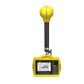
The Selective Radiation Meter SRM-3006 from Narda
Safety Test Solutions combines the analysis features of
a spectrum analyzer with the simple application of a
wideband measuring set. It was developed specifically
to address safety concerns in electromagnetic fields. In
contrast to a “converted” spectrum analyzer, it provides
users with application-oriented operating modes for
measuring separate transmission channels and services
such as analog or digital broadcasts (TV, DVB-T, DAB),
mobile phones (GSM, UMTS, LTE) or wireless (WLAN,
WiMAX). Results are displayed as individual values in
tables and as an overall total value, expressed in units of
field strength, power density, or simply as a percentage
of the permitted limit value. You don’t need to be an
expert in spectrum analysis to use the SRM.

5
The Selective Radiation Meter and its
measuring antennas are matched.
Any antenna and any instrument in the
range can be combined to form a
handy unit. Plug and Play.
The results can be shown in physical units, e.g. electric field strength in
V/m, magnetic field strength in A/m, and power density in W/cm2,
or directly as a percentage of the limit values, for example those
specified by ICNIRP. Important: The SRM can also subsequently
convert results to percentages, physical units or logarithmic
quantities.
V/m A/m W/cm2%

6
DEPENDABLE?
SRM: WHEN SAFETY COUNTS
Legally airtight, trustworthy results depend on many
factors: The measuring equipment must be calibrated.
The measurement must comply with standards, and it
must be made professionally and correctly.
The SRM from Narda Safety Test Solutions is calibrated
– traceable to national and international standards. It
fulfills all the requirements of current human safety
standards. And it makes correct, professional measure-
ments easy, such as time-averaged measurements over
the standard six-minute period or spatial averaging over
several measurement points. When using the isotropic
measuring antennas for the SRM, you don’t need to
worry about the direction of the field either; the instru-
ment doesn’t miss a thing. And you can set up and save
measurement routines in advance, ensuring reproduc-
ible results and eliminating incorrect settings.
The SRM can create measurement reports on-site, so
there’s no possibility of transmission errors creeping
in. The instrument includes the underlying standard in
the result, records the date, time and GPS coordinates,
and also saves written or voice comments, which can
describe e.g. the ambient conditions or any events that
occur during the measurement. All this means that you
always get dependable results.
GPS TIME DATE VOICE

7
Impossible to falsify: Screenshot of a ‘Safety Evaluation’ result.
The calibration certificate
records the traceability
of the calibration of the
instrument and antenna
to recognized standards
– with accreditation if
requested.

8
SRM – WHAT FOR?
SRM: FOR EVERYTHING
Electromagnetic fields always consist of an electrical and
a magnetic field component. Limit values are therefore
specified for both the electric as well as the magnetic
field strength.
The electric and magnetic field strengths at a distance
from the source are in a fixed relationship, so it is suffi-
cient to measure just one of the two components. This
relationship does not apply close to the source, so both
components must be determined separately.
The wavelength of the radiation determines the location
of the near-field and the far-field. The near-field of a
long wave transmitter extends for several kilometers.
The near-field for mobile phone antennas ends within
the space of about one meter.
Narda Safety Test Solutions has developed a thoroughly
researched range of measuring antennas. They make
the SRM into a universal measuring set for electric and
magnetic fields – from long wave up to the latest gene-
ration of mobile phone frequencies.
The isotropic (three-axis)
measuring antenna for electric
fields (E-fields) up to 3 GHz
is the all-round solution for
trouble-free measurements
covering VSW to UMTS.
Inside the isotropic electric
field measuring antenna,
showing three dipoles
arranged at mutual
right angles.

9
ISOTROP – SINGLE AXIS
ALL-PURPOSE MEASURING ANTENNAS
Quick and reliable because they are non-directional:
The isotropic antennas detect the field strengths in
three mutually perpendicular directions, and the SRM
automatically calculates the resulting field strength.
Nevertheless, isotropic measurements are also possible
using the single-axis antennas if you use a tripod and
the antenna holder, which allows you to make suc-
cessive measurements in three mutually perpendicular
positions. The SRM supports this procedure by saving
the result for each of the three positions and then calcu-
lating the resulting field strength – without a PC.
All antennas and antenna cables are interchangeable
without affecting accuracy: The calibration data for
each item is saved in the antenna or cable itself and is
read out and applied automatically by the SRM Basic
Unit. At the same time, the SRM blocks the frequency
ranges for which the antenna has not been calibrated.
This avoids incorrect measurements.
For rapid, non-directional
measurements involving
latest generation wireless
technologies: Three-axis
(isotropic) E-field antenna
for frequencies from
420 MHz to 6 GHz
For rapid, non-directional
measurements, e.g.
covering mobile phone
frequencies: Three-axis
(isotropic) E-field antenna
for frequencies from
27 MHz to 3 GHz
The measuring antennas can be connected to the SRM Basic
Unit directly or via a cable. An auxiliary control cable allows
the Basic Unit to read out the measuring antenna and antenna
cable data automatically.
For precision measure-
ments in the mobile
phone frequency range:
Single-axis E-field
antenna for frequencies
from
27 MHz to 3 GHz
For precision electric
field measurements on
radio / TV transmitters
and industrial equipment:
Single-axis E-field antenna
for frequencies from von
9 kHz to 300 MHz
For precision magnetic field
measurements in the nearfield of
radio / TV transmitters and industrial
equipment: Single-axis H-field
antenna for frequencies fromn
9 kHz to 300 MHz
E-FELD
H-FELD
For rapid, non-directional
magnetic field measure-
ments in the near-field of
radio / TV transmitters and
industrial equipment: Three-
axis H-field antenna for
frequencies from
9 kHz to 250 MHz
The single-axis antennas can be mounted on a tripod and
adjusted to produce isotropic results by making measurements
in three mutually perpendicular positions. Hand-held, they are
also ideal for locating maximum values within a room using the
so-called pendulum method.

10
WHO? WHAT?
SRM FOR DETAILS
Broadcasting, mobile telephony, industrial equipment:
What proportion of the overall field is from which
source? The answer is of interest to the relevant authori-
ties and safety representatives as well as to the opera-
tors themselves. There is often a need to know what
field strength is emanating from which equipment,
which channel or which radio cell. This determines who
must reduce output power in the event that the limit
values are exceeded, for example. On the other hand,
the overall field strength is more important when it
comes to human safety and environmental protection.
The Selective Radiation Meter SRM is perfect for
such investigations, thanks to its application-oriented
operating modes. For example: ‘Safety Evaluation’
with automatic evaluation of individual services such
as analog TV, digital radio (DVB-T, DAB), mobiles (GSM,
UMTS, LTE), and wireless (WLAN, WiMAX), as well as a
summary of the results in the form of an overall value.
Or ‘Level Recorder’ mode, which can even record pulsed
radar signals as numerical values. Or ‘Scope’ mode,
which displays the variation of the field over time.
Even the resolution bandwidths are tailored to the
applications. Using these settings, the SRM can select
out a single narrow GSM channel or capture an entire
broad DVB-T channel.
SPECTRUM ANALYSIS SAFETY EVALUATION UMTS DEMODULATION LTE MODE
Overview with ‘Safety Evaluation’: The
services to be checked are recorded in
editable tables. There’s no complicated
evaluation needed in ‘Safety Evaluation’
mode: The numerical result shows the
individual contributions of the services
as well as the overall level in terms of
the permitted limit value.
Classical spectrum analysis: Result
evaluation using markers and delta
markers. The integration function can
be used to determine the channel
power level, for example. Special
feature: Service identification by
means of pre-recorded service tables.
LEVEL RECORDER SCOPE

11
SPECTRUM ANALYSIS SAFETY EVALUATION UMTS DEMODULATION LTE MODE
Which channels are occupied? The bar
graph display in ‘Safety Evaluation’
mode shows maximum, average, and
minimum values simultaneously, so you
can clearly see what’s going on.
UMTS P-CPICH Demodulation: The SRM
automatically identifies every received
UMTS cell by means of its scrambling
code and measures the field strength
or power density of the associated
pilot channel (P-CPICH) at the same
time. The SRM also shows the sum of
all P-CPICH levels as an overall value
(Total). The analog measured value for
the frequency channel is also shown for
comparison. You can also set a factor
that the SRM can use to extrapolate
the field strength that would result
if all channels were fully loaded.
View pulsed signals directly in ‘Scope’
mode: The time domain display can be
set to cover a period of 24 hours or can
be more finely resolved, even down to
the microsecond level.
Measure pulsed signals easily in ‘Level
Recorder’ mode: The SRM complements
the numerical display of maximum
and minimum values with a bar graph
‘thermometer’ display: A marker remains
on the maximum level in each case.

12
KEEP CHECKING
SRM FOR LONG-TERM MONITORING
It doesn’t take long to measure the actual field exposure
level. But how does the level change over a period of
seconds, minutes, hours, or even days?
The SRM-3006 records individual radio channels in real
time with microsecond resolution in ‘Scope’ mode; this
capability is needed in order to capture radar impulses.
On the other hand, the instrument can also be used for
long-term measurements, such as a ‘Safety Evaluation’.
The flow of data doesn’t have to become a flood,
though. The start and sequence of measurements can
be timer controlled or triggered when a threshold is
crossed. The SRM then summarizes the data sets in a
clear display.
Particularly convenient: The SRM determines the instan-
taneous, average, maximum, and minimum values at
the same time.
The SRM can operate independently for about three
hours on fully charged batteries. The batteries can easily
be replaced on-site, so there’s no need to hunt for the
nearest power outlet.
Long term monitoring in the workplace: Even the WLAN connection
to a laptop and the in-house wireless telephones contribute to the
field exposure level. The SRM can be operated for hours or days
on end using an AC adapter.

13
Practical, on-site battery exchange: With a spare
set of batteries, you can run the equipment for
a whole day without needing AC line power.
‘Safety Evaluation’ in a residential area:
Is it really only the mobile phone base
stations that are the source of the field?
ACT AVG MAX MIN MAX AVG MIN AVG

14
EVERYDAY CHECKS
There is a different field situation at each different
measurement location. However, the measurements
themselves are repeated. Narda Safety Test Solutions has
equipped the SRM-3006 with programmable measure-
ment routines for this reason. The SRM runs through
specific setups in succession and performs the necessary
tasks. This saves time, avoids incorrect measurements,
and means that the results from different locations are
comparable and reproducible.
The SRM can do a lot of things automatically if you want
it to, such as setting a suitable measurement range and
selecting the appropriate resolution bandwidth. You
can also easily perform measurement steps manually,
such as switching from the FM radio range to the DVB-T
range or from GSM-900 to GSM-1800.
Prepare
Measure
Evaluate

15
ROUTINE WITH SRM
Switching between operating modes also includes some
clever features. For example, if you determine the center
frequency of a UMTS frequency channel using spectrum
analysis, the SRM will continue measuring at exactly
that frequency when you switch to ‘UMTS P-CPICH
Demodulation’, ‘Scope’, or ‘Level Recorder’ mode.
Meaningful measurement involves a process, which
begins with configuring the instrument and ends with
the evaluation, documentation, and management of
the measured data. The SRM-3006 TS PC software lets
you do all this easily.
You can also combine instrument setups into measure-
ment routines and upload them to the SRM using the PC
software. Conversely, you can download the results from
the SRM, evaluate, record, and discuss them without any
time-consuming further processing on a PC.

16
INSIGHT
A single spectrum captured using the SRM contains
thousands of measurement points. During the course
of a normal working day, the SRM may store many such
spectra along with other results. Which data is import-
ant, what information is relevant for assessing safety?
You don’t need to be a spectrum analysis specialist to
use the SRM. Nevertheless, experts can set all the par-
ameters for spectrum analysis individually and evaluate
the details manually. For example, you can zoom in on
individual lines in the spectrum, compare spectral com-
ponents using the delta marker, or read off the maxima
and minima at a specific frequency. You can also select
a video bandwidth to smooth the trace, just as with a
laboratory spectrum analyzer. The original resolution is
still retained in the background.
Selective measurement in the time domain is unique:
Pulsed signals can be displayed directly in ‘Scope’ mode
– with time intervals ranging from hours right down to
microseconds. In ‘Level Recorder’ mode, the SRM-3006
displays the instantaneous peak and RMS values as well
Detailed evaluation of a ‘Spectrum
Analysis’ in the 1800 MHz mobile
phone range (GSM-1800): Using
the Delta marker, spectral com-
ponents can be compared or the
maxima and minima at a specific
frequency can be read out.
‘Safety Evaluation’ with bar graph
display: Professional users can
immediately see the difference
between traffic channels (TCH)
and control channels (BCCH)
when the maximum, average, and
minimum values are displayed
simultaneously.
Pulsed fields in ‘Scope’ mode:
As with an oscilloscope, you can
measure impulse lengths and
period durations. And you can
also set triggers: Measure once
when the threshold is exceeded,
or each time the threshold is
exceeded – or by timer control.

17
OVERVIEW
as the maximum peak and RMS values that occurred
during the measurement. With a resolution bandwidth
extending up to 32 MHz, the SRM-3006 is also fully
equipped to handle the latest generation of mobile
communications systems.
Expert users don’t need to put up with inconvenience,
either. The SRM automatically generates a list, even
from the most detailed spectrum. This ‘Peak Table’ gives
access to important details.
Keep it simple: Evaluation of a
‘Spectrum Analysis’ using the ‘Peak
Table’. The list of the highest field
strengths and their corresponding
frequencies, service names and even
the names of the service providers if
these have been recorded in service
tables is particularly convenient. Items
in the table can be sorted according
to various criteria.
‘Safety Evaluation’ in the UMTS range:
The individual channels with their
channel numbers are shown next to each
other in the bar graph display, just like
a textbook. The “T” bar on the extreme
right shows the total power density. The
“O” bar shows the contributions from
the frequency gaps (others) between the
services.

18
ON-SITE OR LAB?
ON-SITE AND LAB
Handy enough for on-site work but with high-end
specifications suitable for laboratory use – the SRM
offers both.
The Basic Unit has a footprint which is about the same
size as this brochure. Together with the measuring
antenna, it forms a unit that can easily be carried up
any tower. The combination is ergonomically designed,
mechanically robust, and splash proof. The casing is
electrically resistant to field strengths of up to 200 V/m.
This means that you can still measure the field strength
in areas where most other instruments have long
ceased to function. Many of its features show their real
worth in difficult environments: the voice recorder
for spoken comments, the rough textured rear panel
ensuring you have a good grip, and the large area key-
pad that can still be operated even if you are wearing
gloves.
Nevertheless, the specifications of the SRM-3006 are
such that it can double as a laboratory instrument:
An unusually high maximum bandwidth of 32 MHz, a
signal to noise ratio that is excellent for a hand-held
device, and the standard N connector that can be used
to connect cables and antennas from other manu-
facturers.
Everything on hand: Measuring workplace safety using the SRM Basic Unit and measuring antenna.
Photo reproduced by kind permission of ORS –
Österreichische Rundfunksender GmbH & Co KG
Austrian Broadcasting Services, www.ors.at

19
Ergonomics for the lab: The SRM can be set at a tilt
so it is easy to operate and read.
The advantage of a specialized
device: If required, the SRM
evaluates directly according to
safety standards. Shown here:
ICNIRP occupational and general
public limit value curves.
1 10 100 1k 10k 100k 1M 10M 100M 1G 10G 100G
10
100
1k
10k
100k
0,1 f [Hz]
[V/m]
occupational
OCC., ICNIRP 1998
OCC., ICNIRP 2010
Gen. Pub., ICNIRP 1998
Gen. Pub., ICNIRP 2010
general public

20
VERSIONS AND FUNCTIONS
The Selective Radiation Meter SRM-3006 is available
packaged in various sets of equipment; for example:
Basic Unit with isotropic (three-axis) E-field measuring
antenna up to 6 GHz – or – Basic Unit with isotropic
(three-axis) E-field measuring antennas up to 3 GHz and
6 GHz. Each set also includes the SRM-3006 Tools PC
software, USB cable, AC adapter / charger, wrist strap
and carry strap. The equipment is fitted in a choice of
either a soft case or a rigid shell case.
All these components as well as other equipment can be
supplied as accessories.
Please refer to the latest data sheet at our website
www.narda-sts.com for detailed specifications.
For analyzing the field exposure level
in detail, as a graph or table, with
display of individual values and
calculation of the exposure due
to entire frequency ranges
For a rapid overview of
the field exposure level
as a graph, a table,
or a total value
For a rapid overview of
time-variable fields, with
numerical display of
peak and RMS
values
For detailed real time recording
and evaluation of
time-variable fields
Pilot channel (P-CPICH)
demodulation and extrapolation
to the maximum possible
field exposure level
Time or event controlled recording
User-defined configuration
Importation of calibration data
Measurement routines, setups
Spatial averaging
Voice recorder
GPS
SAFETY EVALUATION
SPECTRUM ANALYSIS
LEVEL RECORDER
SCOPE (OPTION)
UMTS (OPTION)
ALLGEMEINE FUNKTIONEN
Power level measurement of Primary (PSS)
and Secondary Sync Signal (SSS),
Reference Signal (RS)
LTE (OPTION)
Other manuals for SRM-3006
3
Table of contents
Other NARDA Measuring Instrument manuals

NARDA
NARDA 8718B User manual

NARDA
NARDA SRM-3006 Operating manual

NARDA
NARDA PMM CA0010 User manual

NARDA
NARDA 8061 User manual

NARDA
NARDA FieldMan User manual

NARDA
NARDA IDA User manual

NARDA
NARDA RadMan 2LT User manual

NARDA
NARDA PMM 6600 User manual

NARDA
NARDA L3HARRIS SMARTS II User manual

NARDA
NARDA SignalShark User manual

NARDA
NARDA AMS-8061 User manual

NARDA
NARDA AMB-8059 User manual

NARDA
NARDA NIM-511 User manual

NARDA
NARDA nbm-520 User manual

NARDA
NARDA ESM-10 RadMan Mobile User manual

NARDA
NARDA EFA-200 User manual

NARDA
NARDA EHP-50F User manual

NARDA
NARDA NBM-550 User manual

NARDA
NARDA nbm-520 User manual

NARDA
NARDA 8718 User manual