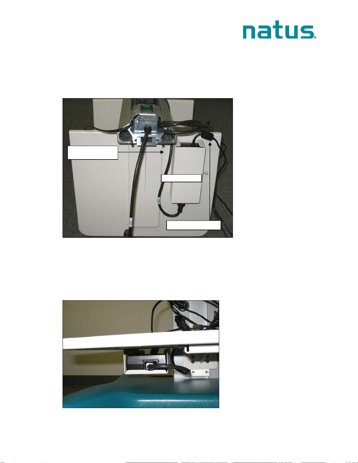
manuals.online logo
Brands
  1. Home
  2. •
  3. Brands
  4. •
  5. natus
  6. •
  7. Medical Equipment
  8. •
  9. natus ALGO 5 Guide

natus ALGO 5 Guide

ALGO® 5 Newborn Hearing Screener Service Manual
P/N 000995 Rev.A 1
ALGO 5 Installation and Assembly Instructions
1. Preparation
Examine the shipping containers carefully upon receipt. If any of the boxex are damaged or
the packing materials show signs of stress, notify the carrier and keep the shipping materials
for the carrier’s inspection.
The ALGO 5 includes these items packaged and shipped separately in 4 boxes::
•Cart base with Isolation Transformer
•Cart column (with cable guide protective covers included but not installed)
•Panel PC with Panel PC power supply
•Accessories box: keyboard, DSP Box, Preamp 5, ATA 5 cable, Sample Pack, label
printer, and accessories pack: Equipment Check Kit, USB Cable, two PCA 5 cables,
CD, power cord, and documentation package
•Optional items packaged separately: Barcode scanner, LAN Isolator, and page
printer.
Note: Save shipping boxes and packing foam in the event that the screening module
must be returned to the manufacturer.
Required Tools
•T-handle allen wrench, 3/16” (supplied, in Cart Base packaging)
•90 degree allen wrench, 1/8” and 5/32” (supplied, in Cart Column packaging)
•7/16” standard wrench or adjustable crescent wrench (not supplied)
•Phillips screwdriver (not supplied)
Hardware Supplied
•Socket head screws (#1/4-20 x 1 1/4”) with lock washers & flat washers (4, in Cart
Base packaging)
•KEP nuts (#1/4-20) – (2, in Cart Base packaging)
•Socket head cap screws (#10-32 x 1/2” SHCS) - (4, in Cart Column packaging)
•Pan head screws (#10-32 x 3/8” PHMS) - (4, packaged separately, taped to DSP
bracket on Cart Column)
•Post cap plate – (1, in Cart Column packaging)
•Button head socket cap screws (#1/4-20 x 3/8” BHSCS) – (4, packaged with post cap
plate)
2 ALGO® 5 Newborn Hearing Screener Service Manual
P/N 000995 Rev.A
Below is a view of the assembled ALGO 5:
FIGURE 1: ALGO 5— front view
DSP Box
Drawer for Disposables
Cart Column with Integrated
Cable Management
Isolation Transformer
Keyboard
Label Printer
Shelf Space
Page Printer
(optional)
Panel PC
ALGO® 5 Newborn Hearing Screener Service Manual
P/N 000995 Rev.A 3
Cart Column with
Integrated Cable
Management –
Rear View
FIGURE 2: ALGO 5 — rear view
DSP Box –
Rear View
Preamp 5 Holder
Cable
Management
Prongs for ATA 5
& PCA 5 Cables
Barcode
Scanner
(optional
Power Supply
for DSP Box
mounted in the
column
Main Switch
Power Supply
for Label Printer
mounted in the
column
Optional Power
Supply for Inkjet
Page Printer
4 ALGO® 5 Newborn Hearing Screener Service Manual
P/N 000995 Rev.A
Figure 3: ALGO 5 Accessories
2. Mount the ALGO 5 Cart Column onto the Base
•Open shipping carton.
•Lift the cart base from its packaging. Set the cart base on the floor. Note the
opening in the cart base that allows the column to be mounted to the base (FIGURE
4). Identify the hardware used to secure the column to the base: two KEP nuts with
integrated lock washers, four ¼-20 x 1 ¼” socket-head cap screws with associated
washers (FIGURE 5).
ATA 5
PCA 5
Preamp 5
DSP
Equipment
Check Kit
ALGO® 5 Newborn Hearing Screener Service Manual
P/N 000995 Rev.A 5
FIGURE 4: Mount Column onto the Base
FIGURE 5: Hardware used to secure the Column to the base
•Place protective cardboard or plastic on the floor, and carefully lay the cart column on the
floor next to the base, with the flat side of the column (shelf side) facing down and the
main switch facing up (see FIGURE 6 for orientation):
6 ALGO® 5 Newborn Hearing Screener Service Manual
P/N 000995 Rev.A
FIGURE 6: Cart from the back
•With the shelves facing down, align the base opening with the column. Carefully
route the six cables hanging from the bottom of the cart column one at a time through
the opening in the cart base. The opening allows the column to be fitted in only one
way (see FIGURE 4). Slide the cart base onto the column’s two alignment threaded
studs (FIGURE 7). Note: packaging of cart may include foam and caps for the studs
which will need to be removed prior to assembly.
NOTE: The sixth cable is for the optional page printer. It is included but not shown in
FIGURE 4 or FIGURE 7.
FIGURE 7: Detail Column alignment threaded studs
Alignment
Studs
Plastic Nut
ALGO® 5 Newborn Hearing Screener Service Manual
P/N 000995 Rev.A 7
•Hand-tighten the plastic nut at the base of the main switch if it is loose (FIGURE 7).
Insert nuts with integrated lock washers onto each of the two threaded studs with the
lock washer towards the column, and then tighten the nuts using the 7/16” wrench.
Tighten until snug, and then tighten at least an additional half turn so that lock washer
bites into base metal. Insert the four socket head cap screws with washers and
tighten using the T-handle 3/16” allen wrench (FIGURE 8 and FIGURE 9). Tighten
until snug, then tighten at least another half turn.
FIGURE 8: View from bottom 1
8 ALGO® 5 Newborn Hearing Screener Service Manual
P/N 000995 Rev.A
•Route the Cables
oInstall the inlet power cord from the Power Inlet to the Isolation Transformer
(FIGURE 9 and FIGURE 10).
FIGURE 9: Inlet Power Cord Location
FIGURE 10: Route the cables
oInsert remaining five cables in such a way that (1) the thinnest cable is inserted in
the uppermost outlet and (2) for the remaining four cables, the shortest cable
lengths are inserted into the nearest plugs (FIGURE 10).
Inlet Power
Cord
Inlet Power
Cord
ALGO® 5 Newborn Hearing Screener Service Manual
P/N 000995 Rev.A 9
3. Install the Panel PC power supply
Note: The Cart Column has two pre-installed power supplies, one for the DSP Box and
one for the label printer.
•Unpack the power supply for the Panel PC (included in the Panel PC box).
•Locate the small box just under the lowest shelf (FIGURE 11).
FIGURE 11: Lowest shelf as from seen underneath
•Loosen the attached thumb screw. Slide the power supply into the box from the front
so that the end that connects to the cable from the transformer faces toward the front
of the cart assembly. Route the cable that connects to the Panel PC through the
lowest opening in the cart column to the back of the column (FIGURE 12), up along
the back of the column. Do not route the output cord through the highest opening
until the Panel PC is in place.
FIGURE 12: Route Panel PC power supply cable
Cable to Panel PC
Pre-installed
Power Cable
Thumb Screw
10 ALGO® 5 Newborn Hearing Screener Service Manual
P/N 000995 Rev.A
4. Install the Panel PC
•Stand the assembled cart column upright on the cart base. Unpack the Panel PC
and lay it face down on a flat surface. CAUTION: To avoid scratching the screen
surface, DO NOT remove the protective film until the ALGO 5 is completely
assembled.
•On the recessed flat surface at the back of the Panel PC, there are four screw holes
used to mount the PC to the PC mount (FIGURE 14). Using the 90-degree 5/32”
allen wrench provided (FIGURE 13), place socket head cap screws (#10-32 x
1/2“ SHCS) into the top two inner holes and tighten until the screws stop, then loosen
a full five rotations (1/8” space between screw and plastic).
FIGURE 13: 90 degree 5/32” allen wrench provided
FIGURE 14: Back of Panel PC
ALGO® 5 Newborn Hearing Screener Service Manual
P/N 000995 Rev.A 11
•Be certain that the tilt tension screws that hold the PC mount to the cart column (the
top two – FIGURE 16) are tightened securely to hold the pivot in place. Hang the
Panel PC on the PC mount by sliding the two screws inserted in the previous step
onto the slotted screw holes (FIGURE 15).
FIGURE 15: Back view showing 2 screws
•Tilt the Panel PC forward to facilitate access to the top screws, and tighten the two
screws.
FIGURE 16: Side view showing 4 screws
•Tilt the panel PC up, and insert two addition screws into the bottom 2 holes on the
PC holder, and tighten with a 90-degree allen wrench (FIGURE 16).
Tilt Tension
Screws
12 ALGO® 5 Newborn Hearing Screener Service Manual
P/N 000995 Rev.A
5. Install the Keyboard
•Unpack the keyboard and set aside. Pull the top drawer all the way out from beneath
the writing surface to reveal the front of the cart column.
•The DSP mounting bracket must be temporarily moved to provide access for routing
the printer cable to the Panel PC (see FIGURE 17). Using the 1/8” allen wrench,
unscrew the two lower set screws that hold the mounting bracket to the cart column,
slide the bracket up by about 3”, and tighten the screws to hold the bracket in place.
FIGURE 17: Access for routing the printer cable
•Place the keyboard on the top drawer. Route the keyboard cable out through the
hole behind the tray that holds the keyboard and up through the cable routing guide
on the cart column (FIGURE 18). Plug the keyboard cable into the Panel PC to any
of the available USB ports on the bottom (FIGURE 20).
FIGURE 18: Routing the keyboard cable
Slide
Up
ALGO® 5 Newborn Hearing Screener Service Manual
P/N 000995 Rev.A 13
NOTE: To facilitate routing the keyboard USB cable, the sliding keyboard tray may
optionally be removed. To remove the tray, pull it out fully. Press the tabs on
both sides simultaneously while pulling on the tray (FIGURE 19). The rails that
hold the tray are greased, so clean-up may be required.
FIGURE 19: Removing the keyboard tray
14 ALGO® 5 Newborn Hearing Screener Service Manual
P/N 000995 Rev.A
FIGURE 20: Panel PC Interface
•Return the keyboard tray and the top drawer to their original positions. Loosen the
screws that secure the DSP mounting bracket, slide the bracket back down to its
original position, and tighten BOTH screws to ensure ground contact (FIGURE 17).
6. Install the DSP Box
•Unpack the DSP Box. Remove the four screws provided in the bag attached to the
DSP mounting bracket. Position the DSP Box so that the power receptacle (black
cable in FIGURE 21) faces the left side of the cart as viewed from the front. Install
the four screws to secure the DSP Box to the mounting bracket.
Power Connection
DSP Box – COM
Port 1
Scanne
r
Ke
y
board
Full Size Printe
r
Label Printe
r
ALGO® 5 Newborn Hearing Screener Service Manual
P/N 000995 Rev.A 15
FIGURE 21: DSP Box to the mounting bracket
•After the DSP Box is installed, tighten the grounding screw (10x32) as shown in
FIGURE 22 until the screw breaks the outer coating of the DSP box to come into
contact with the aluminum. This will provide an electrical connection between the
DSP mounting bracket and the DSP Box.
FIGURE 22: Grounding screw DSP Box
•From the back of the cart column, identify the DSP power cord coming from the top
power supply mounted in the cart column (see FIGURE 23). Route this cable
through the top opening in the cart column, down through the cable guide on the front
of the column, and plug it into the DSP Box.
Grounding
screw
16 ALGO® 5 Newborn Hearing Screener Service Manual
P/N 000995 Rev.A
FIGURE 23: Back with open Column
•The communications cable that is attached to the DSP Box must be plugged into
COM Port 1 of the Panel PC (FIGURE 20).
7. Connect the Preamp 5 to the DSP Box
•Unpack the Preamp 5 (see FIGURE 3). Plug the Preamp 5 cable into the mating
receptacle on the DSP Box. Note that the plastic connector for the preamp does
have a key orientation; take caution not to bend pins. Align the arrow on the preamp
connector with the arrow on the DSP Box receptacle. The connector is a locking
push/pull design, so it should only be plugged/unplugged by grasping the outer body
of the connector. Place the Preamp hook into the slot on the back right side of the
writing surface (see FIGURE 2).
8. Attach the Patient Cable Assembly (PCA 5) and Acoustic Transducer Assembly
(ATA 5)
Note: The connector for the PCA and ATA have a key orientation and are locking.
Align arrows on connector and label on preamp, and plug/unplug only by grasping the
outer body of the connector.
•Unpack the PCA 5 cable (see FIGURE 3). Attach the PCA 5 Connector to the PCA
socket on the Preamp 5.
•Unpack the ATA 5 cable (see FIGURE 3). Attach the ATA 5 Connector to the ATA
socket on the Preamp 5. Drape the red and blue coupler end of the cable over the
cable management prongs near the Preamp 5 (FIGURE 2).
ALGO® 5 Newborn Hearing Screener Service Manual
P/N 000995 Rev.A 17
9. Install the Label Printer
•Unpack the Label Printer. Unpack the USB cable for the printer from the accessories
box. Attach the USB cable into the Panel PC (FIGURE 20). Route the cable down to
the middle cart shelf, using the front or back U-channel of the cart column.
•Route the power cable from the Label Printer power supply (see FIGURE 24) through
the middle opening in the cart column to connect it to the Label Printer on the middle
shelf. Connect the USB cable and the power supply cable into the Label Printer.
FIGURE 24: Routing Cable for Label Printer
•The label printer is delivered with two Dual Lock strips adhered to the base of the
printer. Attached to each Dual Lock strip is a second strip to be adhered to the shelf.
Remove the backing from that second set of Dual Lock strips. Locate the printer in
the back right corner of the second shelf from the bottom (see FIGURE 25). Push
the printer with the exposed sticky side of the Dual Lock onto the shelf.
FIGURE 25: Placement of Label printer
Placement of
the printer
18 ALGO® 5 Newborn Hearing Screener Service Manual
P/N 000995 Rev.A
10.Add Optional Equipment if Provided
(If no optional equipment was ordered, skip to Section 11, “Closing the Cart
Column”)
10.1. Barcode Scanner
•Unpack the scanner. Insert the USB cord from the scanner into the Panel PC
(see FIGURE 20). Place the scanner onto the scanner holder (see FIGURE
2)
Barcodes for the LS2208 Barcode Scanner
The following barcodes need to be scanned into the scanner to produce the
appropriate line feed, remove sound after good decode, and reduce its volume
upon start-up. They should be scanned in the following order.
•This barcode sets the barcode scanner to default settings (factory settings).
Note: Default barcode only needs to be scanned if the settings of the barcode
scanner are not in factory settings.
•The following three barcodes need to be scanned into the barcode scanner
consecutively so that it will be equipped with the proper line feed.
ALGO® 5 Newborn Hearing Screener Service Manual
P/N 000995 Rev.A 19
•This barcode disables the scanner of any sound after a successful decode.
•This barcode reduces the volume of the barcode scanner upon start-up.
10.2. Full Size Printer – Inkjet (external Power Supply required)
•Unpack the Inkjet Printer. Unpack the external power supply. Set the printer
on the bottom shelf of the cart.
•Mount the external power supply to the cart column using double-sided sticky
foam tape provided in the column (lowest of three power supplies pictured
below). Route the cable that plugs into the printer through the bottom
opening in the cart column and plug it into the printer. Insert the cable from
the Isolation Transformer into the base of the printer power supply by
connecting the female 2-prong plug. Secure the power supply with the
supplied Velcro™ straps (FIGURE 26).
FIGURE 26: Mounting external Power supply Inkjet
20 ALGO® 5 Newborn Hearing Screener Service Manual
P/N 000995 Rev.A
10.3. Full Size Printer – Laser (no external Power Supply required)
•Unpack the Laser Printer. Set the printer on the bottom shelf of the cart.
•Route the 3-prong plug (the only unused connection from the Isolation
Transformer) through the bottom opening in the cart column and plug it into
the printer.
11.CLOSE THE CART COLUMN
When all of the above installation steps are completed, the covers that protect the cable
system are snapped into place. After the cover is in place, install the Column Cap with
the four button head cap screws ((#1/4-20 x 3/8” BHSCS) using the 5/32” allen wrench.
FIGURE 27 shows the fully assembled ALGO 5 with protective covers in place.
FIGURE 27: ALGO 5 —rear view with column cover snapped in

Other manuals for ALGO 5

1

Other natus Medical Equipment manuals

natus Dantec Keypoint Focus User manual

natus

natus Dantec Keypoint Focus User manual

natus Xltek User manual

natus

natus Xltek User manual

natus Nicolet Viking EDX User manual

natus

natus Nicolet Viking EDX User manual

natus Olympic Brainz Monitor User manual

natus

natus Olympic Brainz Monitor User manual

natus Otometrics Bio-logic AuDX PRO User manual

natus

natus Otometrics Bio-logic AuDX PRO User manual

natus ICS Impulse User manual

natus

natus ICS Impulse User manual

natus Madsen AccuScreen User manual

natus

natus Madsen AccuScreen User manual

natus Madsen AccuScreen User manual

natus

natus Madsen AccuScreen User manual

natus Bio-logic AuDX PRO FLEX User manual

natus

natus Bio-logic AuDX PRO FLEX User manual

natus Dantec Keypoint User manual

natus

natus Dantec Keypoint User manual

natus ALGO 5 User manual

natus

natus ALGO 5 User manual

natus Camino ICP User manual

natus

natus Camino ICP User manual

natus neoBLUE User manual

natus

natus neoBLUE User manual

natus MADSEN Alpha OAE+ User manual

natus

natus MADSEN Alpha OAE+ User manual

natus UltraPro S100 Manual

natus

natus UltraPro S100 Manual

natus Camino 110-4BT Manual

natus

natus Camino 110-4BT Manual

natus Nicolet V Series Specification sheet

natus

natus Nicolet V Series Specification sheet

natus CFM Olympic Brainz Monitor User manual

natus

natus CFM Olympic Brainz Monitor User manual

natus Madsen Zodiac User manual

natus

natus Madsen Zodiac User manual

natus XLTEK Protektor32 User manual

natus

natus XLTEK Protektor32 User manual

natus Dantec Keypoint G4 User manual

natus

natus Dantec Keypoint G4 User manual

natus Otometrics Bio-logic AuDX PRO FLEX User manual

natus

natus Otometrics Bio-logic AuDX PRO FLEX User manual

natus XLTEK EMU128 Troubleshooting guide

natus

natus XLTEK EMU128 Troubleshooting guide

natus Nicolet SCU User manual

natus

natus Nicolet SCU User manual

Popular Medical Equipment manuals by other brands

Ropox 25-20010 user manual

Ropox

Ropox 25-20010 user manual

Braun Aesculap Instructions for use/Technical description

Braun

Braun Aesculap Instructions for use/Technical description

Nortev Flexineb Instructions for use

Nortev

Nortev Flexineb Instructions for use

Bistos BT-450 Operation manual

Bistos

Bistos BT-450 Operation manual

Moretti EASYRED EM210 instruction manual

Moretti

Moretti EASYRED EM210 instruction manual

Solio H2101 Instructions for use

Solio

Solio H2101 Instructions for use

Iridex PASCAL LIO Operator's manual

Iridex

Iridex PASCAL LIO Operator's manual

MedComp C3 WAVE owner's manual

MedComp

MedComp C3 WAVE owner's manual

Formulatrix NT8 user guide

Formulatrix

Formulatrix NT8 user guide

Buffalo filter ViroVac Operator's manual

Buffalo filter

Buffalo filter ViroVac Operator's manual

Smiths Medical CADD-Legacy PCA manual

Smiths Medical

Smiths Medical CADD-Legacy PCA manual

Medin Miniflow user manual

Medin

Medin Miniflow user manual

Boston Scientific Precision Spinal Cord Stimulator System Clinician manual

Boston Scientific

Boston Scientific Precision Spinal Cord Stimulator System Clinician manual

SmartLine Medical SlidaScope iQ Series Installation and user instructions

SmartLine Medical

SmartLine Medical SlidaScope iQ Series Installation and user instructions

Durr Dental XR 24 Pro Installation and operating instructions

Durr Dental

Durr Dental XR 24 Pro Installation and operating instructions

Brainlab VectorVision System user's guide

Brainlab

Brainlab VectorVision System user's guide

symbio CS301 operating instructions

symbio

symbio CS301 operating instructions

DJO Artromot-K1 Classic operating instructions

DJO

DJO Artromot-K1 Classic operating instructions

manuals.online logo
manuals.online logoBrands
  • About & Mission
  • Contact us
  • Privacy Policy
  • Terms and Conditions

Copyright 2025 Manuals.Online. All Rights Reserved.